Table of Contents
Advertisement
Quick Links
Advertisement
Table of Contents

Subscribe to Our Youtube Channel
Related Manuals for Parrot Uncle BBCF590


Summary of Contents for Parrot Uncle BBCF590
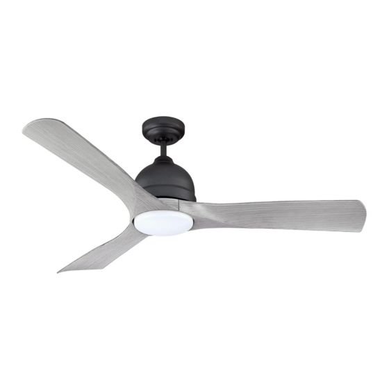
- Page 1 CEILING FAN 54” Ceiling Fan Owner’s Manual BBCF590...
-
Page 2: Table Of Contents
Table of Contents Section Page Section Page Safety Instructions ........2 8. -
Page 3: Unpacking Instructions
This product is designed to use only those parts Fan Blade Assemblies supplied with this product and/or any accessories designated specifically for use with this product LED Light Kit Assembly By Parrot Uncle. Acrylic Shade No-Light Plate Remote Control, SR401 Receiver Open carton containing fan. -
Page 4: Electrical Requirements
1. Unpacking Instructions (Continued) This Manual Is Designed to Make it as Easy as Possible for You to Assemble, Install, Operate and Maintain Your Ceiling Fan THIS FAN IS SUITABLE FOR WET LOCATIONS SUCH AS PORCHES, PATIOS, AND DECKS. Tools Needed for Assembly WARNING One Phillips Head Screwdriver One Stepladder... -
Page 5: Ceiling Fan Assembly
3. Ceiling Fan Assembly PLASTIC BAG MOTOR HUB Remove Fan Motor Assembly from styrofoam. Remove cardboard Shipping Spacer and plastic bag. CARDBOARD SHIPPING SPACER Place Fan Motor Assembly on styrofoam with the Motor Hub positioned up (Figure 1). FAN MOTOR ASSEMBLY Figure 1 1/4-20 x 9/16"... - Page 6 3. Ceiling Fan Assembly (Continued) Carefully turn the partially assembled Ceiling Fan PARTIALLY ASSEMBLED CEILING FAN right side up and position the Fan on the styrofoam in preparation for final assembly (Figure 4). STYROFOAM Figure 4 Remove the Hanger Ball by loosening the Phillips Head GREEN GROUND WIRE Set Screw in the Hanger Ball until the Ball falls freely down the 4.5”...
- Page 7 3. Ceiling Fan Assembly (Continued) Loosen the two Set Screws in the Motor Coupler for installation of the Downrod (Figure 7). Seat the downrod in the Motor Coupler (Figure 7). 4.5" Rotate and align the Downrod Holes with all the Holes DOWNROD in the Motor Coupler (Figure 7).
- Page 8 3. Ceiling Fan Assembly (Continued) 3.10 Place the Ceiling Cover over the Downrod (Figure 10). DOWNROD CEILING Be sure that the Ceiling Cover and the Coupler Cover COVER are both oriented correctly (Figure 10). Figure 10 3.11 Route the three 80” Motor Wires through the Hanger HANGER BALL Ball (Figure 11).
-
Page 9: How To Hang Your Ceiling Fan
4. How to Hang Your Ceiling Fan CEILING CAUTION To reduce the risk of injury, install the fan so that the blades are at least 7 ft. (2.1m) above the floor (Figure 13). LEAST FLOOR Figure 13 WARNING The outlet box and joist must be securely mounted and capable of supporting at least 50 lbs. - Page 10 4. How to Hang Your Ceiling Fan (Continued) NOTE: CEILING COVER, SUPPL Y WIRES AND FAN WIRES Carefully lift the partially assembled Ceiling Fan and OMITTED FOR CLARITY. seat the Hanger Ball/Downrod Assembly on the Hanger Bracket that was just attached to the Outlet Box (Figure 15).
-
Page 11: Light Kit Assembly
5. Light Kit Assembly NOTE: If installing Ceiling Fan without the Light Kit Assembly, Skip to Section 6. Optional Installation of No-Light Plate Assembly, Step 6.4. Engage the Fan Motor 2-Pin Wire Connector into the 2-Pin Wire Connector of the Light Kit Assembly (Figure 16). - Page 12 5. Light Kit Assembly (Continued) ROTATE Rotate the Light Kit Assembly clockwise to engage the ENGAGE AND TIGHTEN CLOCKWISE THE TWO 6-32 x 3/8" two 6-32 x 3/8” Truss Head Screws with Lockwashers in TRUSS HEAD SCREWS the key hole slots. WITH LOCKWASHERS Reinstall the previously removed 6-32 x 3/8”...
-
Page 13: Optional Installation Of No-Light Plate Assembly
6. Optional Installation of No-Light Plate Assembly NOTE: To use the No-Light Plate Assembly, the Light Kit Assembly MUST NOT Be Installed, or Light Kit Assembly MUST Be Removed. WARNING Turning off wall switch is not sufficient. To avoid possible electrical shock, be sure electricity is turned LIGHT KIT off at the main fuse box before wiring. - Page 14 6. Optional Installation of No-Light Plate Assembly (Continued) Place the No-Light Plate into the opening of the Light Kit Adapter, aligning the three Flat Areas on the top edge of the No-Light Plate with the three Raised Dimples on the INTERFERENCE ROTATE Light Kit Adapter and turn the Plate clockwise until it...
-
Page 15: How To Wire Your Ceiling Fan
7. How to Wire Your Ceiling Fan If you feel that you do not have enough electrical wiring knowledge or experience, have your fan installed by a licensed electrician. GROUND WIRE WARNING To avoid possible electrical shock, be sure electricity GREEN GROUND is turned off at the main fuse box before wiring. - Page 16 7. How to Wire Your Ceiling Fan (Continued) Securely connect the Receiver Black Wire (AC in L) to the Supply Black Wire (hot) using the Wire Connector (supplied in parts bag) (Figure 26). SUPPLY BLACK WIRE (Hot) RECEIVER BLACK WIRE (AC in L) Figure 26 S e c u r e l y c o n n e c t t h e R e c e i v e r W h i t e W i r e...
- Page 17 7. How to Wire Your Ceiling Fan (Continued) Securely connect the Receiver Blue Wire (TO LIGHT) to the Fan Motor Blue Wire using the Wire Connector (supplied in parts bag) (Figure 29). RECEIVER BLUE WIRE (TO LIGHT) FAN MOTOR BLUE WIRE Figure 29 While inserting the Receiver fully into the Hanger Bracket, turn Wires upward and carefully push Wires...
-
Page 18: Final Assembly
7. How to Wire Your Ceiling Fan (Continued) Wiring Schematic for reference (Figure 32). STANDARD ON-OFF WALL SWITCH OR OPTIONAL SW405 WALL CONTROL BLACK BLACK RECEIVER BLACK (HOT) ..120- VOLT SUPPLY WHITE WHITE WHITE ANTENNA GROUND BLACK or RED BLUE TWO-CONDUCTOR WHITE... -
Page 19: Reverse Switch Operation
9. Reverse Switch Operation Restore Electrical Power to the Outlet Box by turning the Electricity on at the Main Fuse Box. During Summer Months, run the Fan Counter- Clockwise, as you look up at it, to direct airflow REVERSING downward. REVERSE SWITCH SWITCH... -
Page 20: Remote Control Operation
10. Remote Control Procedures (Continued) 10.3: Setting Operating Frequency of Remote Control REMOTE CONTROL LEVERS Remove the Battery Cover by pressing firmly below the arrow and sliding the Cover off the Control (Figure 36). Your Remote Control has Code Switches which must be set in one of 32 possible code combinations. - Page 21 11.2 POWER INDICATOR The Remote Control is designed to separately control LIGHT your Ceiling Fan Speed and Light Intensity (Figure 38). There are Four Push Buttons ( . , .. , ... , ..) to set the Fan Speed. 11.3 HIGH TO LOW BUTTONS...
-
Page 22: Light Kit Led Array Assembly Replacement
12. Light Kit LED Array Assembly Replacement WARNING WARNING To avoid possible electrical shock, be sure electricity Turning off wall switch is not sufficient. To avoid possible electrical shock, be sure electricity is turned is turned off at the main fuse box before wiring. off at the main fuse box before wiring. -
Page 23: Light Kit Led Driver Replacement
12. Light Kit LED Array Assembly Replacement (Continued) 12.4 Disengage the Fan Motor Assembly 2-Pin Wire Connector from the 2-Pin Wire Connector of the Light Kit Assembly (Figure 43). 12.5 Install new Light Kit Assembly by following the assembly FAN MOTOR instructions in Section 5, Steps 5.1 through 5.4. - Page 24 13. Light Kit LED Driver Replacement (Continued) 13.2 Remove the two Knurled Knobs and Lockwashers from the Threaded Studs. Retain the hardware for future reinstallation (Figure 44). CEILING COVER Slide the Ceiling Cover Downward to rest on top the Motor Housing. THREADED STUDS (2) LOCKWASHERS (2)
- Page 25 13. Light Kit LED Driver Replacement (Continued) 13.6 Slide the Ceiling Cover and the Coupler Cover up and CEILING off the Downrod to access the top of the Motor Housing COVER (Figure 47). DOWNROD COUPLER COUPLING COVER COVER FAN MOTOR HOUSING Figure 47 13.7...
- Page 26 13. Light Kit LED Driver Replacement (Continued) 13.10 MOTOR AC POWER MOTOR DC POWER CONNECTOR Squeeze and unclip the Motor AC Power Connector CONNECTOR LIGHT KIT from the Light Kit LED Driver Connector (Figure 50). LED DRIVER Squeeze and unclip the Motor DC Power Connector from the Light Kit LED Driver Connector (Figure 50).
- Page 27 13. Light Kit LED Driver Replacement (Continued) 13.13 MOTOR AC POWER MOTOR DC POWER CONNECTOR CONNECTOR Reconnect the Motor AC Power Connector to the Light LIGHT KIT LED DRIVER Kit LED Driver Connector (Figure 53). Reconnect the Motor DC Power Connector to the Light Kit LED Driver Connector (Figure 53).
- Page 28 13. Light Kit LED Driver Replacement (Continued) 13.16 Final assembly of the Downrod, Coupler Cover, Ceiling Cover, and Hanger Ball will be completed by following HAIRPIN CLIP the Ceiling Fan Assembly, Sections 3, Steps 3.8 CLEVIS through 3.11. Figure 56 shows the beginning process. 13.17 MOTOR MOTOR...
-
Page 29: Maintenance
14. Maintenance IMPORTANT CARE INSTRUCTIONS WARNING for your Ceiling Fan Do not use water when cleaning your ceiling fan. Periodic cleaning of your new Ceiling Fan is the only It could damage the motor or the blades and create the maintenance that is needed. - Page 30 16. Energy Efficient Use of Ceiling Fans Ceiling Fan performance and energy savings rely Using the Ceiling Fan Year Round. In the summer, heavily on the proper installation and use of the Ceiling use the Ceiling Fan in the counter-clockwise direction. Fan.
Need help?
Do you have a question about the BBCF590 and is the answer not in the manual?
Questions and answers