
Subscribe to Our Youtube Channel
Related Manuals for Parrot Uncle BBCF344


Summary of Contents for Parrot Uncle BBCF344
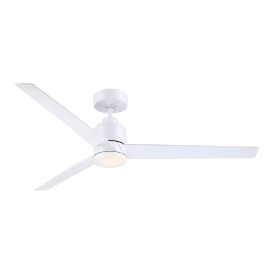
- Page 1 CEILING FAN Ceiling Fan Owner’s Manual 44”BBC F344 / 54”BBCF354 44”BBCF345 / 54”BBCF355...
-
Page 2: Table Of Contents
Table of Contents Section Page Section Page Safety Instructions ........2 6. -
Page 3: Unpacking Instructions
This product is designed to use only those parts Hanger Ball / 4.5” Downrod supplied with this product and/or any accessories designated specifically for use with this product Ceiling Cover by Parrot Uncle. Motor Coupler Cover Light Kit Adapter Fan Blade Support Plates LED Light Fixture Assembly Open carton containing fan. -
Page 4: Electrical Requirements
1. Unpacking Instructions (Continued) THESE FAN MODELS ARE SUITABLE FOR WET LOCATIONS SUCH AS PORCHES, PATIOS, AND DECKS. This Manual Is Designed to Make it as Easy as Possible for You to Assemble, Install, Operate and Maintain Your Ceiling Fan Remove the Fan Motor Assembly from the protective Installed Wire Length Wire Size A.W.G. -
Page 5: Ceiling Fan Assembly
3. Ceiling Fan Assembly Place a Fan Blade onto the Fan Housing Assembly aligning the Three Screw Holes of the Blade with the 1/4-20 x 17 mm PAN HEAD Three Screw Holes of the Fan Housing Assembly SCREWS WITH LOCKWASHERS (Figure 1). - Page 6 3. Ceiling Fan Assembly (Continued) REINSTALL ONE #6-32 x 3/8" PAN Place the 2-pin Motor Assembly Connector through the HEAD SCREW WITH LOCKWASHER Large Center Hole of the Light Kit Adapter (Figure 3). NOTE: Position the 2-pin Motor Assembly TURN ADAPTER CLOCKWISE Connector through the Light Kit Adapter Center LIGHT KIT ADAPTER Hole, making sure that the Light Kit Adapter does...
- Page 7 3. Ceiling Fan Assembly (Continued) DOWNROD Loosen the two Phillips Head Set Screws in the Motor Coupler for installation of the Downrod (Figure 6). Seat the Downrod in the Motor Coupler (Figure 6). LOOSEN SET Rotate and align the Downrod Holes with the two Holes SCREWS (2) in the Motor Coupler (Figure 6).
- Page 8 3. Ceiling Fan Assembly (Continued) DOWNROD Make sure the Rubber Grommet is properly installed in the Motor Coupler Cover. RUBBER Slide the Motor Coupler Cover on the Downrod until it GROMMET MOTOR rests on the Motor Housing (Figure 9). MOTOR HOUSING COUPLER COVER...
- Page 9 3. Ceiling Fan Assembly (Continued) 3.12 GREY WIRE The Fan comes with Blue, White, Grey, Red, and BLUE WIRE Yellow Wires that are 80-inches long. RED WIRE Before installing the Fan, measure up approximately 6 TO 9 6 to 9-inches above top of Hanger Ball / Downrod INCHES WHITE WIRE Assembly (Figure 12).
-
Page 10: How To Hang Your Ceiling Fan
4. How to Hang Your Ceiling Fan CAUTION CEILING To reduce the risk of injury, install the fan so that the blades are at least 7 ft. (2.1m) above the floor (Figure 13). WARNING LEAST To avoid possible electrical shock, be sure electricity is turned off at the main fuse box or circuit breaker panel before wiring. - Page 11 4. How to Hang Your Ceiling Fan (Continued) WARNING The outlet box and joist must be securely mounted and capable of supporting at least 50 lbs. Use only a U.L. outlet box listed as “Acceptable for Fan Support of OUTLET 22.7 kg.
-
Page 12: How To Wire Your Ceiling Fan
To reduce the risk of electrical shock, disconnect the designated specifically for use with this product electrical supply circuit before installing the fan or by Parrot Uncle. receiver. WARNING Turning off wall switch is not sufficient. To avoid... - Page 13 5. How to Wire Your Ceiling Fan (Continued) RECEIVER Securely connect the Supply White (neutral) Wire to WHITE WIRE the Receiver White (AC IN N) Wire using a 12 ga. Wire Connector (supplied in parts bag) (Figure 18). SUPPLY WHITE WIRE Figure 18 Securely connect the Supply Black (hot) Wire to the Receiver Black (AC IN L) Wire using a 12 ga.
- Page 14 5. How to Wire Your Ceiling Fan (Continued) Securely connect the Fan White (neutral) Wire to the Receiver White (FOR LIGHT) Wire using a 18 ga. Wire Connector (supplied with receiver) (Figure 20). FAN WHITE WIRE RECEIVER WHITE WIRE Figure 20 Securely connect the Fan Blue Wire to the Receiver Blue (FOR LIGHT) Wire using a 18 ga.
- Page 15 5. How to Wire Your Ceiling Fan (Continued) Securely connect the Fan Red Wire to the Receiver Red (TO MOTOR) Wire using a 18 ga. Wire Connector (supplied with receiver) (Figure 23). FAN RED WIRE RECEIVER RED WIRE Figure 23 Securely connect the Fan Yellow Wire to the Receiver Yellow (TO MOTOR) Wire using a 18 ga.
- Page 16 5. How to Wire Your Ceiling Fan (Continued) 5.10 After Connections have been made, turn Wires and Connectors upward and carefully push them into the Outlet Box (Figure 25). Position the Antenna Wire on top of the Receiver. Slide the Receiver completely onto the Hanger Ball, nestled OUTLET BOX in the Hanger Bracket (Figure 25).
-
Page 17: Led Light Fixture Installation
6. LED Light Fixture Installation Engage the Fan Motor 2-Pin Wire Connector into the LED Light Fixture Assembly 2-pin Wire Connector (Figure 27) . The connection is complete when you hear a soft click. FAN MOTOR 2-PIN WIRE CONNECTOR LED LIGHT FIXTURE ASSEMBLY 2-PIN WIRE CONNECTOR... - Page 18 6. LED Light Fixture Installation Place the Glass Shade into the opening of the Light Kit Adapter, aligning the Three Flat Areas on the top edge of the Shade with the Three Raised Dimples on the Light Kit Adapter and turn the Glass Shade Clockwise until it stops (Figure 29) .
-
Page 19: Final Assembly
7. Final Assembly Screw the Two Threaded Studs (supplied) into the Tapped Holes in the Hanger Bracket (Figure 30). NOTE: Be sure the wires stay on the outside of the threaded rods when installing the ceiling cover. HANGER BRACKET THREADED STUDS (2) Figure 30 Lift the Ceiling Cover up to the Threaded Studs and turn until studs protrude through the holes in the Ceiling... -
Page 20: Remote Control Procedures
8. Remote Control Procedures 8.1: Preset Memory Feature Your Receiver is equipped with a preset memory When the Switch is turned back ON the Light and Fan feature. If the AC supply to the Receiver is powered will resume operation as they were prior to the Switch through a wall switch, when the switch is turned OFF, being turned OFF. - Page 21 WARNING Fan installation must be completed, including the installation of the fan blades, before testing the remote control. FAN POWER BUTTON Remote Control Pairing: Your Brands Ceiling Fan/Light Remote Control consists of Hand-Held Transmitter and a Receiver which is mounted in the Hanger Bracket under the Fan Ceiling Cover.
- Page 22 Ceiling Fan Air Flow & Speed Control: If Airflow is desired in the opposite direction, press the REVERSE Button ( ) on the Remote Control (Figure 36). The Fan must be operating at any Speed REVERSE for the REVERSE Button to function. The Blades will BUTTON turn in the opposite direction and reverse the airflow.
- Page 23 AUTO TIMER Button ( ) (Figure 38): While the Ceiling Fan is moving, press the AUTO TIMER Button ( ) Once - Runs the Ceiling Fan for 2 Hours. The 2H Indicator Light Will Illuminate. While the Ceiling Fan is moving, press the AUTO TIMER Button ( ) Twice - Runs the Ceiling Fan for 4 Hours.
-
Page 24: Maintenance
9. Maintenance IMPORTANT CARE INSTRUCTIONS WARNING for your Ceiling Fan Do not use water when cleaning your ceiling fan. Periodic cleaning of your new ceiling fan is the only It could damage the motor or the blades and create the maintenance that is needed. -
Page 25: Troubleshooting
WARNING Make sure main power is turned OFF. WARNING Make sure main power is turned OFF. INSTRUCTION TO THE USER (if device contains a digital device) This equipment has been tested and found to comply with the limits for a class B digital device, pursuant to part 15 of the FCC Rules.
Need help?
Do you have a question about the BBCF344 and is the answer not in the manual?
Questions and answers