Table of Contents
Advertisement
Quick Links
Advertisement
Table of Contents

Related Manuals for Parrot Uncle BBCF985


Summary of Contents for Parrot Uncle BBCF985
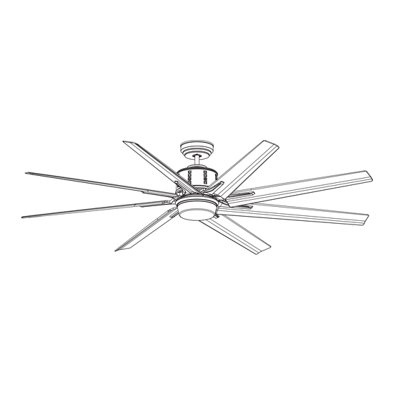
- Page 1 CEILING FAN 72” Ceiling Fan Owner’s Manual BBCF985...
-
Page 2: Table Of Contents
Table of Contents Section Page Section Page Safety Instructions ....... . 2 10. -
Page 3: Unpacking Instructions
1. Unpacking Instructions PACKAGE CONTENTS WARNING Part Description Qty. Do not install or use fan if any part is damaged or missing. Fan Motor Assembly Hanger Bracket Hanger Ball / 6” Downrod Assembly Ceiling Cover WARNING Coupler Cover This product is designed to use only those parts Lower Housing supplied with this product and/or any accessories LED Light Fixture Assembly... -
Page 4: Electrical Requirements
1. Unpacking Instructions (Continued) This Manual Is Designed to Make it as Easy as Possible for You to Assemble, Install, Operate and Maintain Your Ceiling Fan THIS FAN IS SUITABLE FOR DAMP LOCATIONS SUCH AS COVERED PORCHES, COVERED PATIOS, AND COVERED DECKS. ANYWHERE THERE IS A ROOF OVERHEAD. -
Page 5: Ceiling Fan Assembly
3. Ceiling Fan Assembly WARNING Disconnect electrical power to the Branch Circuit at the Turning off wall switch is not sufficient. To avoid Circuit Breaker or Fuse Box before attempting to install possible electrical shock, be sure electricity is turned the Ceiling Fan Hanger Bracket on the Outlet Box. - Page 6 3. Ceiling Fan Assembly (Continued) Loosen the two Set Screws in the Motor Coupler. Place the 6” Downrod into the Motor Coupler, aligning HAIRPIN the Clevis Pin Holes in the Downrod with the Holes in 6" DOWNROD CLIP the Motor Coupler (Figure 3). CLEVIS The Clevis Pin must go through the Holes in the Motor Coupler and the Holes in the Downrod.
- Page 7 3. Ceiling Fan Assembly (Continued) 6" DOWNROD Route the 80” Black and White Motor Wires through the Ceiling Cover (Figure 6). Place the Ceiling Cover over the Downrod. Be sure CEILING both the Ceiling Cover and the Coupler Cover are COVER oriented correctly (Figure 6).
-
Page 8: How To Hang Your Ceiling Fan
4. How to Hang Your Ceiling Fan CAUTION CEILING To reduce the risk of injury, install the fan so that the WARNING Turning off wall switch is not sufficient. To avoid possible electrical shock, be sure electricity is turned AT LEAST off at the main fuse box before wiring. - Page 9 4. How to Hang Your Ceiling Fan (Continued) Remove the Socket Head Cap Screw with the Hex Wrench (supplied in the parts bag) from the Retaining OUTLET Strap to the Hanger Bracket (Figure 11); retain the Socket Head Cap Screw for future use. RETAINING STRAP Swing open the Retaining Strap as shown in Figure 11.
-
Page 10: How To Wire Your Ceiling Fan
4. How to Hang Your Ceiling Fan (Continued) Rotate the Retaining Strap closed (Figure 13) on the Hanger Bracket. Reinstall the Socket Head Cap Screw (previously removed). Securely tighten the Socket Head Cap RETAINING STRAP Screw (Figure 13). HANGER BRACKET SOCKET CAP SCREW HEX WRENCH Figure 13... - Page 11 5. How to Wire Your Ceiling Fan (Continued) Securely connect the Fan Motor White Wire to the Supply White (neutral) Wire using Wire Connector SUPPLY WHITE supplied (Figure 15). (NEUTRAL) LISTED WIRE CONNECTOR FAN MOTOR WHITE WIRE Figure 15 Securely connect the Fan Motor Black Wire to the Supply Black (hot) Wire using Wire Connector supplied FAN MOTOR (Figure 16).
-
Page 12: Final Assembly
6. Final Assembly Screw the two Threaded Studs (supplied) into the tapped holes in the Hanger Bracket (Figure 18). HANGER BRACKET THREADED STUD (2) Figure 18 Lift the Ceiling Cover up to the Threaded Studs and turn until Studs protrude through the holes in the Ceiling Cover (Figure 19). - Page 13 6. Final Assembly (Continued) Remove the Shipping Spacers and the Spacer Attachment Screws from the Fan Motor before installation of Blade Assemblies (Figure 20). Discard the Spacers and Spacer Screws. MOTOR ASSEMBLY SHIPPING SPACER (8) SHIPPING SPACER SCREW (8) Figure 20 #8-32 x 3/8"...
- Page 14 6. Final Assembly (Continued) Remove one of the three #6-32 x 3/8” Truss Head Screws with Lockwashers from the Fan Motor Assembly (Figure 23). Retain the Screw for future installation. Loosen the other two Screws several turns. WARNING between the fan motor assembly and the lower housing.
- Page 15 6. Final Assembly (Continued) If using the No-Light Cover, skip this Section and go to Section 7. Remove one of the three #6-32 x 3/8” Truss Head Screw with Lockwasher from the Lower Housing (Figure 25). Retain the Screw for future installation. Loosen the other two Screws several turns.
- Page 16 6. Final Assembly (Continued) 6.10 ROTATE LED LIGHT FIXTURE ASSEMBLY CLOCKWISE TO ENGAGE THE TWO LOOSENED SCREWS Install the LED Light Fixture Assembly onto the Lower Housing by aligning and engaging the keyhole slots of the LED Light Fixture Assembly with the loosened screw heads on the Lower Housing (Figure 27).
-
Page 17: Optional Installation Of No-Light Cover
7. Optional Installation of No-Light Cover WARNING Turning off wall switch is not sufficient. To avoid possible electrical shock, be sure electricity is turned off at the main fuse box before wiring. All wiring must be in accordance with National and Local codes and the ceiling fan must be properly grounded as a precaution against possible electrical shock. - Page 18 7. Optional Installation of No-Light Cover (Continued) Disengage and retain the Fan Motor 2-Pin Wire Connector from the 2-pin Wire Connector of the LED Light Fixture Assembly (Figure 31). NOTE: Store the LED Light Fixture Assembly in a safe place for future use, if needed. DISENGAGE FAN MOTOR 2-PIN WIRE CONNECTOR...
-
Page 19: Wall Control Procedures
8. Wall Control Procedures Code Switches in the Transmitter may be set in 32 different positions. If your Fan and Light turn ON and Your Ceiling Fan/Light Control consists of Wall OFF without using your Control, you may be getting Mounted Transmitter and a Receiver located inside the interference from other remote units such as garage Motor Assembly. -
Page 20: Wall Control Installation
9. Wall Control Installation NOTE: Make all wiring connections using WARNING Wire Connectors (supplied). Make sure that all connections are tight, including ground, and that no Turning off wall switch is not sufficient. To avoid bare wire is visible at the wire connectors, except possible electrical shock, be sure electricity is turned for the ground wire. - Page 21 9. Wall Control Installation (Continued) Skip to Section 9.4 if Using a 3-way Switch Installation. SCREWS (2) SCREWS (2) FAN/LIGHT WALL CONTROL SINGLE-POLE INSTALLATION (One Fan Controlled by One Wall Control) (See Figure 35)..WARNING Turning off wall switch is not sufficient. To avoid possible electrical shock, be sure electricity is turned NEUTRAL SWITCH COVER...
- Page 22 9. Wall Control Installation (Continued) 3-WAY INSTALLATION FAN/LIGHT SECOND FAN/LIGHT WALL WALL CONTROL (One Fan Controlled by Two Different Wall Controls) CONTROL (Purchased Separately) (See Figures 36 and 37). GROUND GROUND WARNING Turning off wall switch is not sufficient. To avoid possible electrical shock, be sure electricity is turned off at the main fuse or circuit breaker box before TRAVELER...
- Page 23 9. Wall Control Installation (Continued) STANDARD WIRING FOR EXISTING Disconnect Electrical Power to the Branch Circuit at the 3-WAY CONTROLS Circuit Breaker or Fuse Box before attempting to install EXISTING the Ceiling Fan Wall Control into the Wall Box. WALL CONTROL Before installing the Second Wall Control, place the Wall Control in “OFF”...
-
Page 24: Programming Fan Control
10. Programming the Receiver Operating Frequency & High Speed Conditioning of Fan Control -- Important - Read This Section Carefully and Follow the High Speed Conditioning Instructions Closely -- 10.2 PROGRAMMING THE RECEIVER OPERATING FREQUENCY & HIGH SPEED The Fan will run for approximately 2 minutes in the CONDITIONING OF FAN CONTROL and run an additional 2 minutes. -
Page 25: Using Your Ceiling Fan
11. Using Your Ceiling Fan WARNING Fan installation must be completed, including the installation of the fan blades, before testing the remote control. POWER Your Wall Control has full control of your Fan and Light INDICATOR (Figure 38). LIGHT LIGHT AIRFLOW INTENSITY 11.1... -
Page 26: Maintenance
12. Maintenance IMPORTANT CARE INSTRUCTIONS WARNING for your Ceiling Fan Do not use water when cleaning your ceiling fan. Periodic cleaning of your new ceiling fan is the only It could damage the motor or the blades and create the maintenance that is needed. -
Page 27: Troubleshooting
14. Troubleshooting TROUBLE PROBABLE CAUSE SUGGESTED REMEDY 1. Fan will not start. 1. Fuse or circuit breaker blown. 1. Check main and branch circuit fuses or circuit breakers. WARNING Make sure main power is turned OFF. 2. Loose power line connections to the fan, 2.
Need help?
Do you have a question about the BBCF985 and is the answer not in the manual?
Questions and answers