Table of Contents
Advertisement
Quick Links
Advertisement
Table of Contents

Subscribe to Our Youtube Channel
Related Manuals for Parrot Uncle BBCF575


Summary of Contents for Parrot Uncle BBCF575
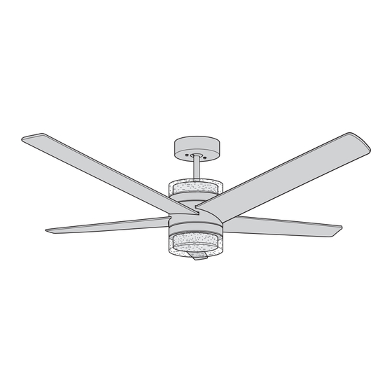
- Page 1 CEILING FAN 52” Ceiling Fan Owner’s Manual BBCF575...
-
Page 2: Table Of Contents
Table of Contents Section Page Section Page 7. Wall Control Installation ......21-25 Safety Instructions ........2 1. -
Page 3: Unpacking Instructions
1. Unpacking Instructions WARNING Do not install or use fan if any part is damaged or missing. PACKAGE CONTENTS Part Description Quantity WARNING Fan Motor Assembly Hanger Bracket This product is designed to use only those parts supplied with this product and/or any accessories Hanger Ball / 7”... -
Page 4: Electrical Requirements
1. Unpacking Instructions (Continued) This Manual Is Designed to Make it as Easy as Possible for You to Assemble, Install, Operate and Maintain Your Ceiling Fan Remove the Fan Motor Assembly from the protective WARNING plastic bag. Place the Fan Motor Assembly, Bottom of the Motor facing up, on a steady work table. -
Page 5: Ceiling Fan Assembly
3. Ceiling Fan Assembly NOTE: Take care not to scratch the Fan Housing INSTALL AND TIGHTEN #8-32 x 11mm WASHER HEAD Assembly when installing the Blades. BLADE SCREWS (3 per blade) Slide the Blade into the Fan Housing Assembly Blade Slot (Figure 1). - Page 6 3. Ceiling Fan Assembly (Continued) LOWER HOUSING Place the 2-pin Motor Assembly Wires and Connector ASSEMBLY REINSTALL AND TIGHTEN ONE through the Lower Housing Assembly Center Hole. #6-32 x 3/8" TRUSS HEAD SCREW WITH LOCKWASHER Position the Lower Housing Assembly Key Hole Slots onto the Two Loosened Screw Heads.
- Page 7 3. Ceiling Fan Assembly (Continued) REMOVE AND RETAIN ONE Remove and Retain One of the Three #6-32 x 1/4” #6-32 x 1/4" TRUSS HEAD SCREW WITH LOCKWASHER Truss Head Screw with Lockwasher from the Lower Housing Assembly (Figure 5). LOWER Loosen the remaining Two #6-32 x 1/4”...
- Page 8 3. Ceiling Fan Assembly (Continued) Carefully turn the partially assembled Ceiling Fan right GREEN GROUND WIRE side up for preparation of remaining assembly. Remove the Hanger Ball by loosening the Phillips Head Set Screw in the Hanger Ball until the Ball falls freely down the 7”...
- Page 9 3. Ceiling Fan Assembly (Continued) IMPORTANT: Remove the Clear Protective Film DOWNROD from around the LED Upper Light. Loosen the Two Phillips Head Set Screws in the Motor Coupler for installation of the Downrod (Figure 9). Seat the Downrod in the Motor Coupler (Figure 9). Rotate and align the Downrod holes with the Two Holes in the Motor Coupler (Figure 9).
- Page 10 3. Ceiling Fan Assembly (Continued) 3.11 Retighten the Two Phillips Head Set Screws evenly to DOWNROD RETIGHTEN secure the Downrod to the Motor Coupler in a vertical PHILLIPS HEAD position (Figure 11). SET SCREWS (2) WARNING MOTOR COUPLER It is critical that the set screws in the motor coupler are securely tightened.
- Page 11 3. Ceiling Fan Assembly (Continued) 3.13 Locate the Upper Outer Shade, which is larger in size DOWNROD and has a hole in the center. UPPER OUTER SHADE Route the Four Wires through the Center Hole of the Upper Outer Shade and slide it down the Downrod. Position the Upper Outer Shade’s Three Flat Areas into the Fan Motor Housing’s Three Raised Dimples.
- Page 12 3. Ceiling Fan Assembly (Continued) 3.15 HANGER BALL Route the Four Wires through the Hanger Ball (Figure 15). Reinstall the Hanger Ball on the Downrod as follows: DOWNROD Position the Pin through the Two Holes in the Downrod PHILLIPS SET SCREW and align the Hanger Ball so the Pin is captured in the Groove in the top of the Hanger Ball (Figure 15).
-
Page 13: How To Hang Your Ceiling Fan
4. How to Hang Your Ceiling Fan CAUTION CEILING To reduce the risk of injury, install the fan so that the blades are at least 7 ft. (2.1m) above the floor (Figure 17). WARNING To avoid possible electrical shock, be sure electricity is turned off at the main fuse box before wiring. - Page 14 4. How to Hang Your Ceiling Fan (Continued) WARNING The outlet box and joist must be securely mounted and capable of supporting at least 50 lbs. Use only a U.L. outlet box listed as “Acceptable for Fan Support of OUTLET BOX 22.7 kg.
-
Page 15: How To Wire Your Ceiling Fan
5. How to Wire Your Ceiling Fan If you feel that you do not have enough electrical wiring knowledge or experience, have your fan installed by a licensed electrician. DOWNROD RECEIVER WARNING To avoid possible electrical shock, be sure electricity is turned off at the main fuse box before wiring. - Page 16 5. How to Wire Your Ceiling Fan (Continued) Securely connect the Supply White (neutral) Wire to the Receiver White (AC IN N) Wire and the Fan White Wire using a 12 ga. Wire Connector (supplied in parts bag) SUPPLY WHITE WIRE (Figure 22).
- Page 17 5. How to Wire Your Ceiling Fan (Continued) Securely connect the Fan Blue Wire to the Receiver Blue (FOR BOTTOM LIGHT) Wire using a 12 ga. Wire Connector (supplied in parts bag) (Figure 24). FAN BLUE WIRE RECEIVER BLUE WIRE Figure 24 Securely connect the Fan Black Wire to the Receiver Black (TO MOTOR L) Wire using a 12 ga.
- Page 18 5. How to Wire Your Ceiling Fan (Continued) Securely connect the Fan Yellow Wire to the Receiver Yellow (FOR UPPER LIGHT) Wire using a 12 ga. Wire Connector (supplied in parts bag) (Figure 26). FAN YELLOW WIRE RECEIVER YELLOW WIRE Figure 26 Complete wiring diagram of Receiver, Supply &...
-
Page 19: Final Assembly
6. Final Assembly Screw the Two Threaded Studs (supplied) into the Tapped Holes in the Hanger Bracket (Figure 28). HANGER BRACKET THREADED STUDS (2) Figure 28 After Connections have been made, turn Wires and Connectors upward and carefully push them into the Outlet Box (Figure 29). - Page 20 6. Final Assembly (Continued) Place the Lower Inner Shade (no center hole) into the opening of the LED Light Fixture Assembly. Align the Three Flat Areas on the top edge of the Lower Inner Shade with the Three Raised Dimples on the LED Light Fixture Assembly and turn the Shade Clockwise until it stops (Figure 31).
-
Page 21: Wall Control Installation
7. Wall Control Installation Code Switches in the Transmitter may be set in Your Ceiling Fan/Light Control consists of Wall 32 different positions. If your Fan and Light turn ON Mounted Transmitter and a Receiver located inside and OFF without using your Control, you may be the Ceiling Cover. - Page 22 7. Wall Control Installation (Continued) NOTE: Make all wiring connections using WARNING Wire Connectors (supplied). Make sure that all connections are tight, including ground, and that no Turning off wall switch is not sufficient. To avoid bare wire is visible at the wire connectors, except possible electrical shock, be sure electricity is turned for the ground wire.
- Page 23 7. Wall Control Installation (Continued) Skip to Section 7.7 if Using a 3-way Switch Installation. SCREWS (2) SCREWS (2) SW605 FAN/LIGHT WALL CONTROL SINGLE-POLE INSTALLATION (One Fan Controlled by One Wall Control) (See Figures 35 and 36)..WARNING Turning off wall switch is not sufficient. To avoid possible electrical shock, be sure electricity is turned NEUTRAL off at the main fuse or circuit breaker box before...
- Page 24 7. Wall Control Installation (Continued) 3-WAY INSTALLATION SECOND SW605 (One Fan Controlled by Two Different Wall Controls) FAN/LIGHT (See Figures 37 and 38). SW605 WALL CONTROL FAN/LIGHT (Purchased Separately) WALL CONTROL GROUND GROUND WARNING Turning off wall switch is not sufficient. To avoid possible electrical shock, be sure electricity is turned off at the main fuse or circuit breaker box before TRAVELER...
- Page 25 7. Wall Control Installation (Continued) STANDARD WIRING FOR EXISTING 3-WAY CONTROLS Disconnect Electrical Power to the Branch Circuit at the Circuit Breaker or Fuse Box before attempting to install the Ceiling Fan Wall Control into the Wall Box. EXISTING WALL CONTROL Before installing the Second Wall Control, place the Wall Control in “OFF”...
-
Page 26: Programming The Receiver Operating Frequency
8. Programming the Receiver Operating Frequency PROGRAMMING THE RECEIVER OPERATING FREQUENCY If programming is unsuccessful, retry the Step 8.1 instructions after cycling the Wall Control ON/OFF Switch to restart the 1 minute programming time period. Flip the Wall Control ON/OFF Switch ( ) to the “OFF”... -
Page 27: Using Your Ceiling Fan
9. Using Your Ceiling Fan WARNING Fan installation must be completed, including the installation of the fan blades, before testing the remote control. POWER Your Wall Control has full control of your Fan and Light INDICATOR LIGHT (Figure 39)..LIGHT INTENSITY AIRFLOW... -
Page 28: Maintenance
10. Maintenance IMPORTANT CARE INSTRUCTIONS WARNING for your Ceiling Fan Do not use water when cleaning your ceiling fan. Periodic cleaning of your new ceiling fan is the only It could damage the motor or the blades and create the maintenance that is needed. -
Page 29: Energy Efficient Use Of Ceiling Fans
11. Energy Efficient Use of Ceiling Fans Ceiling fan performance and energy savings rely Using the Ceiling Fan Year Round. In the summer, heavily on the proper installation and use of the ceiling use the ceiling fan in the counter-clockwise direction. fan. -
Page 30: Troubleshooting
TROUBLE PROBABLE CAUSE SUGGESTED REMEDY 1. Fan will not start. 1. Fuse or Circuit Breaker blown. 1. Check Main and Branch Circuit Fuses or Circuit Breakers. WARNING Make sure main power is turned OFF. 2. Loose power line connections to the Fan. 2.
Need help?
Do you have a question about the BBCF575 and is the answer not in the manual?
Questions and answers