Table of Contents
Advertisement
Quick Links
Advertisement
Table of Contents

Subscribe to Our Youtube Channel
Related Manuals for Parrot Uncle BBCF444


Summary of Contents for Parrot Uncle BBCF444
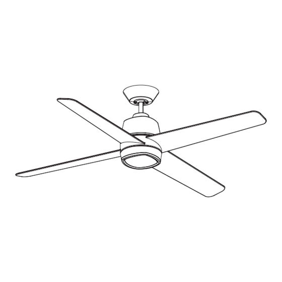
- Page 1 CEILING FAN 54” Ceiling Fan Owner’s Manual BBCF444...
-
Page 2: Table Of Contents
Table of Contents Section Page ection Page Safety Instructions ....... . 2 11. -
Page 3: Unpacking Instructions
This product is designed to use only those parts supplied with this product and/or any accessories Hanger Bracket designated specifically for use with this product Hanger Ball / 6” Downrod Assembly by Parrot Uncle . Receiver with Hardware 4 Speed Wall Control Transmitter with Hardware Fan Blades Open Carton containing the Fan. -
Page 4: Electrical Requirements
1. Unpacking Instructions (Continued) This Manual Is Designed to Make it as Easy as Possible for You to Assemble, Install, Operate and Maintain Your Ceiling Fan Your Ceiling Fan comes supplied with a Receiver and Wall Control. This system allows you to regulate Remove the Fan Motor Assembly from the protective your Ceiling Fan Speed and Light. -
Page 5: Ceiling Fan Assembly
3. Ceiling Fan Assembly #8-32 x 11 mm WASHER Slide a Blade through the Fan Motor Assembly Center HEAD BLADE SCREWS BLADES (4) (3 per blade) Blade Slot. FAN MOTOR ASSEMBLY Mount the Blade to Fan Motor Assembly using Three CENTER BLADE SLOTS (4) #8-32 x 11 mm Washer Head Blade Screws (supplied) (Figure 1). - Page 6 3. Ceiling Fan Assembly (Continued) REINSTALL THREE #6-32 x 3/8" PAN HEAD SCREWS WITH Position the Light Fixture Adapter onto the Fan Motor ALIGN THREE LIGHT FIXTURE LOCKWASHERS ADAPTER SLOTS WITH THE Assembly Hub. THREE MOTOR HUB HOLES NOTE: When positioning, it is critical to align the four inside corners of the Light Fixture Adapter to the four corners of the Fan Motor Assembly’s Upper Housing.
- Page 7 THREE 80" MOTOR WIRES (UNTWISTED) Separate, untwist and unkink the Three 80” Motor Wires. Route the Three 80” Black, Blue, and White Motor Wires through the 6” Downrod (Figure 5). 6" DOWNROD Figure 5 DOWNROD Loosen the Two Phillips Head Set Screws in the Motor MOTOR Coupler for installation of the 6”...
- Page 8 3. Ceiling Fan Assembly (Continued) HAIRPIN Install the Clevis Pin and secure with the Hairpin Clip CLIP (Figure 7). CLEVIS The Clevis Pin must go through the Holes in the Motor CLEVIS PIN Coupler and Downrod. It is critical that the Clevis Pin HAIRPIN in the Motor Coupler is properly installed and securely CLIP...
- Page 9 3. Ceiling Fan Assembly (Continued) 3.10 6" DOWNROD Place the Ceiling Cover over the 6” Downrod (Figure 10). Be sure that the Ceiling Cover and the Coupler Cover are both oriented correctly (Figure 10). CEILING COVER Figure 10 3.11 Route the three Motor Wires through the Hanger Ball (Figure 11).
-
Page 10: How To Hang Your Ceiling Fan
CAUTION CEILING To reduce the risk of injury, install the fan so that the blades are at least 7 ft. (2.1m) above the floor (Figure 13). WARNING Turning off wall switch is not sufficient. To avoid possible electrical shock, be sure electricity is turned off at the main fuse box before wiring. - Page 11 Securely attach the Hanger Bracket to the Outlet Box using the Two Screws supplied with the Outlet Box (Figure 15). OUTLET HANGER TWO SCREWS BRACKET SUPPLIED WITH OUTLET BOX ANTI-ROTATION Figure 15 Carefully lift the Fan and seat the Hanger Ball/ Downrod Assembly on the Hanger Bracket that was just attached to the Outlet Box (Figure 16).
-
Page 12: How To Wire Your Ceiling Fan
All wiring designated specifically for use with this product must be in accordance with National and Local codes by Parrot Uncle. and the ceiling fan must be properly grounded as a precaution against possible electrical shock. - Page 13 5. How to Wire Your Ceiling Fan (Continued) NOTE: Make all wiring connections using the wire connectors supplied in the parts bag and the receiver hardware bag. Make sure that all connections are tight, including ground, and that no bare wire is visible at the wire connectors, except for the supply circuit ground wire.
- Page 14 5. How to Wire Your Ceiling Fan (Continued) Securely connect the Receiver Black Wire (AC IN L) to the Supply Black Wire (HOT) using the 12 ga. Wire Connector (supplied in parts bag) (Figure 20). 12 ga. WIRE CONNECTOR SUPPLY AND RECEIVER BLACK WIRES Figure 20...
- Page 15 5. How to Wire Your Ceiling Fan (Continued) Securely connect the Receiver Black Wire (TO MOTOR L) to the Fan Motor Black Wire using the 18 ga. Wire Connector (supplied with receiver) (Figure 22). SUPPLY AND RECEIVER BLACK WIRES 18 ga. WIRE CONNECTOR Figure 22 Securely connect the Receiver Blue Wire (TO LIGHT) ANTENNA WIRE...
- Page 16 5. How to Wire Your Ceiling Fan (Continued) While inserting the Receiver fully into the Hanger WIRE CONNECTORS Bracket, turn Wires upward and carefully push Wires (Tucked Inside into the Outlet Box, with the White and Green Wires Outlet Box) on one side of the Outlet Box and position the Black and Blue Wires on the other side of the Outlet Box (Figure 24).
-
Page 17: Final Assembly
Screw the 1-1/4” Threaded Studs into the Threaded Holes on the bottom of the Hanger Bracket with your fingers (Figure 26). HANGER BRACKET THREADED STUDS (2) Figure 26 Lift the Ceiling Cover up to the Threaded Studs and turn until Studs protrude through the Ceiling Cover Holes (Figure 27). - Page 18 Engage the Fan Motor 2-Pin Wire Connector into the 2-pin Wire Connector of the LED Light Fixture Assembly (Figure 28). The connection is complete when you hear a soft click. FAN MOTOR ASSEMBLY CONNECTOR LED LIGHT FIXTURE ASSEMBLY CONNECTOR FAN MOTOR CONNECTOR LED LIGHT CONNECTOR...
- Page 19 RED DOTS Position the Inner Lower Housing onto the Light Fixture Adapter, aligning the Four Screw Holes. INNER LOWER HOUSING NOTE: Be sure the Red Dot on the Inner Lower Housing aligns with the Red Dot on the Light Fixture Adapter, as shown. Install and tighten the Four #6-32 x 8 mm Flat Head Screws (supplied) to complete the installation of the Inner Lower Housing (Figure 30).
-
Page 20: Wall Control Procedures
7. Wall Control Procedures Code Switches in the Transmitter may be set in 32 different positions. If your Fan and Light turn ON Your Ceiling Fan/Light Control consists of Wall and OFF without using your Control, you may be Mounted Transmitter and a Receiver located inside getting interference from other remote units such as the Ceiling Cover. -
Page 21: Wall Control Installation
8. Wall Control Installation NOTE: Make all wiring connections using WARNING Wire Connectors (supplied). Make sure that all connections are tight, including ground, and that no Turning off wall switch is not sufficient. To avoid bare wire is visible at the wire connectors, except possible electrical shock, be sure electricity is turned for the ground wire. - Page 22 8. Wall Control Installation (Continued) Skip to Section 8.4 if Using a 3-way Switch SCREWS (2) FAN/LIGHT WALL Installation. WALL CONTROL SINGLE-POLE INSTALLATION (One Fan Controlled by One Wall Control) ..(See Figure 34). WARNING Turning off wall switch is not sufficient. To avoid NEUTRAL possible electrical shock, be sure electricity is turned SWITCH COVER...
- Page 23 8. Wall Control Installation (Continued) 3-WAY INSTALLATION FAN/LIGHT SECOND WALL (One Fan Controlled by Two Different Wall Controls) WALL CONTROL ..(See Figures 35 and 36). CONTROL (PURCHASED SEPARATELY) WARNING LOAD Turning off wall switch is not sufficient. To avoid TRAVELER possible electrical shock, be sure electricity is turned BLACK...
- Page 24 8. Wall Control Installation (Continued) STANDARD WIRING FOR EXISTING 3-WAY CONTROLS Disconnect Electrical Power to the Branch Circuit at the Circuit Breaker or Fuse Box before attempting to install EXISTING the Ceiling Fan Wall Control into the Wall Box. WALL CONTROL Before installing the Second Wall Control, place the Wall Control in “OFF”...
-
Page 25: Programming The Receiver Operating Frequency
9. Programming the Receiver Operating Frequency ..PROGRAMMING THE RECEIVER OPERATING FREQUENCY If programming is unsuccessful, retry the previous instructions after cycling the Wall Control ON/OFF Switch to restart the 1 minute programming time period. Turn the Wall Control ON/OFF Switch ( ) to the “OFF”... -
Page 26: Using Your Ceiling Fan
11. Using Your Ceiling Fan 11.1 Restore Electrical Power to the Outlet Box by turning the Electricity on at the Main Fuse Box. During Summer Months, run the Fan Counter- Clockwise, as you look up at it, to direct airflow downward. -
Page 27: Troubleshooting
13. Troubleshooting WARNING FOR YOUR OWN SAFETY TURN OFF POWER AT FUSE BOX OR CIRCUIT BREAKER BEFORE TROUBLESHOOTING YOUR FAN. TROUBLE PROBABLE CAUSE SUGGESTED REMEDY TROUBLE PROBABLE CAUSE SUGGESTED REMEDY 1. Fan will not start. 1. Fuse or circuit breaker blown. 1. -
Page 28: Energy Efficient Use Of Ceiling Fan
14. Energy Efficient Use of Ceiling Fans Using the Ceiling Fan Year Round. In the summer, Ceiling fan performance and energy savings rely heavily on the proper installation and use of the use the ceiling fan in the counter-clockwise direction. ceiling fan.
Need help?
Do you have a question about the BBCF444 and is the answer not in the manual?
Questions and answers