Table of Contents
Advertisement
Advertisement
Table of Contents

Subscribe to Our Youtube Channel
Related Manuals for L-Acoustics L Series


Summary of Contents for L-Acoustics L Series
- Page 1 owner's manual (EN)
- Page 2 Document reference: L2 owner's manual (EN) version 2.0 Distribution date: October 2, 2023 © 2023 L-Acoustics. All rights reserved. No part of this publication may be reproduced or transmitted in any form or by any means without the express written consent of the publisher.
-
Page 3: Table Of Contents
Contents Safety................................6 Instructions..............................6 Introduction................................ 8 L2/L2D 16-channel active progressive curvature WST enclosures..............8 How to use this manual..........................9 Revision history............................9 System components............................10 System component illustrations........................11 Electro-acoustical description..........................14 Polar pattern............................14 Adjustable ns............................15 Directivity............................... 19 Preset description............................ 22 Connectors............................. 23 Rigging system description..........................24 L2/L2D.............................. - Page 4 Mechanical safety.............................45 Loudspeaker congurations..........................47 Line source............................. 47 Line source with low-frequency element................... 48 Rigging procedures............................51 Securing L2/L2D on L2-CHARIOT/L2D-CHARIOT..................51 Flying..............................57 Securing LA-RAK III on L2-BUMP with LA-RAKMOUNT...............57 Flying an L2/L2D array with L2-BUMP and L2-BAR................60 Flying an L2/L2D array with L2-RIGBAR..................70 Adding a pullback with L2-RIGBAR....................
- Page 5 L2-CHARIOTLID............................. 140 L2D-CHARIOTLID........................... 141 APPENDIX A: Recommendation for speaker cables.................... 142 APPENDIX B: Installing a laser inclinometer.......................143 L2-LASERMOUNT..........................143 L2-BUMP.............................. 144...
-
Page 6: Safety
Respect the Working Load Limit (WLL) of third party equipment. L-Acoustics is not responsible for any rigging equipment and accessories provided by third party manufacturers. Verify that the Working Load Limit (WLL) of the suspension points, chain hoists and all additional hardware rigging accessories is respected. - Page 7 This system is intended for use by trained personnel for professional applications. As part of a continuous evolution of techniques and standards, L-Acoustics reserves the right to change the specications of its products and the content of its documents without prior notice.
-
Page 8: Introduction
xed installations. Born from more than 30 years of constant line source technology evolution and from statistical analysis of sound system deployment on the eld, L Series is a denitive answer to all the challenges rental productions and integrators face.The L Series leverages the WST technology and advanced electronic enhancement to deliver state-of-the-art SPL per meter, SPL per weight, and SPL per surface area, forming an ultra-light, ultra-fast, and ultra- simple system to deploy. -
Page 9: How To Use This Manual
• Connection to LA amplied controllers (p.86) As part of a continuous evolution of techniques and standards, L-Acoustics reserves the right to change the specications of its products and the content of its document without prior notice. Please check www.l-acoustics.com on a regular basis to download the latest document and software updates. -
Page 10: System Components
System components System components Loudspeaker enclosures 16-channel active progressive curvature WST 10° enclosure: 4 × 12" LC + 8 × 10" LF + 8 × 3" HF 16-channel active progressive curvature WST 60° enclosure: 4 × 12" LC + 8 × 10" LF + 8 × 3"... -
Page 11: System Component Illustrations
System components DELTA 1.5T Azimuth angle tuning accessory 1.5T Transportation accessories L2-CHARIOT Chariot for one L2 L2-CHARIOTCOV Protective cover for L2 L2-CHARIOTLID Protective lid for L2-CHARIOT L2D-CHARIOT Chariot for one L2D L2D-CHARIOTCOV Protective cover for L2D L2D-CHARIOTLID Protective lid for L2D-CHARIOT L2-BUMPFLIGHT Modular ightcase for 1 L2-BUMP and rigging elements L2-BUMPFLIGHT extension for one additional L2-BUMP... - Page 12 System components Rigging accessories L2-BUMP L2-BAR L2-RIGBAR LA-RAKMOUNT BPCHAIN K2-JACK DELTA 1.5T 1.5T LASERMOUNT Software applications Soundvision LA Network Manager Transportation L2-CHARIOT L2-CHARIOTCOV L2-CHARIOTLID L2 owner's manual (EN) version 2.0...
- Page 13 System components L2D-CHARIOT L2D-CHARIOTCOV L2D-CHARIOTLID L2-BUMPFLIGHT L2-BUMPFLIGHTADDLAYER L2-ROLL L2 owner's manual (EN) version 2.0...
-
Page 14: Electro-Acoustical Description
Electro-acoustical description Electro-acoustical description Polar pattern L2 and L2D each feature eight low frequency loudspeakers. L2 and L2D each feature four low cardioid (LC) loudspeakers on the sides, allowing a standard array to exhibit a broadband cardioid pattern that minimizes rear SPL at low frequencies. With the appropriate presets, the array can alternatively exhibit a supercardioid pattern that minimizes side SPL at low frequencies. -
Page 15: Adjustable Ns
Electro-acoustical description Adjustable ns Horizontal directivity can be set independently on the four Panex modules of L2 and the top two Panex modules of L2D using the push-push mechanism of the ns in combination with the specic electronic presets. There are four possible settings: 70°... - Page 16 Electro-acoustical description 110° setting (preset [L2 110xx] / [L2D 110xx]) 70° setting (preset [L2 70xx] / [L2D 70xx]) Setting the ns in the 70° position offers an additional 2 dB on-axis (> 2 kHz). L2 owner's manual (EN) version 2.0...
- Page 17 Electro-acoustical description 90° setting (preset [L2 90xx] / [L2D 90xx]) Setting the ns in the 90° position offers an additional 1 dB on-axis (> 2 kHz). L2 owner's manual (EN) version 2.0...
- Page 18 Electro-acoustical description Mixed setting L2 with a 70° setting on module 1 and 2, L2D with a 110° setting on module 1 and 2, and a xed and a 110° setting on module 3 and 4 directivity pattern from 110° to 140° on module 3 and 4 L2 owner's manual (EN) version 2.0...
-
Page 19: Directivity
Electro-acoustical description Directivity L2 generates an enclosure directivity pattern of 10° and a waveguide directivity pattern of 70° / 110° symmetric or 90° asymmetric (-6 dB) depending on the ns settings. -100 -120 -140 -160 -180 1000 10000 Frequency (Hz) Dispersion angle diagram of one L2 with 110°... - Page 20 Electro-acoustical description -100 -120 -140 -160 -180 1000 10000 Frequency (Hz) Dispersion angle diagram of one L2 with 90° ns settings and a cardioid pattern, using lines of equal sound pressure at -3 dB, -6 dB, -12 dB. -100 -120 -140 -160 -180...
- Page 21 Electro-acoustical description L2D generates an enclosure directivity pattern of 60° and a waveguide directivity pattern of (upper part) 70° / 110° symmetric or 90° asymmetric (-6 dB) depending on the ns settings and (lower part) progressive from 110° to 140°. -100 -120 -140...
-
Page 22: Preset Description
Electro-acoustical description Preset description [L2 70] [L2 90] [L2 110] [L2 70_S] [L2 90_S] [L2 110_S] [L2D 70] [L2D 90] [L2D 110] [L2D 70_S] [L2D 90_S] [L2D 110_S] outputs channels routing gain delay polarity mute OUT 1 IN 1 OUT 2 IN 1 OUT 3 IN 1... -
Page 23: Connectors
Electro-acoustical description Connectors 1 × 37-point male connector (32 points used) 1 × 37-point male connector (32 points used) Internal pinout for L-Acoustics active 16-channel enclosures connector points Transducer connectors LF1/LF2 LF3/LF4 LF5/LF6 LF7/LF8 viewed from the front m/n/p/r/s not used... -
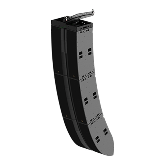
Page 24: Rigging System Description
Rigging system description Rigging system description L2/L2D The L2 system includes two enclosures: L2 and L2D. Each enclosure can be own or stacked alone, or assembled into a own array. The coverage of the array is achieved by the 10° curvature of the L2 enclosures, while the 60° curvature of L2D is designed to make it the last enclosure at the bottom of the array. - Page 25 Rigging system description The rigging elements and latches are tted with yellow safety labels that are visible when they are not safely locked. On both enclosures, seven inserts on each side provide further options such as ying with L2-RIGBAR as the main or pullback accessory, stacking on L2-CHARIOT/L2D-CHARIOT, securing L2-LASERMOUNT or L2-ROLL.
- Page 26 Two ergonomic handles on each side of the enclosures are available for handling. Dedicated chariots for L2/L2D L2 is intended for use only with L-Acoustics L2-CHARIOT. L2D is intended for use only with L-Acoustics L2D-CHARIOT. Use with other equipment may result in instability causing injury.
- Page 27 Rigging system description L2 and L2D feature cable clips at the rear to secure the SC32 cables. Two L2 at the top of an array One L2 and one L2D at the bottom of an array Risk of site angle modication Do not secure the SC32 cables to the rigging element.
-
Page 28: Rigging Elements
Rigging system description Rigging elements L2-BUMP L2-BUMP is a rigging frame designed for ying L2 and L2D. L2-BUMP can be used as the main lifting accessory for ying arrays of L2 with L2D, or a single L2D using the included two Ø19 mm shackles WLL 3.25 t and extension sling. - Page 29 Rigging system description L2-BUMP is equipped with four spring-loaded lock systems to match the rigging arms of L2 and L2D. Slide to unlock the spring-loaded lock. The rigging elements are tted with yellow safety labels that are visible when they are not safely locked. The central and side bars of L2-BUMP have four holes each for site angle adjustments.
-
Page 30: L2-Bar
Rigging system description L2-BAR L2-BAR is an extension bar that can be combined with L2-BUMP using two ball-locking pins. By adding L2-BAR to L2-BUMP, the site angle range can be increased. Seventeen holes are available on L2-BAR, which can be attached to L2-BUMP as a rear or a front extension and in position A or B, thus offering a total of 68 discrete positions for pickup points. -
Page 31: L2-Rigbar
Rigging system description L2-RIGBAR Secured at the bottom of the array using two ball-locking pins, L2-RIGBAR can be used as a pullback either with L2-BUMP combined with L2-BAR or another L2-RIGBAR as the main lifting accessory, to provide a lightweight solution for ying an L2 array. - Page 32 Rigging system description Secure L2-RIGBAR at the front for a positive initial site angle. Always implement a secondary safety using available holes. pickup point safety point safety points pickup points L2 owner's manual (EN) version 2.0...
-
Page 33: Delta 1.5T
Rigging system description DELTA 1.5T Combined with L2-BUMP and L2-BAR, DELTA 1.5T can be used to control the azimuth angle while L2-BAR controls the site angle. The recommended space between the two lifting points is 1 m / 3.3 ft. By adjusting the height of both pickup points, it is possible to adjust the azimuth angle from -10°... -
Page 34: La-Rakmount
Rigging system description LA-RAKMOUNT LA-RAKMOUNT is designed to stack one LA-RAK III on top of a own array. LA-RAKMOUNT is composed of two mounting cradles with rails. The two cradles are screwed on L2-BUMP. LA-RAKMOUNT must be used with two L2-BAR. L2 owner's manual (EN) version 2.0... -
Page 35: K2-Jack
Rigging system description K2-JACK K2-JACK is a set of two bars and four feet with screw jacks and hand wheels. K2-JACK can be tted onto L2-CHARIOT or L2D-CHARIOT to improve stability or to correct oor discrepancies. During transportation, make sure the bolts are tightened. hand wheels locking handles bolts (x4) -
Page 36: L2-Lasermount
Rigging system description L2-LASERMOUNT L2-LASERMOUNT is designed to secure a laser inclinometer to the inserts of L2 or L2D using a knob and a ball-locking pin. L2-LASERMOUNT is installed on one side of the enclosure depending on the availability of the insert for the ball-locking pin. -
Page 37: Storage And Handling
Rigging system description Storage and handling L2-ROLL As L2/L2D are delivered upside down, L2-ROLL can be used with L2-RIGBAR to reverse the enclosure and secure it on its chariot. It can also be used to turn L2/L2D upside down to perform maintenance procedures. Do not use L2-ROLL for rigging. -
Page 38: L2-Chariot
L2-CHARIOT is a chariot designed to transport one L2. It features four ball-locking pins to secure L2. Do not move or transport more than one L2 on L2-CHARIOT. L2-CHARIOT is intended for use only with L-Acoustics L2. Use with other equipment may result in instability causing injury. -
Page 39: L2D-Chariot
L2D-CHARIOT is a chariot designed to transport one L2D. It features six ball-locking pins to secure L2D. Do not move or transport more than one L2D on L2D-CHARIOT. L2D-CHARIOT is intended for use only with L-Acoustics L2D. Use with other equipment may result in instability causing injury. -
Page 40: L2-Chariotcov
Rigging system description L2-CHARIOTCOV L2-CHARIOTCOV is a protective cover for one L2 on L2-CHARIOT. L2-CHARIOTCOV features a ap at the back with a velcro fasterner to give access to L2 connector plate for identication. Do not use L2 with L2-CHARIOTCOV on, even with the front side lifted. The fabric is not acoustically neutral and is not compatible with the LC loudspeakers. -
Page 41: L2D-Chariotcov
Rigging system description L2D-CHARIOTCOV L2D-CHARIOTCOV is a protective cover for one L2D on L2D-CHARIOT. L2D-CHARIOTCOV features a ap at the back with a velcro fasterner to give access to L2D connector plate for identication. The ap features a red label to distinguish it from L2-CHARIOTCOV. Do not use L2D with L2D-CHARIOTCOV on, even with the front side lifted. -
Page 42: L2-Chariotlid
Rigging system description L2-CHARIOTLID L2-CHARIOTLID can be secured on top of L2 to store equipment during transportation. Its load capacity is up to 400 kg / 881.8 lb. Refer to Mounting L2-CHARIOTLID/L2D-CHARIOTLID on L2/L2D (p.81) procedure for more information. Multiple L2-CHARIOTLID can be stacked for storage (optionally with L2D-CHARIOTLID, and L2-CHARIOT/L2D-CHARIOT). Refer to Stacking multiple L2-CHARIOTLID/L2D-CHARIOTLID (p.85). -
Page 43: L2D-Chariotlid
Rigging system description L2D-CHARIOTLID L2D-CHARIOTLID can be secured on top of L2D to store equipment during transportation. Its load capacity is up to 400 kg / 881.8 lb. L2D-CHARIOTLID features red labels to distinguish it from L2-CHARIOTLID. Refer to Mounting L2-CHARIOTLID/L2D-CHARIOTLID on L2/L2D (p.81) procedure for more information. -
Page 44: L2-Bumpflight
Rigging system description L2-BUMPFLIGHT L2-BUMPFLIGHT is a ightcase for transporting the accessories of the L2 system. 1. 2 CLAMP1000-SINGLE 2. 2 BPCHAIN 1.5T / LA-SLING2T 3. 2 CLAMP1000-BASE 4. 2 L2-RIGBAR 5. 2 DELTA 1.5T 6. 2 CLAMP1000-DUAL (clamps open and towards the center) 7. -
Page 45: Mechanical Safety
Mechanical safety Mechanical safety Flown congurations The L2 rigging system complies with 2006/42/EC: Machinery Directive. It has been designed following the guidelines of BGV-C1. 2006/42/EC: Machinery Directive species a safety factor of 4 against the rupture. The own deployments described in this manual achieve a safety factor of 4 or more. - Page 46 Mechanical safety Assessing mechanical safety Mechanical safety of the rigging system Before any installation, always model the system in Soundvision and check the Mechanical Data section for any stress warning or stability warning. In order to assess the actual safety of any array conguration before implementation, refer to the following warnings: Rated working load limit (WLL) is not enough The rated WLL is an indication of the element resistance to tensile stress.
-
Page 47: Loudspeaker ConGurations
Loudspeaker congurations Loudspeaker congurations Line source Deployed as a line source, the system operates over the nominal bandwidth of the L2/L2D enclosure, with an adjustable horizontal directivity. All presets allow for a reference frequency response in long throw applications. Three congurations are possible : L2 line source, L2D line source, or L2/L2D line source. Two LF polar patterns are available: a cardioid pattern or a supercardioid pattern. -
Page 48: Line Source With Low-Frequency Element
Loudspeaker congurations Line source with low-frequency element A L2/L2D line source can be deployed with additional subwoofer enclosures to extend the bandwidth in the low-end or increase sub-low resources. The [L2 xxxxx] / [L2D xxxxx] presets deliver a reference frequency response in long throw applications with horizontal directivity settings and cardioid or supercardioid LF polar pattern. - Page 49 Loudspeaker congurations L2/L2D line source with KS28 beside 0.5 m to 1.5 m 1.6 ft to 5 ft Enclosure KS28 Preset [L2 70] [L2 90] [L2 110] [L2D 70] [L2D 90] [L2D 110] [KS28 L2] [L2 70_S] [L2 90_S] [L2 110_S] [L2D 70_S] [L2D 90_S] [L2D 110_S] Frequency range (-10 dB) 25 Hz - 20 kHz...
- Page 50 Loudspeaker congurations Pre-alignment delays L2/L2D + KS28 presets pre-alignment delay values and polarity settings [L2]/[L2D] + [KS28 L2] L2/L2D = 0 ms KS28 = 2.5 ms [L2]/[L2D] + [KS28_C L2] L2/L2D = 2.6 ms KS28 = 0 ms [L2]/[L2D] + [KS28_Cx L2] L2/L2D = 0 ms KS28 = 2.5 ms L2 owner's manual (EN) version 2.0...
-
Page 51: Rigging Procedures
Rigging procedures Rigging procedures Securing L2/L2D on L2-CHARIOT/L2D-CHARIOT Type of deployment stacking Rigging accessories L2-CHARIOT/L2D-CHARIOT L2-RIGBAR BPCHAIN 1.5T L2-ROLL Tools screwdriver 8 mm hex socket Min number of operators Do not use L2-ROLL for rigging. L2-ROLL is a temporary handling tool, not a long-term rigging accessory. Never position L2D on its narrow edge, even temporarily. - Page 52 Rigging procedures 2. On each side of the enclosure, remove the screw at the center of gravity. Use the screwdriver with a 8 mm hex socket. 8 mm Retain the screws for reassembly. 3. Tighten the L2-ROLL rings to the enclosure by hand. 4.
- Page 53 Rigging procedures 5. Secure the other ends of the straps to L2-RIGBAR through the ball-locking pins in their storage position. 6. Adjust the height so that the straps are taut but the enclosure is still on the ground. Make sure the straps are the same length on both sides, and are not twisted. L2 owner's manual (EN) version 2.0...
- Page 54 Rigging procedures 7. Slowly and carefully raise the enclosure about 40 cm / 1.33 ft from the ground. Remove the pallet and bottom lid of the delivery packaging. 8. Carefully turn around the enclosure by 180°. 9. Position L2-CHARIOT/L2D-CHARIOT underneath the assembly. 10.
- Page 55 Rigging procedures 11. Secure the L2-CHARIOT/L2D-CHARIOT ball-locking pins. 12. Unscrew the L2-ROLL rings from the enclosure by hand. L2 owner's manual (EN) version 2.0...
- Page 56 Rigging procedures 13. On each side of the enclosure, tighten the screw at the center of gravity. Use the screwdriver with a 8 mm hex socket. 8 mm L2 owner's manual (EN) version 2.0...
-
Page 57: Flying
Rigging procedures Flying Securing LA-RAK III on L2-BUMP with LA-RAKMOUNT Type of deployment own array Rigging accessories L2-BUMP LA-RAKMOUNT 8 M8×30 screws (provided with LA-RAKMOUNT) 2 L2-BAR 4 Ø19 mm shackles WLL 3.25 t Tools screwdriver T30 Torx bit Min number of operators Risk of falling objects Verify that no unattached items remain on the product or assembly. - Page 58 Rigging procedures L2-BAR can be attached to the L2-BUMP as a rear or a front extension and in position A or B. 3. Remove the coupling bars from LA-RAK III. Turn the spring-loaded safety mechanisms to release the bars and slide them out. 4.
- Page 59 Rigging procedures 5. Secure LA-RAK III with the coupling bars. Always insert the coupling bars so that the round safety mechanisms are pointed upward (depending on the site angle): from the back for a negative angle (rear extension) from the front for a positive angle (front extension) Insert the spring-loaded safety in the LA-RAK III rails, give a quarter turn and slide the bar until the safety locks into place.
-
Page 60: Flying An L2/L2D Array With L2-Bump And L2-Bar
Rigging procedures Flying an L2/L2D array with L2-BUMP and L2-BAR Type of deployment own array Rigging accessories L2-BUMP BPCHAIN 1.5T 1 or 2 L2-BAR (optional) 2 Ø19 mm shackles WLL 3.25 t + 2 Ø19 mm shackles WLL 3.25 t (if using a second L2-BAR) Min number of operators Risk of falling objects Verify that no unattached items remain on the product or assembly. - Page 61 Rigging procedures b) Pull on the front latches and rotate the rigging arms of the enclosure. The latches of L2-BUMP slide out slightly and come back into their positions. c) Press the front buttons on both sides of the enclosure to activate the automatic locking system. The latch retracts when the button is pushed (no yellow label visible).
- Page 62 Rigging procedures d) Pull on the rear latches of the enclosure while extending the rear rigging arms. Release the latches to lock the rigging arms in position. SHLAK! e) Press the buttons on both sides of L2-BUMP to activate the automatic locking system. The latch retracts when the button is pushed (no yellow label visible).
- Page 63 Rigging procedures b) Hold the chariot with one hand. Remove both back pins. c) Hold the chariot with one hand. Remove both front pins. 4. Raise the array. 5. Add more L2/L2D as necessary: a) Position the enclosure below the array. L2 owner's manual (EN) version 2.0...
- Page 64 Rigging procedures b) Lower the array until the ground runners of the top enclosure meet the matching tracks of the bottom enclosure at the front. L2 owner's manual (EN) version 2.0...
- Page 65 Rigging procedures c) Pull on the front latches and rotate the rigging arms of the bottom enclosure. The latches of the top enclosure slide out slightly and come back into their positions. SHLAK! SHLAK! SHLAK! SHLAK! L2 owner's manual (EN) version 2.0...
- Page 66 Rigging procedures d) Press the buttons on both sides of the bottom enclosure to activate the automatic locking system. The latch retracts when the button is pushed (no yellow label visible). e) Slightly raise the array so that the wheels are 30 cm / 1 ft from the ground. L2 owner's manual (EN) version 2.0...
- Page 67 Rigging procedures f) Turn the wheels inside the chariot. 30 cm / 1ft 30 cm / 1ft g) Pull on the rear latches of the bottom enclosure while extending the rear rigging arms. L2 owner's manual (EN) version 2.0...
- Page 68 Rigging procedures h) Press the buttons on both sides of the top enclosure to activate the automatic locking system. The latch retracts when the button is pushed (no yellow label visible). SHLAK! L2 owner's manual (EN) version 2.0...
- Page 69 Rigging procedures i) Pull back the bottom enclosure while lowering the array. The automatic locking system button locks and the latches engage. SHLAK! SHLAK! j) Repeat from step (p.62) to step (p.63) until the array is complete. L2 owner's manual (EN) version 2.0...
-
Page 70: Flying An L2/L2D Array With L2-Rigbar
Rigging procedures Flying an L2/L2D array with L2-RIGBAR Type of deployment own array Rigging accessories L2-RIGBAR 2 Ø19 mm shackles WLL 3.25 t Min number of operators Risk of falling objects Verify that no unattached items remain on the product or assembly. Additional safety for own arrays When ying an array, use available holes to implement a secondary safety. - Page 71 Rigging procedures 2. Secure L2-RIGBAR to the sling using Ø19 mm shackles WLL 3.25 t. Always implement a secondary safety using available holes. pickup point safety point safety points pickup points 3. Remove the chariot from the enclosure, raise the array, and add more L2/L2D as necessary. Refer to Flying an L2/L2D array with L2-BUMP and L2-BAR (p.60).
-
Page 72: Adding A Pullback With L2-Rigbar
Rigging procedures Adding a pullback with L2-RIGBAR Type of deployment own array Rigging accessories L2-RIGBAR 2 Ø19 mm shackles WLL 3.25 t Min number of operators Horizontal arrays Do not raise the rear pickup point above the front pickup point. Pickup points must be aligned with the linking points. - Page 73 Rigging procedures 3. Adjust the height of the pickup points. Under L2-BUMP Under L2-RIGBAR L2 owner's manual (EN) version 2.0...
-
Page 74: Stacking
Rigging procedures Stacking Attaching K2-JACK stabilizers to L2-CHARIOT/L2D-CHARIOT Type of deployment stacked array Rigging accessories K2-JACK L2-CHARIOT/L2D-CHARIOT Min number of operators Prerequisite Each L2/L2D is secured to its chariot. Securing L2/L2D on L2-CHARIOT/L2D-CHARIOT (p.51). Procedure 1. Attach the K2-JACK to the L2-CHARIOT/L2D-CHARIOT: a) Insert the K2-JACK studs through the chariot. - Page 75 Rigging procedures Dust During the K2-JACK stabilizers rst use, dust comes off the threaded rod. It is expected and does not indicate a malfunction. 2. Prepare the K2-JACK stabilizers. Rotate the threaded rod counter-clockwise so the central part of the stabilizer is closest to the base. 3.
- Page 76 Rigging procedures 4. Rotate the feet clockwise to raise the chariot off the ground. Stop raising the enclosure as soon as the wheels get off the ground. What to do next Adjust site angle using K2-JACK (refer to Adjusting L2-CHARIOT site angle with K2-JACK (p.77)), or using L2D- CHARIOT (refer to Adjusting L2D-CHARIOT site angle with K2-JACK...
-
Page 77: Adjusting L2-Chariot Site Angle With K2-Jack
Rigging procedures Adjusting L2-CHARIOT site angle with K2-JACK Type of deployment stacked array Rigging accessories K2-JACK L2-CHARIOT Min number of operators Prerequisite K2-JACK is secured to L2-CHARIOT/L2D- Attaching K2-JACK stabilizers to L2-CHARIOT/L2D-CHARIOT (p.74). CHARIOT. Procedure 1. Verify the wheels are as close as possible to the ground without touching it. Loosen the bolts by hand only. - Page 78 Rigging procedures Tipping hazard Adjust either the stabilizer at the front or at the back of the enclosure. Do not adjust both the front and back of the enclosure. 3. Adjust the site angle: Rotate the rear screw jacks for a negative site angle. Rotate the front screw jacks for a positive site angle.
-
Page 79: Adjusting L2D-Chariot Site Angle With K2-Jack
Rigging procedures Adjusting L2D-CHARIOT site angle with K2-JACK Type of deployment stacking Rigging accessories K2-JACK L2D-CHARIOT Min number of operators Tipping hazard Always install K2-JACK before setting the L2D-CHARIOT site angle. Attaching K2-JACK stabilizers to L2-CHARIOT/L2D-CHARIOT (p.74). Procedure Do not remove the ball-locking pins securing L2D to L2D-CHARIOT. 1. - Page 80 Rigging procedures 2. Tilt the enclosure and secure the ball-locking pins. at 0° at 8° at 12° at 20° L2 owner's manual (EN) version 2.0...
-
Page 81: Transporting
Rigging procedures Transporting Mounting L2-CHARIOTLID/L2D-CHARIOTLID on L2/L2D Type of deployment transporting Rigging accessories L2-CHARIOT/L2D-CHARIOT L2-CHARIOTLID/L2D-CHARIOTLID L2-CHARIOTCOV/L2D-CHARIOTCOV Min number of operators Prerequisite Each L2/L2D is secured to its chariot. Securing L2/L2D on L2-CHARIOT/L2D-CHARIOT (p.51). Procedure 1. Pull out the rigging arms: a) Pull on the latches while rotating the front rigging arms of the enclosure. - Page 82 Rigging procedures b) Pull on the latches while extending the rear rigging arms of the enclosure. Release the latches to lock the rigging arms in their upward positions. SHLAK! 2. Put L2-CHARIOTCOV on L2 or L2D-CHARIOTCOV on L2D. Open the top aps to let out the rigging arms. L2-CHARIOTCOV L2D-CHARIOTCOV features a red label.
- Page 83 Rigging procedures 3. Position L2-CHARIOTLID on L2 or L2D-CHARIOTLID on L2D: a) Tilt the lid towards the front to position the axes inside the front rigging arms. L2D-CHARIOTLID features red labels. b) Connect the rear rigging arms. The latches on the lid slide out slightly and come back into their positions. L2 owner's manual (EN) version 2.0...
-
Page 84: Stacking Multiple L2-Chariot/L2D-Chariot
Rigging procedures Stacking multiple L2-CHARIOT/L2D-CHARIOT Type of deployment storing Rigging accessories L2-CHARIOT/L2D-CHARIOT Min number of operators Stack the chariots in any direction and in any order, up to four chariots plus four chariotlids. What to do next Optionnally, stack L2-CHARIOTLID/L2D-CHARIOTLID on top. Refer to Stacking multiple L2-CHARIOTLID/L2D-CHARIOTLID (p.85). -
Page 85: Stacking Multiple L2-Chariotlid/L2D-Chariotlid
Rigging procedures Stacking multiple L2-CHARIOTLID/L2D-CHARIOTLID Type of deployment storing Rigging accessories L2-CHARIOTLID/L2D-CHARIOTLID Min number of operators Stack the lids front to back and back to front, in any order, up to four chariots plus four chariotlids. Bottom lid must be front to front with the L2-CHARIOT. Bottom lid can be in any direction on top of L2D-CHARIOT. -
Page 86: Connection To La AmpliEd Controllers
Connection to LA amplied controllers Connection to LA amplied controllers Refer to the Amplication reference technical bulletin for the latest information on compatibility with amplied controllers and cabling schemes for all enclosure types. Enclosure drive capacity per amplied controller LA7.16/LA7.16i per output / total Cabling schemes for L2 / L2D Refer to the cabling schemes to connect the enclosures to different types of output congurations. -
Page 87: Corrective Maintenance
— — * included in the L-Acoustics Maintenance Toolcase. Maintenance Toolcase The Maintenance Toolcase is a carry-on suitcase that includes all the tools required to perform maintenance on L- Acoustics products. This toolcase is aimed at Certied Providers. -
Page 88: Preparing Enclosures For Maintenance
Corrective maintenance Preparing enclosures for maintenance Most maintenance procedures require L2-CHARIOT/L2D-CHARIOT to be removed. This means that the enclosures, in particular L2D, may need to be turned upside-down using L2-ROLL. Rigging accessories • L2-RIGBAR • BPCHAIN 1.5T • L2-ROLL Tools •... - Page 89 Corrective maintenance 2. On each side of the enclosure, remove the screw at the center of gravity. Use the screwdriver with a 8 mm hex socket. 8 mm Retain the screws for reassembly. 3. Tighten the L2-ROLL rings to the enclosure by hand. 4.
- Page 90 Corrective maintenance 5. Secure the other ends of the straps to L2-RIGBAR through the ball-locking pins in their storage position. 6. Adjust the height so that the straps are taut but the enclosure is still on the ground. Make sure the straps are the same length on both sides, and are not twisted. 7.
- Page 91 Corrective maintenance 9. Carefully turn around the enclosure by 180°. 10. Position a mat underneath the assembly. 11. Carefully lower the assembly until the enclosure rests on the mat. 12. Unscrew the L2-ROLL rings from the enclosure by hand. What to do next To reverse L2/L2D after maintenance operations, refer to Securing L2/L2D on L2-CHARIOT/L2D-CHARIOT (p.51).
- Page 92 (p.104) • D/R - HF diaphragm (p.105) For advanced maintenance, contact your L-Acoustics representative. Exploded views In order to operate, follow the order outlined here. Each assembly refers to the corresponding Disassembly/Reassembly (D/R) procedure and the necessary repair kit. LF speaker...
- Page 93 Corrective maintenance LC speaker G03645 Side panel Grill HF diaphragm HF driver G03650 G03646 Connector plate Rear grill Trapdoors L2 owner's manual (EN) version 2.0...
- Page 94 Corrective maintenance Disassembly and Reassembly procedures D/R - Grill Tools • torque screwdriver • T20 Torx bit Repair kit G03645 - KR loudspeaker 12'' L2(D) G03647 - KR loudspeaker 10'' L2(D) ×4 S100156 M4×30 Torx Disassembly Procedure 1. Remove the four screws securing the grill. Use the torque screwdriver and the T20 Torx bit.
- Page 95 Corrective maintenance 2. Remove the grill. Reassembly About this task For safety reasons, always use the new screws and spare parts provided in the KR. If no new screws are available, use blue threadlocker. Procedure 1. Insert the side of the grill in the three tabs and push it into place. L2 owner's manual (EN) version 2.0...
- Page 96 Corrective maintenance 2. Tighten the four screws. Use the torque screwdriver and the T20 Torx bit. L2 owner's manual (EN) version 2.0...
- Page 97 Corrective maintenance D/R - Fin Tools • at plastic tool • torque screwdriver • T25 Torx bit Repair kit G03647 KR loudspeaker 10'' L2(D) ×6 S100228 M5x25 Torx Exploded view For safety reasons, always use the new screws and spare parts provided in the KR. If no new screws are available, use blue threadlocker.
- Page 98 Corrective maintenance D/R - LF speaker Tools • torque screwdriver • T25 Torx bit Repair kit G03647 KR loudspeaker 10'' L2(D) ×1 ×4 ×6 17995 102325 S100228 10" LF speaker -16 Ω 10" speaker gasket M5x25 Torx Prerequisite Grill removed. D/R - Grill (p.94).
- Page 99 Corrective maintenance D/R - Side panel Tools • torque screwdriver • T25 Torx bit Repair kit G03645 KR loudspeaker 12'' L2(D) ×24 S100302 M5×20 Torx Prerequisite Grill removed. D/R - Grill (p.94). Exploded view For safety reasons, always use the new screws and spare parts provided in the KR. If no new screws are available, use blue threadlocker.
- Page 100 Corrective maintenance D/R - LC speaker Tools • torque screwdriver • T30 Torx bit Repair kit G03645 KR loudspeaker 12'' L2(D) ×1 ×8 ×4 18177 S100143 1250 12" LF speaker M6×25 Torx 12" speaker gasket Prerequisite Grill removed. D/R - Grill (p.94).
- Page 101 Corrective maintenance D/R - Connector plate Tools • torque screwdriver • T25 Torx bit • at plastic tool Repair kit G03646 - KR compression driver 3" L2(D) G03650 - KR diaphragm 3'' L2(D) ×8 S100033 M5×25 Torx Exploded view For safety reasons, always use the new screws and spare parts provided in the KR. If no new screws are available, use blue threadlocker.
- Page 102 Corrective maintenance D/R - Rear grill Tools • torque screwdriver • T25 Torx bit Repair kit G03646 - KR compression driver 3" L2(D) G03650 - KR diaphragm 3'' L2(D) ×16 S100086 M5×16 Torx Exploded view For safety reasons, always use the new screws and spare parts provided in the KR. If no new screws are available, use blue threadlocker.
- Page 103 Corrective maintenance D/R - Trapdoors Tools • torque screwdriver • T25 Torx bit • at plastic tool Repair kit G03646 - KR compression driver 3" L2(D) G03650 - KR diaphragm 3'' L2(D) ×8 S100033 M5×25 Torx Prerequisite Rear grill removed. D/R - Rear grill (p.102).
- Page 104 Corrective maintenance D/R - HF driver Tools • torque screwdriver • T30 Torx bit Repair kit G03646 KR compression driver 3" L2(D) ×1 ×4 G100528 S100143 3" HF driver assembly - 8 Ω M6×25 Torx Prerequisite Connector plate removed. D/R - Connector plate (p.101).
- Page 105 Corrective maintenance D/R - HF diaphragm Tools • torque screwdriver • T20 Torx bit • compressed air blower Consumables • double face adhesive tape Repair kit G03650 KR diaphragm 3'' L2(D) ×1 ×4 18362 S18362 diaphragm assembly (with 2 shims) M4×14 Torx Prerequisite Connector plate removed.
-
Page 106: L2D
D/R - Connector plate (p.118) • D/R - Rear grill (p.119) • D/R - Trapdoors (p.120) • D/R - HF driver (p.121) • D/R - HF diaphragm (p.122) For advanced maintenance, contact your L-Acoustics representative. L2 owner's manual (EN) version 2.0... - Page 107 Corrective maintenance Exploded views In order to operate, follow the order outlined here. Each assembly refers to the corresponding Disassembly/Reassembly (D/R) procedure and the necessary repair kit. Turn L2D upside-down for maintenance Use L2-ROLL. Refer to Preparing enclosures for maintenance (p.88).
- Page 108 Corrective maintenance LC speaker G03645 Grill Side panel HF driver G03646 Trapdoors Rear grills Connector plate L2 owner's manual (EN) version 2.0...
- Page 109 Corrective maintenance HF diaphragm G03650 HF driver Trapdoors Rear grills Connector plate L2 owner's manual (EN) version 2.0...
- Page 110 Corrective maintenance Disassembly and Reassembly procedures D/R - Grill Tools • torque screwdriver • T20 Torx bit Repair kit G03645 - KR loudspeaker 12'' L2(D) G03647 - KR loudspeaker 10'' L2(D) ×4 S100156 M4×30 Torx Disassembly Procedure 1. Remove the four screws securing the grill. Use the torque screwdriver and the T20 Torx bit.
- Page 111 Corrective maintenance 2. Remove the grill. Reassembly About this task For safety reasons, always use the new screws and spare parts provided in the KR. If no new screws are available, use blue threadlocker. Procedure 1. Insert the side of the grill in the two tabs and push it into place. L2 owner's manual (EN) version 2.0...
- Page 112 Corrective maintenance 2. Tighten the four screws. Use the torque screwdriver and the T20 Torx bit. L2 owner's manual (EN) version 2.0...
- Page 113 Corrective maintenance D/R - Fin Tools • at plastic tool • torque screwdriver • T25 Torx bit Repair kit G03647 KR loudspeaker 10'' L2(D) ×6 S100228 M5x25 Torx Exploded view For safety reasons, always use the new screws and spare parts provided in the KR. If no new screws are available, use blue threadlocker.
- Page 114 Corrective maintenance D/R - Fixed n Tools • torque screwdriver • T25 Torx bit Repair kit G03647 KR loudspeaker 10'' L2(D) ×2 ×2 S100108 S158 M5×45 hex plain washer Ø5 mm Prerequisite Grill removed. D/R - Grill (p.110). Exploded view For safety reasons, always use the new screws and spare parts provided in the KR. If no new screws are available, use blue threadlocker.
- Page 115 Corrective maintenance D/R - LF speaker Tools • torque screwdriver • T25 Torx bit Repair kit G03647 KR loudspeaker 10'' L2(D) ×1 ×4 ×6 17995 102325 S100228 10" LF speaker -16 Ω 10" speaker gasket M5x25 Torx Prerequisite Grill removed. D/R - Grill (p.110).
- Page 116 Corrective maintenance D/R - Side panel Tools • torque screwdriver • T25 Torx bit Repair kit G03645 KR loudspeaker 12'' L2(D) ×24 S100302 M5×20 Torx Prerequisite Grill removed. D/R - Grill (p.110). Exploded view For safety reasons, always use the new screws and spare parts provided in the KR. If no new screws are available, use blue threadlocker.
- Page 117 Corrective maintenance D/R - LC speaker Tools • torque screwdriver • T30 Torx bit Repair kit G03645 KR loudspeaker 12'' L2(D) ×1 ×8 ×4 18177 S100143 1250 12" LF speaker M6×25 Torx 12" speaker gasket Prerequisite Grill removed. D/R - Grill (p.110).
- Page 118 Corrective maintenance D/R - Connector plate Tools • torque screwdriver • T25 Torx bit • at plastic tool Repair kit G03646 - KR compression driver 3" L2(D) G03650 - KR diaphragm 3'' L2(D) ×16 S100086 M5×16 Torx Exploded view For safety reasons, always use the new screws and spare parts provided in the KR. If no new screws are available, use blue threadlocker.
- Page 119 Corrective maintenance D/R - Rear grill Tools • torque screwdriver • T25 Torx bit Repair kit G03646 - KR compression driver 3" L2(D) G03650 - KR diaphragm 3'' L2(D) ×16 S100086 M5×16 Torx Exploded view For safety reasons, always use the new screws and spare parts provided in the KR. If no new screws are available, use blue threadlocker.
- Page 120 Corrective maintenance D/R - Trapdoors Tools • torque screwdriver • T25 Torx bit • at plastic tool Repair kit G03646 - KR compression driver 3" L2(D) G03650 - KR diaphragm 3'' L2(D) ×16 S100086 M5×16 Torx Prerequisite Rear grill removed. D/R - Rear grill (p.119).
- Page 121 Corrective maintenance D/R - HF driver Tools • torque screwdriver • T30 Torx bit Repair kit G03646 - KR compression driver 3" L2(D) G03650 - KR diaphragm 3'' L2(D) ×1 ×4 G100528 S100143 3" HF driver assembly - 8 Ω M6×25 Torx Prerequisite Connector plate removed.
- Page 122 Corrective maintenance D/R - HF diaphragm Tools • torque screwdriver • T20 Torx bit • compressed air blower Consumables • double face adhesive tape Repair kit G03650 KR diaphragm 3'' L2(D) ×1 ×4 18362 S18362 diaphragm assembly (with 2 shims) M4×14 Torx Prerequisite Connector plate removed.
- Page 123 Corrective maintenance Reassembly About this task For safety reasons, always use the new screws and spare parts provided in the KR. Procedure 1. Clean the dome and the air gap. Make sure the air gap is perfectly clean before reassembly. Use a blower or double face adhesive to remove any particle.
-
Page 124: SpeciCations
Specications Specications L2 specications Description 16-channel active progressive curvature WST 10° enclosure: 4 × 12" LC + 8 × 10" LF + 8 × 3" HF amplied by LA7.16 / LA7.16i Usable bandwidth 45 Hz - 20 kHz Maximum SPL entire enclosure module 1 only 155 dB ([L2 70]) - Page 125 Specications L2 dimensions 850 mm / 33.5 in L2 owner's manual (EN) version 2.0...
-
Page 126: L2D
Specications L2D specications Description 16-channel active progressive curvature WST 60° enclosure: 4 × 12" LC + 8 × 10" LF + 8 × 3" HF amplied by LA7.16 / LA7.16i Usable bandwidth 45 Hz - 20 kHz Maximum SPL entire enclosure module 1 only 151 dB ([L2D 70]) 147 dB ([L2D 70]) - Page 127 Specications L2D dimensions 850 mm / 33.5 in L2 owner's manual (EN) version 2.0...
-
Page 128: Ks28
Specications KS28 specications Description Flyable subwoofer 2 × 18", amplied by LA12X / LA2Xi Low frequency limit (-10 dB) 25 Hz ([KS28_100]) Maximum SPL 143 dB ([KS28_100]) with LA2Xi (bridge mode) / LA12X 136 dB ([KS28_100]) with LA2Xi Directivity standard or cardioid Transducers 2 ×... - Page 129 Specications KS28 dimensions 702 mm / 27.6 in 1340 mm / 52.8 in 1351 mm / 53.2 in L2 owner's manual (EN) version 2.0...
-
Page 130: L2-Bump
Specications L2-BUMP specications Description Flying frame for L2 and L2D (incl. 1 extension sling + 1 laser adapter) 2 × Ø19 mm shackles WLL 3.25 t Weight (net) 25 kg / 55 lb Material high grade steel with anti-corrosion coating L2-BUMP dimensions 845 mm / 33.3 in L2 owner's manual (EN) version 2.0... -
Page 131: L2-Bar
Specications L2-BAR specications Description Extension bar for L2-BUMP 2 Ø19 mm shackles WLL 3.25 t Weight (net) 16 kg / 35 lb Material high grade steel with anti-corrosion coating L2-BAR dimensions 1014 mm / 39.9 in 65 mm / 2.6 in L2 owner's manual (EN) version 2.0... -
Page 132: L2-Rigbar
Specications L2-RIGBAR specications Description Rigging bar and pullback for L2 and L2D 2 × Ø19 mm shackles WLL 3.25 t Weight (net) 7.7 kg / 17 lb Material high grade steel with anti-corrosion coating L2-RIGBAR dimensions 923 mm / 36.3 in L2 owner's manual (EN) version 2.0... -
Page 133: La-Rakmount
Specications LA-RAKMOUNT specications Description Mounting cradles for racks, including screws Weight (net) 7 kg / 15 lb Material high grade steel with anti-corrosion coating LA-RAKMOUNT dimensions 162 mm / 6.4 in 60 mm / 2.4 in L2 owner's manual (EN) version 2.0... -
Page 134: Bpchain 1.5T
Specications BPCHAIN 1.5T specications Description Extension sling 1.5 tons (included in K3-BUMP) Weight (net) 4 kg / 9 lb Material high grade steel with anti-corrosion coating BPCHAIN 1.5T dimensions 1280 mm / 50.4 in 19 mm / 0.7 in 98 mm / 3.8 in 19 mm / 0.7 in 112 mm / 4.4 in L2 owner's manual (EN) version 2.0... -
Page 135: K2-Jack
Specications K2-JACK specications Description 4 tilt adjustment screw jacks + 2 bars for chariots Weight (net) 10.1 kg / 22.3 lb (for one stabilizer) Material high grade steel with anti-corrosion coating K2-JACK dimensions 1278 mm / 50.3 in 124 mm / 4.9 in L2 owner's manual (EN) version 2.0... -
Page 136: L2-Lasermount
Specications L2-LASERMOUNT specications Description Lasermount for L2 and L2D Weight (net) 1 kg / 2 lb Material high grade steel with anti-corrosion coating L2-LASERMOUNT dimensions 85 mm / 3.3 in 123 mm / 4.8 in L2 owner's manual (EN) version 2.0... -
Page 137: Delta 1.5T
Specications DELTA 1.5T specications Description Azimuth angle tuning accessory 1.5T Weight (net) 8 kg / 18 lb Material high grade steel with anti-corrosion coating DELTA 1.5T dimensions 606 mm / 23.9 in 41 mm / 1.6 in 23 mm / 0.9 in L2 owner's manual (EN) version 2.0... -
Page 138: L2-Chariot
Specications L2-CHARIOT specications Description Chariot for one L2 Weight (net) 32 kg / 70 lb Material high grade steel with anti-corrosion coating L2-CHARIOT dimensions 1098 mm / 43.2 in L2 owner's manual (EN) version 2.0... -
Page 139: L2D-Chariot
Specications L2D-CHARIOT specications Description Chariot for one L2D Weight (net) 33 kg / 72 lb Material high grade steel with anti-corrosion coating L2D-CHARIOT dimensions 1098 mm / 43.2 in L2 owner's manual (EN) version 2.0... - Page 140 Specications L2-CHARIOTLID specications Description Protective lid for L2-CHARIOT Weight (net) 15 kg / 33 lb Material high grade steel with anti-corrosion coating L2-CHARIOTLID dimensions 1092 mm / 43 in L2 owner's manual (EN) version 2.0...
- Page 141 Specications L2D-CHARIOTLID specications Description Protective lid for L2D-CHARIOT Weight (net) 14 kg / 31 lb Material high grade steel with anti-corrosion coating L2D-CHARIOTLID dimensions 1092 mm / 43 in L2 owner's manual (EN) version 2.0...
-
Page 142: Appendix A: Recommendation For Speaker Cables
8 Ω load 4 Ω load 2.7 Ω load Use the more detailed L-Acoustics calculation tool to evaluate cable length and gauge based on the type and number of enclosures connected. The calculation tool is available on our website: https://www.l-acoustics.com/installation-tools/... -
Page 143: Appendix B: Installing A Laser Inclinometer
Installing a laser inclinometer Installing a laser inclinometer L2-LASERMOUNT L2-LASERMOUNT can be used to secure a laser inclinometer vertically or horizontally, using the L-Acoustics Tech Toolcase II accessories. With LASER-MAGPLATE Mount the inclinometer on the LASER-MAGPLATE: Position the magnetic LASER-MAGPLATE on L2-LASERMOUNT:... -
Page 144: L2-Bump
Installing a laser inclinometer Horizontal mount, with the bracket L2-BUMP L2-BUMP can accommodate a laser inclinometer, using the L-Acoustics Tech Toolcase II accessories. With LASER-MAGPLATE With screws L2 owner's manual (EN) version 2.0... - Page 145 L-Acoustics 13 rue Levacher Cintrat - 91460 Marcoussis - France +33 1 69 63 69 63 - info@l-acoustics.com www.l-acoustics.com...
Need help?
Do you have a question about the L Series and is the answer not in the manual?
Questions and answers