Table of Contents
Advertisement
Quick Links
Advertisement
Table of Contents

Related Manuals for L-Acoustics KIVA II


Summary of Contents for L-Acoustics KIVA II
- Page 1 KIVA II owner's manual (EN)
- Page 2 Document reference: Kiva II owner's manual (EN) version 1.0 Distribution date: December 17, 2018 © 2018 L-Acoustics. All rights reserved. No part of this publication may be reproduced or transmitted in any form or by any means without the express written consent of the publisher.
-
Page 3: Table Of Contents
Contents Safety................................5 Instructions..............................5 Symbols..............................6 Introduction................................ 7 How to use this manual..........................7 Kiva II ultra-compact modular line source....................7 System components.............................8 Loudspeaker cables........................... 9 Rigging elements............................9 Electro-acoustical description..........................10 Directivity............................... 10 Preset description............................ 11 Connectors............................. 12 Rigging system description..........................13 Kiva II..............................13... - Page 4 Back cover inspection........................44 Rigging check............................45 Acoustical check............................. 48 Rigging procedures............................52 Flying..............................52 Flying a Kiva II array........................52 Flying a Kiva II / SB15m array......................58 Adding a pull-back under Kiva II....................64 Ceiling-mounting Kiva II......................... 67 Disassembly..........................70 Stacking..............................73 Pole-mounting............................79 Loudspeaker connection............................
-
Page 5: Safety
Respect the Working Load Limit (WLL) of third party equipment. L-Acoustics is not responsible for any rigging equipment and accessories provided by third party manufacturers. Verify that the Working Load Limit (WLL) of the suspension points, chain hoists and all additional hardware rigging accessories is respected. -
Page 6: Symbols
This symbol noties the user about instructions that must be strictly followed to ensure proper installation or operation of the product. This symbol noties the user about complementary information or optional instructions. Kiva II owner's manual (EN) version 1.0... -
Page 7: Introduction
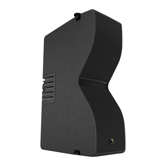
The cabinet is made of a new composite material, with a high immunity to moisture and shocks and remarkable acoustic properties. Kiva II weighs a mere 14 kg (31 lb) and its compact elegance makes for an easy integration in any situation. -
Page 8: System Components
Rigging frame for ying Kiva II/Kiva KIBU-SB Rigging frame for ying or stacking KIVA II/KIVA and SB15m KIET II Rigging plate for ceiling or pole-mount of 3 KIVA II/KIVA maximum KIVA-PULLBACK Pullback accessory for KIVA II/KIVA L-Case 2U Electronics transport and protection case... -
Page 9: Loudspeaker Cables
SP.7 / SP5 / SP10 / SP25 SP-Y1 SPK1 SPK2 0.7 m / 10 m / 25 m SPK3 SPK4 DO.7 / DO10 / DO25 DOSUB-LA8 Rigging elements KIET II KIVA-PULLBACK KIBU-SB KIBU II Kiva II owner's manual (EN) version 1.0... -
Page 10: Electro-Acoustical Description
Electro-acoustical description Electro-acoustical description Directivity Kiva II features a V-shaped transducer arrangement coupled with a DOSC waveguide that generates a horizontal directivity pattern of 100°. Kiva II beamwidth -100 -120 -140 -160 -180 1000 10 000 Frequency (Hz) Dispersion angle diagram of an array of six enclosures with 0° inter-enclosure angle, using lines of equal sound pressure at -3 dB, -6 dB, -12 dB. -
Page 11: Preset Description
OUT 4 IN A 0 dB 0 ms [SB18_60_C] [SB15_100_C] loudspeaker elements outputs channels routing gain delay polarity mute OUT 1 IN A 0 dB 0 ms OUT 2 OUT 3 OUT 4 Kiva II owner's manual (EN) version 1.0... -
Page 12: Connectors
Electro-acoustical description Connectors Kiva II is equipped with two 4-point speakON connectors. Kiva II LINK Internal pinout for L-Acoustics 2-way passive enclosures speakON points Transducer connectors + Not linked Not linked SB15m is equipped with two 4-point speakON connectors. SB18 is equipped with two 4-point speakON connectors. -
Page 13: Rigging System Description
The front linking points are locked with a spring-loaded safety mechanism inside the right handle. A yellow safety label is visible if the mechanism is not fully engaged. On every Kiva II, check that the logo is on the same side as the safety mechanism (identiable by the eyelet and the handle shape). - Page 14 Rigging system description Kiva II can be connected to other Kiva II or to dedicated rigging accessories. The inter-enclosure angle can be set between 0° and 15°. Kiva II owner's manual (EN) version 1.0...
-
Page 15: Subwoofers
The coupling bars can be stored on both sides on the storage pins. The locking tabs slide inside the coupling bars to keep them in place. CLICK ! The locking tabs lugs t into notches. A yellow safety label is visible if the locking tabs are not fully engaged. Kiva II owner's manual (EN) version 1.0... -
Page 16: Sb18 / Sb18I / Sb18M
For more information on rigging SB18, refer to the SB18 rigging manual. SB18 has a four-point rigging system with two rigging arms and two pins on each side. storage position rigging position rigging arm (x4) pin (x4) Kiva II owner's manual (EN) version 1.0... - Page 17 For more information on rigging SB18m, refer to the SB18m rigging manual. SB18m features four rigging rails on top and bottom faces. Connection with other elements is ensured by two coupling bars with locking tabs. rigging rails locking tabs coupling bars rigging rails Kiva II owner's manual (EN) version 1.0...
- Page 18 CLICK ! The locking tabs lugs t into notches. A yellow safety label is visible if the locking tabs are not fully engaged. Two stacking runners meet two runner tracks in stacked deployments. Kiva II owner's manual (EN) version 1.0...
- Page 19 Rigging system description SB18, SB18m, and SB18i feature a 35 mm pole socket. Kiva II owner's manual (EN) version 1.0...
-
Page 20: Rigging Elements
KIBU-SB Kiva II/SB15m rigging interface KIBU-SB is a rigging interface to connect Kiva II to SB15m. Each side of the rigging structure is designed to t one enclosure type. One side is compatible with the Kiva II three-point rigging system. - Page 21 Kiva II in rear position with a positive 7.5° angle The positive 7.5° angle is only available when Kiva II and KIBU-SB are stacked on SB15m. When Kiva II and KIBU-SB are ground-stacked, the rigging arm cannot be secured at 7.5°.
-
Page 22: Kiet Ii
KIET II features two dedicated rear linking points, one for pole-mounting and one for ceiling-mounting deployment. Pole-mount KIET II is a rigging accessory compatible with the Kiva II rigging system. It is delivered with a removable 35 mm pole socket. It can be used to mount up to three Kiva II on a pole. -
Page 23: Kiva-Pullback
KIBU II Flying frame KIBU II is a rigging structure designed to t the Kiva II rigging system in own conguration. 13 pickup points are available. 0 1 2 3 4 5 6 7 8 9 10 11 12 13... -
Page 24: Mechanical Safety
Mechanical safety Flown congurations The Kiva II rigging system complies with 2006/42/EC: Machinery Directive. It has been designed following the guidelines of BGV-C1. 2006/42/EC: Machinery Directive species a safety factor of 4 against the rupture. The own deployments described in this manual achieve a safety factor of 4 or higher. - Page 25 Soundvision calculations are based on usual environmental conditions. A higher safety factor is recommended with factors such as extreme high or low temperatures, strong wind, prolonged exposition to salt water, etc. Always consult a rigging specialist to adopt safety practices adapted to such a situation. Kiva II owner's manual (EN) version 1.0...
-
Page 26: Loudspeaker ConGurations
In this conguration the system operates over the nominal bandwidth of the enclosure. The [KIVA II] preset allows for a reference frequency response in medium to long throw applications. Kiva II is driven by the LA12X / LA4X / LA8 amplied controllers. -
Page 27: With Low-Frequency Element
Kiva II line source with low-frequency element In this conguration, the bandwidth of the Kiva II system is extended in the low end and the LF contour is reinforced. The [KIVA II] preset allows for a reference frequency response in medium to long throw applications. - Page 28 Kiva II line source with SB15m and SB18 With SB15m and SB18, the system bandwidth is extended down to 32 Hz. 3 Kiva II : 1 SB15m : 1 SB18 2 Kiva II : 1 SB15m : 1 SB18 reinforced contour...
-
Page 29: Kiva Ii Line Source Element
Loudspeaker congurations Kiva II line source element Up to three Kiva II can be used as a line source element. In this conguration, the system operates over the nominal bandwidth of Kiva II. The [KIVA II_FI] preset allows for a reference frequency response in short throw applications. -
Page 30: With Low-Frequency Element
Kiva II line source element with low-frequency element Up to three Kiva II can be used as a line source element with a complementary subwoofer. In this conguration, the system bandwidth is extended in the low end and the LF contour is reinforced. -
Page 31: Inspection And Preventive Maintenance
Critical parts of the lifting chains are highlighted. indicates a visual inspection. The indicates a functional check. Perform the Rigging part inspection (p.37) on critical parts. For each part, use the inspection references indicated over the preview illustration. Kiva II owner's manual (EN) version 1.0... - Page 32 Inspection and preventive maintenance Mixed Kiva II array with SB15m and KIBU-SB Refer to Rigging part inspection (p.37). Rigging rails, storage pins (p.41) Shackles (p.43) Rigging rails, storage pins (p.41) Coupling bars, locking tabs (p.38) Coupling bars, locking tabs (p.38) Ball-locking pins (p.39)
- Page 33 Inspection and preventive maintenance Kiva II array with KIBU II and KIVA-PULLBACK Refer to Rigging part inspection (p.37). Shackles (p.43) Ball-locking pins (p.39) Rigging axis, lodging (p.42) Rigging check (p.45) CLICK ! Rigging axis, lodging (p.42) Back cover inspection (p.44)
- Page 34 Rigging part inspection (p.37). Ball-locking pins (p.39) Rigging axis, lodging (p.42) Rigging check (p.45) CLICK ! Rigging axis, lodging (p.42) Back cover inspection (p.44) logo on the same side as the safety mechanism Kiva II owner's manual (EN) version 1.0...
- Page 35 Inspection and preventive maintenance Kiva II pole-mounted on SB15m with KIET II Refer to Rigging part inspection (p.37). Back cover inspection (p.44) Rigging check (p.45) CLICK ! Rigging axis, lodging (p.42) logo on the same side as the safety mechanism Ball-locking pins (p.39)
- Page 36 Ball-locking pins (p.39) SB18i screws are tightened screws are tightened tabs are not bent screws are tightened SB18m Rigging rails, storage pins (p.41) screws are tightened Coupling bars, locking tabs (p.38) Kiva II owner's manual (EN) version 1.0...
-
Page 37: Rigging Part Inspection
Place the rigging part on a at surface or hold a level against it. 5. Check the moving parts. Make sure that the mechanism engages correctly. What to do next If a problem is detected, perform the authorized maintenance operations or contact your L-Acoustics representative. Kiva II owner's manual (EN) version 1.0... -
Page 38: Inspection References
KR WIFOVER (Kit 2 locking tabs with slings ) Locking tabs (p.127) SB18m KR WIFOVER (Kit 2 locking tabs with slings ) *: contact your L-Acoustics representative Related tasks Rigging part inspection (p.37) Kiva II owner's manual (EN) version 1.0... - Page 39 Ball-locking pins Reference pictures tether (KIET II) tether (KIBU-SB) tether (KIBU II) Moving parts 1. Press the push button. The ball-locking mechanism is retracted. 2. Release the button. The ball-locking mechanism is activated. Kiva II owner's manual (EN) version 1.0...
- Page 40 3. Insert the pin in its storage and rigging locations. If the pin in inserted in two plates, the ball must pass between both plates and lock the pin in place. If the check fails, immediately withdraw the product from use and contact L-Acoustics. Repair kits (KR)
- Page 41 SB15m KR WIFOPION (Kit 4 pins for coupling bars in storage mode) SB18m KR WIFOPION (Kit 4 pins for coupling bars in storage mode) KIBU-SB on demand Related tasks Rigging part inspection (p.37) Kiva II owner's manual (EN) version 1.0...
- Page 42 Repair kits Contact your L-Acoustics representative for repair instructions. Rigging axis Kiva II G03307 (KR rigging axes KIVA II (x2) ) KIBU-SB KR CVKIRIGAXE (Kit 10 rigging axe & screws ) KIET II G03307 (KR rigging axes KIVA II (x2) )
- Page 43 KR CAMAN12 (Kit 4 straight shackles 12 mm ) KIVA-PULLBACK KR CAMAN12 (Kit 4 straight shackles 12 mm ) KIBU II KR CAMAN12 (Kit 4 straight shackles 12 mm ) Related tasks Rigging part inspection (p.37) Kiva II owner's manual (EN) version 1.0...
-
Page 44: Back Cover Inspection
Inspection and preventive maintenance Back cover inspection About this task In order to assess the deformation of the back cover of Kiva II, inspect the back cover on every single enclosure. Take down the enclosure before inspection. Procedure — Check the rigging pin holes for signs of ovalization. -
Page 45: Rigging Check
Inspection and preventive maintenance Rigging check Procedure 1. Secure one Kiva II on top of a second one (logos on the left). CLICK ! • The safety clicks back into place. • Both rigging axis t in their lodgings. • The yellow label is not visible at all on the logo side. - Page 46 3. Hold the top enclosure by the handles and shake the assembly. The two enclosures remain attached. 4. Release the rigging arm of the top enclosure. Risk of trapping hand/ngers Carefully release the back of the enclosure until it rests on the assembly. Kiva II owner's manual (EN) version 1.0...
- Page 47 Inspection and preventive maintenance 5. Unlock the mechanism inside the left handle of the top enclosure and slide the enclosure to the left. 6. Switch the enclosures and repeat the procedure. Kiva II owner's manual (EN) version 1.0...
-
Page 48: Acoustical Check
6. Press the OK key or the encoder wheel to launch the ENCLOSURE CHECK. The amplied controller generates short sinusoidal signals simultaneously for each connected output. The amplied controller displays the results for each output. Kiva II owner's manual (EN) version 1.0... - Page 49 • a percentage of variation from the expected range (found in NOK and UNDEF results) • the number of operational transducers out of the total Low variations from the expected range are acceptable: displayed percentage can be different from 0 and all transducers considered operational. Kiva II owner's manual (EN) version 1.0...
- Page 50 • The diaphragm is damaged. Procedure 1. Perform the diaphragm disassembly procedure. 2. Visually inspect the diaphragm and the voice coil. If any damage is visible, replace the diaphragm. 3. Clean the air gap thoroughly. Kiva II owner's manual (EN) version 1.0...
- Page 51 Inspection and preventive maintenance 4. Perform the reassembly procedure. Pay close attention to the position of the diaphragm. Apply the recommended torque. 5. Repeat the listening test. Kiva II owner's manual (EN) version 1.0...
-
Page 52: Rigging Procedures
Risk of falling objects Verify that no unattached items remain on the array. On every Kiva II, check that the logo is on the same side as the safety mechanism (identiable by the eyelet and the handle shape). Pickup point for pullback deployment Use hole 13 on KIBU II. - Page 53 Rigging procedures Assembly Procedure 1. Bring a stack of four Kiva II (logos on the right-hand side) under the lifting point. All angles must be at 0°. 2. Secure the rigging frame on top of the stack. - With KIBU-SB Use the front or rear position.
- Page 54 The yellow label is not visible on the logo side. Shake the assembly up and down and from side to side to verify that all linking points are secured. 3. Choose the pickup point(s) and y the assembly. Kiva II owner's manual (EN) version 1.0...
- Page 55 Align the mark on the rigging arm with the chosen angle mark. 7.5° SHLAK ! 5. Bring a second stack of four Kiva II (logos on the right-hand side) under the array. All angles must be at 0°. Kiva II owner's manual (EN) version 1.0...
- Page 56 Shake the assembly up and down and from side to side to verify that all linking points are secured. Do not stand behind the array. The array swings backward when it is raised. 7. Raise the assembly. Kiva II owner's manual (EN) version 1.0...
- Page 57 Do not use this method for an array bigger than eight enclosures. Any additionnal enclosure must be connected one by one as follows. 9. Connect a Kiva II (logo on the right-hand side) under the array. CLICK ! Set the inter-enclosure angle.
-
Page 58: Flying A Kiva Ii / Sb15M Array
Risk of falling objects Verify that no unattached items remain on the array. On every Kiva II, check that the logo is on the same side as the safety mechanism (identiable by the eyelet and the handle shape). Pickup point for pullback deployment Use hole 13 on KIBU-SB for SB15m. - Page 59 4. Lower the array until it rests on the subwoofer 5. Secure the SB15m under the array. Use the coupling bars from the top subwoofer. Secure the coupling bars with the locking tabs. Kiva II owner's manual (EN) version 1.0...
- Page 60 6. Repeat steps (p.59) to (p.59) until the subwoofer array is complete. 7. Secure a Kiva II (logo on the left-hand side) on a KIBU-SB (coupling bars removed). - Front position CLICK ! Select the 0° angle on the rigging arm.
- Page 61 Shake the assembly up and down and from side to side to verify that all linking points are secured. 8. Turn the assembly upside-down and secure it under the SB15m array with coupling bars. Secure the coupling bars with the locking tabs. Kiva II owner's manual (EN) version 1.0...
- Page 62 CLICK ! Make sure the safety label on each locking tab is fully covered. Make sure the lugs are in the notches. 9. Connect a Kiva II (logo on the right-hand side) under the array. CLICK ! Set the inter-enclosure angle.
- Page 63 SHLAK ! Final check The yellow label is not visible on the logo side. Shake the assembly up and down and from side to side to verify that all linking points are secured. Kiva II owner's manual (EN) version 1.0...
-
Page 64: Adding A Pull-Back Under Kiva Ii
The space between the two lifting points must be aligned with the array pickup points. The deployment load-bearing lines must be parallel to each other. On every Kiva II, check that the logo is on the same side as the safety mechanism (identiable by the eyelet and the handle shape). - Page 65 Assembly Procedure 1. Secure a KIVA-PULLBACK under the bottom enclosure. Rotate the accessory to nd the correct locking position. Secure the rear piece in the spring-lock safety of the bottom enclosure. SHLAK ! Kiva II owner's manual (EN) version 1.0...
- Page 66 The yellow label is not visible on the logo side. Shake the assembly up and down and from side to side to verify that all linking points are secured. 2. Secure a shackle to KIVA-PULLBACK and lift it with an additional motor. Kiva II owner's manual (EN) version 1.0...
-
Page 67: Ceiling-Mounting Kiva Ii
3 M8 spacers (provided) 3 M8 screws (depending on the ceiling material) min number of operators On every Kiva II, check that the logo is on the same side as the safety mechanism (identiable by the eyelet and the handle shape). Assembly Procedure 1. - Page 68 Rigging procedures 2. Secure Kiva II (logo on the right-hand side) under KIET II. CLICK ! Select the site angle on the rigging arm. Use the applicable rear linking point, as illustrated. -5.3° -4.1° -3° -1.8° -0.5° +0.9° +5.2° Final check The yellow label is not visible on the logo side.
- Page 69 Rigging procedures 3. Connect a Kiva II (logo on the right-hand side) under the array. CLICK ! Set the inter-enclosure angle. Align the mark on the rigging arm with the chosen angle mark. 7.5° SHLAK ! Final check The yellow label is not visible on the logo side.
-
Page 70: Disassembly
1. Release the rigging arm of the bottom enclosure. Slightly lift the enclosure if necessary. Risk of fall Carefully lower the rear of the enclosure. 2. Release the enclosure. Slightly lift the rear of the enclosure if necessary. Kiva II owner's manual (EN) version 1.0... - Page 71 Rigging procedures Removing a stack of four Kiva II About this task Use this method for an array of eight or less Kiva II. Any additional enclosure must be removed one by one. Minimum number of operators: 2 Procedure Hold the bottom enclosure at all times.
- Page 72 Rigging procedures 3. Release the rigging arm of the upper enclosure to disconnect the stack at the rear. 4. Release the top enclosure. 5. Raise the array and put the stack aside. Kiva II owner's manual (EN) version 1.0...
-
Page 73: Stacking
Any of the following subwoofer arrays can be set in cardioid conguration. Assembly About this task To ground-stack Kiva II on KIBU-SB, start at step (p.74). Procedure 1. Prepare a stack of SB15m. Secure the coupling bars with the locking tabs. - Page 74 Make sure the lugs are in the notches. 3. Secure Kiva II (logo on the left-hand side) on KIBU-SB (coupling bars removed). For optimal stability, prefer the rear position for a front-tilting array and the front position for a rear-tilting array.
- Page 75 Rigging procedures CLICK ! Select the site angle on the rigging arm. 0° -1° -2° - Rear position CLICK ! Select the site angle on the rigging arm. Kiva II owner's manual (EN) version 1.0...
- Page 76 Kiva II in rear position with a positive 7.5° angle The positive 7.5° angle is only available when Kiva II and KIBU-SB are stacked on SB15m. When Kiva II and KIBU-SB are ground-stacked, the rigging arm cannot be secured at 7.5°.
- Page 77 The yellow label is not visible on the logo side. Shake the assembly up and down and from side to side to verify that all linking points are secured. 5. Repeat the previous step until the array is complete. Kiva II owner's manual (EN) version 1.0...
- Page 78 Carefully release the back of the enclosure until it rests on the assembly. 2. Unlock the mechanism inside the left handle of the top enclosure and slide the enclosure to the left. 3. Repeat until all enclosures are removed. Kiva II owner's manual (EN) version 1.0...
-
Page 79: Pole-Mounting
1. Assemble KIET II and the pole-socket with the four M8 hex bolts, spacers and nuts. 6 mm 5 N.m 13 mm 2. Place Kiva II on a stable surface with the logo on the right. Kiva II owner's manual (EN) version 1.0... - Page 80 Rigging procedures 3. Secure KIET II on top of Kiva II. CLICK ! Select the site angle on the rigging arm. Use the applicable rear linking point, as illustrated. -15° -14° -13° -12° -11° -10° -7.5° -5° -2.5° 0° Final check The yellow label is not visible on the logo side.
- Page 81 Rigging procedures 5. Secure a Kiva II (logo on the left-hand side) on top of the assembly. CLICK ! Align the mark on the rigging arm with the chosen angle mark on the bottom enclosure. SHLAK ! 10° Final check The yellow label is not visible on the logo side.
- Page 82 Risk of trapping hand/ngers Carefully release the back of the enclosure until it rests on the assembly. 3. Unlock the mechanism inside the left handle of the top enclosure and slide the enclosure to the left. Kiva II owner's manual (EN) version 1.0...
-
Page 83: Loudspeaker Connection
1 enclosure: 8 Ω Kiva II 1 enclosure: 16 Ω 2 enclosures in parallel: 8 Ω Connecting 2-way passive enclosures or subwoofers SP on speakON output OUT1 OUT3 OUT4 OUT2 OUT1 OUT3 OUT4 OUT2 Kiva II owner's manual (EN) version 1.0... - Page 84 Loudspeaker connection SP and SP-Y1 on speakON output CH(1) (OUT1) SP-Y1 CC4FP OUT1/OUT2 OUT3/OUT4 CH(2) (OUT2) same as OUT1/OUT2 CH(1) (OUT1) SP-Y1 CC4FP OUT1/OUT2 OUT3/OUT4 CH(2) (OUT2) same as OUT1/OUT2 Kiva II owner's manual (EN) version 1.0...
-
Page 85: La8
1 enclosure: 16 Ω 2 enclosures in parallel: 8 Ω 3 enclosures in parallel: 5.3 Ω 4 enclosures in parallel: 4 Ω 5 enclosures in parallel: 3.2 Ω 6 enclosures in parallel: 2.7 Ω Kiva II owner's manual (EN) version 1.0... - Page 86 Connecting 2-way passive enclosures or subwoofers SP and SP-Y1 on speakON output CH(1) (OUT1) SP-Y1 CC4FP CH(2) (OUT2) OUT3/OUT4 OUT1/OUT2 same as OUT1/OUT2 DO and DOSUB-LA8 on CA-COM output SPK1 (OUT1) CA-COM SPK2 (OUT2) SPK3 (OUT3) SPK4 (OUT4) Kiva II owner's manual (EN) version 1.0...
-
Page 87: Corrective Maintenance
Torque screwdriver (2 - 10 N.m) A.404 FACOM riveting pliers Y.103B FACOM Kiva II Exploded view In the exploded view, each assembly corresponds to a D/R procedure and the necessary repair kit(s). GRILL LF LOUDSPEAKER G03257 Kiva II owner's manual (EN) version 1.0... - Page 88 Corrective maintenance BACK COVER G03298 G03303 HF DIAPHRAGM G03296 HF LOUDSPEAKER G03256 Kiva II owner's manual (EN) version 1.0...
- Page 89 Corrective maintenance D/R - Kiva II back cover How to replace the back cover on Kiva II. Tools • torque screwdriver • screwdriver extension • 4 mm hex bit Repair kits G03298 G03303 KR rear rigging KIVA II KR screws and fasteners KIVA II ×1...
- Page 90 Disassembly Procedure 1. Remove the six screws and carefully disconnect the cables to remove the back cover. Use a screwdriver extension. 4 mm 100 mm / 3.9 in 2. Remove the lter assembly. Kiva II owner's manual (EN) version 1.0...
- Page 91 For safety reasons, always use the new screws and spare parts provided in the KR. If no new screws are available, use blue threadlocker. Procedure 1. Secure the lter assembly on the new back cover. 3 N.m 2. Check that the HF speaker terminals are not bent. Kiva II owner's manual (EN) version 1.0...
- Page 92 4. Position the HF speaker positive cable (red) against the back cover. 5. Secure the back cover with the six screws. Use a screwdriver extension. 3 N.m 4 mm 100 mm / 3.9 in Kiva II owner's manual (EN) version 1.0...
- Page 93 Position the diaphragm assembly with the positive (red) connector aligned with the red mark. Gradually tighten the screws following a star pattern. 1.7 N.m What to do next Perform the Acoustical check (p.48) procedures. Kiva II owner's manual (EN) version 1.0...
- Page 94 G100005 S342 101002 1.75" HF driver assembly M5×20 hex music note seal The screws are also available in G03296 - KR diaphragm 1.75'' KIVA II . Prerequisite Back cover disassembled. Kiva II back cover (p.89). Exploded view For safety reasons, always use the new screws and spare parts provided in the KR.
- Page 95 For safety reasons, always use the new screws and spare parts provided in the KR. If no new screws are available, use blue threadlocker. Use a lever. Insert the tabs rst when reassembling. 1 N.m Kiva II owner's manual (EN) version 1.0...
- Page 96 Use a lever. Gradually tighten the screws following a star pattern. Position the connectors toward the center of the enclosure. 3 N.m 4 mm What to do next Perform the Acoustical check (p.48) procedures. Kiva II owner's manual (EN) version 1.0...
-
Page 97: Sb15M
Corrective maintenance SB15m Exploded view In order to operate, follow the order outlined here. LF LOUDSPEAKER KR HPBC152 GRILL Kiva II owner's manual (EN) version 1.0... - Page 98 Corrective maintenance D/R - Grill Tools • torque screwdriver • 5 mm hex bit Consumables • blue threadlocker Exploded view Use blue threadlocker on the captive screw. 3 N.m 5 mm Kiva II owner's manual (EN) version 1.0...
- Page 99 Gradually tighten the screws following a star pattern. If the gasket is damaged, remove and replace it using the speaker gasket kit. 5 N.m 5 mm What to do next Perform the Acoustical check (p.48) procedures. Kiva II owner's manual (EN) version 1.0...
-
Page 100: Sb18
Corrective maintenance SB18 Exploded view In order to operate, follow the order outlined here. LF LOUDSPEAKER KR HPBC182 GRILL RIGGING PINS KR PIN601 PROTECTIVE COVER Kiva II owner's manual (EN) version 1.0... - Page 101 Kit HP BC182 Speaker 18" - 8 ohms ×4 S247 M6×35 Torx Exploded view For safety reasons, always use the new screws and spare parts provided in the KR. If no new screws are available, use blue threadlocker. 3 N.m Kiva II owner's manual (EN) version 1.0...
- Page 102 Kit HP BC182 Speaker 18" - 8 ohms ×1 ×8 ×14 ×2 S100054 S221 18" speaker - 8 ohms M6×30 hex M6×35 Torx speaker gasket kit Prerequisite Grill disassembled. GRILL (p.101). Disassembly Procedure 1. Remove the plate. Kiva II owner's manual (EN) version 1.0...
- Page 103 Corrective maintenance 2. Remove the screws securing the loudspeaker. 5 mm 3. Remove the loudspeaker from the enclosure and disconnect the loudspeaker cables. Kiva II owner's manual (EN) version 1.0...
- Page 104 1. Stick the gasket on the cabinet. 2. Connect the loudspeaker cables and position the loudspeaker in the enclosure. 3. Secure the loudspeaker. Gradually tighten the screws following a star pattern. 5 N.m 5 mm Kiva II owner's manual (EN) version 1.0...
- Page 105 Corrective maintenance 4. Secure the plate. Gradually tighten the screws following a star pattern. Kiva II owner's manual (EN) version 1.0...
- Page 106 For safety reasons, always use the new screws and spare parts provided in the KR. If no new screws are available, use blue threadlocker. KR PIN601 Kit 10 pins long T-shaped head screws & rivets ×20 ×10 S142 M4×10 rivet ball-locking pin Ø5/16" with lanyard Kiva II owner's manual (EN) version 1.0...
- Page 107 Corrective maintenance Disassembly Procedure 1. Remove the ve screws securing the protective cover to the cabinet. 2. Remove the screw securing the steel tab. Kiva II owner's manual (EN) version 1.0...
- Page 108 Corrective maintenance Reassembly Procedure 1. Insert the pin in the storage hole. 2. Position the steel tab on the screw. Position the at side of the steel tab toward the cabinet. Kiva II owner's manual (EN) version 1.0...
- Page 109 Corrective maintenance 3. Secure the steel tab to the cabinet. 5 N.m 4. Secure the protective cover with the ve screws. 7 N.m 3 N.m Kiva II owner's manual (EN) version 1.0...
-
Page 110: Sb18M
Corrective maintenance SB18m Exploded view In order to operate, follow the order outlined here. LF LOUDSPEAKER KR HPBC183 GRILL Kiva II owner's manual (EN) version 1.0... - Page 111 Kit HP BC183 speaker 18'' - 8 ohms ×14 S221 M6×35 Torx Exploded view For safety reasons, always use the new screws and spare parts provided in the KR. If no new screws are available, use blue threadlocker. Kiva II owner's manual (EN) version 1.0...
- Page 112 ×8 ×14 1073 1276 S100054 S221 18" subwoofer speaker - 8 ohms 18" speaker gasket M6×30 hex M6×35 Torx Prerequisite Grill disassembled. GRILL (p.101). Disassembly Procedure 1. Remove the screws securing the plate. Kiva II owner's manual (EN) version 1.0...
- Page 113 Corrective maintenance 2. Remove the loudspeaker screws. 5 mm 3. Remove the loudspeaker from the enclosure and disconnect the loudspeaker cables. Kiva II owner's manual (EN) version 1.0...
- Page 114 1. Stick the gasket on the cabinet. 2. Connect the loudspeaker cables and position the loudspeaker in the enclosure. 3. Secure the loudspeaker. Tighten the screws following a star pattern. 5 N.m 5 mm Kiva II owner's manual (EN) version 1.0...
- Page 115 Corrective maintenance 4. Secure the plate. Kiva II owner's manual (EN) version 1.0...
-
Page 116: Sb18I
Corrective maintenance SB18i Exploded view In order to operate, follow the order outlined here. LF LOUDSPEAKER KR HPBC182 GRILL Kiva II owner's manual (EN) version 1.0... - Page 117 Kit HP BC182 Speaker 18" - 8 ohms ×14 S221 M6×35 Torx Exploded view For safety reasons, always use the new screws and spare parts provided in the KR. If no new screws are available, use blue threadlocker. Kiva II owner's manual (EN) version 1.0...
- Page 118 Kit HP BC182 Speaker 18" - 8 ohms ×1 ×8 ×14 ×2 S100054 S221 18" speaker - 8 ohms M6×30 hex M6×35 Torx speaker gasket kit Prerequisite Grill disassembled. GRILL (p.117). Disassembly Procedure 1. Remove the plate. Kiva II owner's manual (EN) version 1.0...
- Page 119 Corrective maintenance 2. Remove the screws securing the loudspeaker. 5 mm 3. Remove the loudspeaker from the enclosure and disconnect the loudspeaker cables. Kiva II owner's manual (EN) version 1.0...
- Page 120 1. Stick the gasket on the cabinet. 2. Connect the loudspeaker cables and position the loudspeaker in the enclosure. 3. Secure the loudspeaker. Gradually tighten the screws following a star pattern. 5 N.m 5 mm Kiva II owner's manual (EN) version 1.0...
- Page 121 Corrective maintenance 4. Secure the plate. Gradually tighten the screws following a star pattern. Kiva II owner's manual (EN) version 1.0...
-
Page 122: Kibu Ii
Corrective maintenance KIBU II Exploded view In order to operate, follow the order outlined here. Each assembly refers to the corresponding D/R procedure and the necessary repair kit(s). KR CAMAN12L KR PIN670 Kiva II owner's manual (EN) version 1.0... - Page 123 S142 M4×10 rivet ball-locking pin (with lanyard) Exploded view For safety reasons, always use the new screws and spare parts provided in the KR. If no new screws are available, use blue threadlocker. Kiva II owner's manual (EN) version 1.0...
-
Page 124: Kibu-Sb
In order to operate, follow the order outlined here. Each assembly refers to the corresponding D/R procedure and the necessary repair kit(s). KR CAMAN12 LASERMOUNT KR MBUMPLAS(W) KR PIN670 RUNNERS KR SB18IPAT LOCKING TABS KR WIFOVER(W) Kiva II owner's manual (EN) version 1.0... - Page 125 For safety reasons, always use the new screws and spare parts provided in the KR. If no new screws are available, use blue threadlocker. 5 N.m 10 mm 5 mm 1 N.m 7 mm Kiva II owner's manual (EN) version 1.0...
- Page 126 Ø25 mm M6×35 Torx Exploded view For safety reasons, always use the new screws and spare parts provided in the KR. If no new screws are available, use blue threadlocker. 3 N.m Kiva II owner's manual (EN) version 1.0...
- Page 127 For safety reasons, always use the new screws and spare parts provided in the KR. If no new screws are available, use blue threadlocker. Pop the rivet from the outside of the coupling bar. Kiva II owner's manual (EN) version 1.0...
- Page 128 S142 M4×10 rivet ball-locking pin (with lanyard) Exploded view For safety reasons, always use the new screws and spare parts provided in the KR. If no new screws are available, use blue threadlocker. Kiva II owner's manual (EN) version 1.0...
-
Page 129: Kiet Ii
Corrective maintenance KIET II Exploded view In order to operate, follow the order outlined here. Each assembly refers to the corresponding D/R procedure and the necessary repair kit(s). KR PIN670 POLE-MOUNT KR KIETBOUT (knob) Kiva II owner's manual (EN) version 1.0... - Page 130 S142 M4×10 rivet ball-locking pin (with lanyard) Exploded view For safety reasons, always use the new screws and spare parts provided in the KR. If no new screws are available, use blue threadlocker. Kiva II owner's manual (EN) version 1.0...
- Page 131 • 13 mm hex socket Exploded view For safety reasons, always use the new screws and spare parts provided in the KR. If no new screws are available, use blue threadlocker. 6 mm 5 N.m 13 mm Kiva II owner's manual (EN) version 1.0...
-
Page 132: SpeciCations
2-way passive WST enclosure: 2 x 6.5'' LF + 1.75 HF diaphragm, amplied by LA12X / LA4X / LA8 Usable bandwidth (-10 dB) 70 Hz - 20 kHz ([KIVA II]) Maximum SPL 138 dB ([KIVA II]) Nominal directivity horizontal: 100° symmetrical vertical: 15°... - Page 133 Specications Kiva II dimensions 357 mm / 14 in 175 mm / 6.9 in 104 mm / 4.1 in 520 mm / 20.5 in 525 mm / 20.7 in Kiva II owner's manual (EN) version 1.0...
- Page 134 Pantone 426C pure white RAL 9010 custom RAL code on special order IP45 Peak level at 1 m under half space conditions using pink noise with crest factor 4 (preset specied in brackets). Kiva II owner's manual (EN) version 1.0...
- Page 135 Specications SB15m dimensions 520 mm / 20.5 in 580 mm / 22.8 in Kiva II owner's manual (EN) version 1.0...
- Page 136 Rigging components steel with anti-corrosion coating Finish dark grey brown Pantone 426C IP55 Peak level at 1 m under half space conditions using pink noise with crest factor 4 (preset specied in brackets). Kiva II owner's manual (EN) version 1.0...
- Page 137 Specications SB18 dimensions 707 mm / 27.8 in 750 mm / 29.5 in Kiva II owner's manual (EN) version 1.0...
- Page 138 Pantone 426C pure white RAL 9010 custom RAL code on special order IP55 Peak level at 1 m under half space conditions using pink noise with crest factor 4 (preset specied in brackets). Kiva II owner's manual (EN) version 1.0...
- Page 139 Specications SB18i dimensions 700 mm / 27.6 in 713 mm / 28.1 in Kiva II owner's manual (EN) version 1.0...
- Page 140 Pantone 426C pure white RAL 9010 custom RAL code on special order IP55 Peak level at 1 m under half space conditions using pink noise with crest factor 4 (preset specied in brackets). Kiva II owner's manual (EN) version 1.0...
- Page 141 Specications SB18m dimensions 717 mm / 28.2 in 759 mm / 29.9 in Kiva II owner's manual (EN) version 1.0...
- Page 142 2 × Ø12 mm shackles WLL 1 t Weight (net) 3.8 kg / 8.4 lb Material high grade steel with anti-corrosion coating KIBU II dimensions 482 mm / 19 in 91 mm / 3.6 in 522 mm / 20.6 in Kiva II owner's manual (EN) version 1.0...
- Page 143 Specications KIBU-SB specications Description Rigging frame for ying or stacking KIVA II/KIVA and SB15m 2 × Ø12 mm shackles WLL 1 t Weight (net) 10.7 kg / 23.6 lb Material high grade steel with anti-corrosion coating KIBU-SB dimensions 72.4 mm / 78.8 mm / 3.1 in...
- Page 144 Specications KIET II specications Description Rigging plate for ceiling or pole-mount of 3 KIVA II/KIVA maximum Weight (net) 3.2 kg / 7.1 lb Material high grade steel with anti-corrosion coating KIET II dimensions 47 mm / 1.9 in 516 mm / 20.3 in 135 mm / 5.3 in...
- Page 145 2.6 kg / 5.7 lb Material high grade steel with anti-corrosion coating KIVA-PULLBACK dimensions 53 mm / 2.1 in 380 mm / 15 in Ø 25 mm / 1 in 532 mm / 20.9 in Kiva II owner's manual (EN) version 1.0...
-
Page 146: Appendix A: Installing An Inclinometer On Kibu-Sb
An additional XLR cable is needed. Exploded view Use the screws and nuts provided with KIBU-SB. Before tightening the screws, align the laser with the slit opening. 3 N.m 7 mm LAP-TEQ mounted on KIBU-SB. Kiva II owner's manual (EN) version 1.0... -
Page 147: Appendix B: Recommendation For Speaker Cables
4 Ω load 2.7 Ω load For your installation projects, you can use the more detailed L-ACOUSTICS calculation tool to evaluate cable length and gauge based on the type and number of enclosures connected. The calculation tool is available on our website: http://www.l-acoustics.com/installation-outils-de-calcul-137.html... - Page 148 L-Acoustics, an L-Group Company 13 rue Levacher Cintrat - 91460 Marcoussis - France +33 1 69 63 69 63 - info@l-acoustics.com www.l-acoustics.com L-Acoustics GmbH L-Acoustics Ltd. L-Acoustics Inc. Steiermärker Str. 3-5 PO. Box Adler Shine - Aston House 2645 Townsgate Road, Suite 600...
Need help?
Do you have a question about the KIVA II and is the answer not in the manual?
Questions and answers