Table of Contents
Advertisement
Quick Links
Advertisement
Table of Contents

Related Manuals for L-Acoustics X8i


Summary of Contents for L-Acoustics X8i
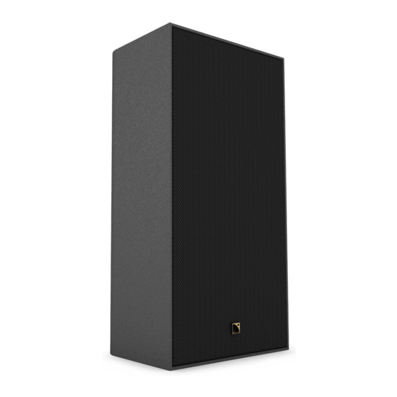
- Page 1 owner's manual (EN)
- Page 2 Document reference: X8i owner's manual (EN) version 1.0 Distribution date: April 11, 2024 © 2024 L-Acoustics. All rights reserved. No part of this publication may be reproduced or transmitted in any form or by any means without the express written consent of the publisher.
-
Page 3: Table Of Contents
Contents Safety................................6 Instructions..............................6 Introduction................................ 8 X8i................................8 How to use this manual..........................9 Revision history............................9 System components............................10 System component illustrations........................11 Electro-acoustical description..........................13 Directivity............................... 13 Preset description............................ 14 Connectors............................. 15 SPCON terminal block to speakON adapter................... 16 Rigging system description..........................17 X8i................................ - Page 4 Ceiling-mounting or truss-mounting......................127 Vertically............................ 128 Horizontally..........................145 Downward-facing........................153 Ground-mounting...........................160 Ground-mounting X8i horizontally with GROUND / GROUND55 / GROUND35......160 Pole-mounting............................165 Pole-mounting X8i with POLE......................165 Connection to LA amplied controllers......................167 Cabling schemes for X8i........................168 Cabling X8i............................169 Cabling............................
- Page 5 TILT40..............................186 GROUND.............................187 GROUND55............................188 GROUND35............................189 TILT-SUPPORT............................190 X8i-HBAR............................. 191 VBAR..............................192 CEILING-PENDANT..........................193 POLE..............................194 SPCON..............................195 APPENDIX A: Specications for screws and anchors..................196 APPENDIX B: Recommendation for speaker cables.....................197...
-
Page 6: Safety
Respect the Working Load Limit (WLL) of third party equipment. L-Acoustics is not responsible for any rigging equipment and accessories provided by third party manufacturers. Verify that the Working Load Limit (WLL) of the suspension points, chain hoists and all additional hardware rigging accessories is respected. - Page 7 Safety As a general rule, L-Acoustics recommends the use of secondary safety at all times. Be cautious when ground-stacking a loudspeaker array. Do not stack the loudspeaker array on unstable ground or surface. If the array is stacked on a structure, platform, or stage, always check that the latter can support the total weight of the array.
-
Page 8: Introduction
X8i can be driven by two presets to adapt to the acoustic needs of projects and to subwoofer coupling congurations. For strong vocal reinforcement, or when used alongside a subwoofer, the [X8i] preset boasts 129 dB of max SPL, down to 67 Hz. -
Page 9: How To Use This Manual
Introduction How to use this manual The X8i owner's manual is intended for all actors involved in the system design, implementation, preventive and corrective maintenance of the X8i system. It must be used as follows: 1. Read the technical description for an overview of all system elements, their features, and their compatibilities. -
Page 10: System Components
Refer to the LA2Xi / LA4X / LA7.16i / LA12X owner's manual for detailed instructions about the whole cabling scheme, including modulation cables and network. Rigging elements X8i-onCW On-wall or on-ceiling mounting accessory with silent blocks for X8i WALLx2 Wall-mounting kit PANx2 Adjustable pan accessory kit +/-45°... -
Page 11: System Component Illustrations
Software for remote control and monitoring of amplied controllers Refer to the Soundvision help. Refer to the LA Network Manager help. System component illustrations Cables SPCON 2 × 2.5 mm² cable custom 2-point speakON cable Rigging accessories X8i-onCW WALLx2 PANx2 X8i owner's manual (EN) version 1.0... - Page 12 System components WALL TILT TILT5 TILT15 TILT40 TILT-SUPPORT GROUND GROUND55 GROUND35 X8i-HBAR VBAR CEILING-PENDANT POLE Software applications Soundvision LA Network Manager X8i owner's manual (EN) version 1.0...
-
Page 13: Electro-Acoustical Description
1 0 0 1 0 0 0 1 0 0 0 0 Frequency (Hz) Dispersion angle diagram of a single X8i using lines of equal sound pressure at -3 dB, -6 dB, -12 dB. X8i owner's manual (EN) version 1.0... -
Page 14: Preset Description
OUT 1 IN A 0 dB 0 ms OUT 2 IN A 0 dB 0 ms OUT 3 IN A 0 dB 0 ms OUT 4 IN A 0 dB 0 ms X8i owner's manual (EN) version 1.0... -
Page 15: Connectors
Electro-acoustical description Connectors 4-point terminal block with push-in connection Internal pinout for L-Acoustics 2-way passive enclosures Terminal block points IN + IN - Transducer connectors X8i owner's manual (EN) version 1.0... -
Page 16: Spcon Terminal Block To Speakon Adapter
Electro-acoustical description SPCON terminal block to speakON adapter SPCON is a 2-point speakON to bare wire adaptor for X8i. The cables have a gauge of 2.5 mm² and the ends are equipped with ferrules. SPCON replaces the connector sealing plate. -
Page 17: Rigging System Description
Rigging system description Rigging system description X8i is a loudspeaker enclosure dedicated for installation projects. X8i can be mounted on a wall, on a ceiling, own, or secured to the ground with dedicated rigging accessories, using the inserts at the back. - Page 18 55° 0° 35° X8i includes a cable clip to run the speaker cable along the cabinet. Mount the cable clip on any available insert in the middle of the enclosure with the provided M6×20 Torx screw. 3 N.m X8i owner's manual (EN) version 1.0...
-
Page 19: Elements For Wall-Mounting
APPENDIX A: Specications for screws and anchors (p.196). TILT-SUPPORT TILT-SUPPORT is a support plate for individual X8i wall-mounting accessories. TILT-SUPPORT must be used to ensure the safety of the assembly with WALL, PAN, TILT5, TILT15, TILT40, or TILT. TILT-SUPPORT is composed of: •... -
Page 20: X8I-Oncw
Rigging system description X8i-onCW X8i-onCW is a rigging interface with silent blocks for mounting one X8i on a wall or on a ceiling. X8i-onCW is composed of: • one surface-mounting plate • three silent blocks: • one enclosure-mounting plate with two silent blocks •... -
Page 21: Wall
Rigging system description WALL WALL is a rigging interface for mounting one X8i horizontally on a wall. It must be used in combination with TILT- SUPPORT (p.19). WALL is composed of: • a main part for mounting on X8i • a rectangular washer •... -
Page 22: Wallx2
Rigging system description WALLx2 WALLx2 is a rigging interface for mounting one X8i vertically on a wall. WALLx2 is composed of two WALL (p.21), without rectangular washers: • two main parts for mounting on X8i • two wall-mounting plates • fasteners for assembly and safety... -
Page 23: Elements For Ceiling-Mounting Or Truss-Mounting
(p.196). VBAR VBAR is a rigging bracket for mounting X8i vertically on the ceiling, or for ying X8i with a truss or a threaded rod in a suspended ceiling. VBAR can be combined with TILT, TILT5, TILT15, or TILT40 to adjust the site angle when mounting X8i on the ceiling. - Page 24 Rigging system description X8i site angles when own or truss-mounted with VBAR hole N angle 9° 5° 0° -4° -9° -13° -17° X8i owner's manual (EN) version 1.0...
-
Page 25: X8I-Hbar
Rigging system description X8i-HBAR X8i-HBAR is a rigging bracket for mounting X8i horizontally on the ceiling, or for ying X8i with a truss or a threaded rod in a suspended ceiling. X8i-HBAR has six Ø 10.3 mm / 0.40 in possible pickup points for site angle setting in own conguration. When mounting on the ceiling, use one pair of adjacent, coplanar holes depending on the chosen site angle. -
Page 26: Ceiling-Pendant
-35° CEILING-PENDANT CEILING-PENDANT is a rigging accessory for ying X8i in downward-facing position with a truss or a threaded rod in a suspended ceiling. The slotted hole at the top has a diameter of Ø 12 mm / 0.47 in. -
Page 27: Elements For Site Or Azimuth Angle Adjustment
APPENDIX A: Specications for screws and anchors (p.196). TILT5 / TILT15 / TILT40 TILT5, TILT15, and TILT40 are rigging interfaces for mounting one X8i vertically or horizontally with a xed site angle of 5°, 15°, or 40° respectively. They must be used in combination with TILT-SUPPORT (p.19) or... -
Page 28: Tilt
×2 rectangular washer M6×25 Torx M5 tapered spacer TILT TILT is a rigging interface for mounting X8i vertically or horizontally with an adjustable site angle. It must be used in combination with TILT-SUPPORT (p.19) or VBAR (p.23). Optionally, TILT can be combined with (p.30) to mount... - Page 29 Rigging system description -15° -30° -20° -35° -5° -25° -40° -10° enclosure wall 0° X8i owner's manual (EN) version 1.0...
-
Page 30: Pan
Rigging system description PAN is a rigging interface for mounting one X8i horizontally on a wall with adjustable azimuth angle. It must be used in combination with TILT-SUPPORT (p.19). PAN can be combined with TILT, TILT5, TILT15, or TILT40 to mount X8i horizontally or vertically with site and azimuth angle. -
Page 31: Panx2
Rigging system description PANx2 PANx2 is a rigging interface for mounting one X8i vertically on a wall with adjustable azimuth angle. It is composed of (p.30), without the fasteners for combinations with TILT accessories or horizontal congurations: • two main parts for mounting on X8i •... -
Page 32: Elements For Ground-Mounting
Elements for ground-mounting GROUND / GROUND35 / GROUND55 GROUND, GROUND35, and GROUND55 are accessories for securing X8i to the ground with a site angle of 0°, 35°, or 55° respectively. Two Ø 6.4 mm / 0.25 in holes are available for ground-mounting the enclosure. -
Page 33: Elements For Pole-Mounting
Rigging system description Elements for pole-mounting POLE POLE is a rigging accessory for mounting X8i on a Ø 35 mm (1-3/8") pole. captive screw (x2) M10 locking nut locking knob Ø 35 mm / 1-3/8" pole-mount adapter X8i owner's manual (EN) version 1.0... -
Page 34: Mechanical Safety
The deployments described in this manual achieve a safety factor of 5. Safe/maximum limit: 1 All the mechanical congurations described in this manual are destined to mount a single X8i. Risk of injury or product damage This manual describes all allowed mechanical congurations with X8i and its accessories. - Page 35 Soundvision calculations are based on usual environmental conditions. A higher safety factor is recommended with factors such as extreme high or low temperatures, strong wind, prolonged exposition to salt water, etc. Always consult a rigging specialist to adopt safety practices adapted to such a situation. X8i owner's manual (EN) version 1.0...
-
Page 36: Loudspeaker ConGurations
123 dB 129 dB X8i point source with low-frequency element Deployed as a point source with SB10i(r), Syva Sub, or KS21(i) subwoofers, X8i system is extended in the low end and the LF contour is reinforced. Gain structure X8i and SB10i(r) provide 4 dB of headroom. -
Page 37: X8I With Sb10I(R)
Reduced maximum SPL or drive capacity with LA2Xi: refer to the LA2Xi owner's manual. X8i with SB10i(r) Coupled With SB10i(r) and the [SB10_100] preset, the bandwidth of the X8i system is extended down to 27 Hz and the system contour is reinforced. The [X8i] preset is recommended for X8i in this conguration. - Page 38 Loudspeaker congurations Separated With SB10i(r) and the [SB10_60] preset, the bandwidth of the X8i is extended down to 25 Hz and the system contour is reinforced. The [X8i_40] preset is recommended for X8i in this conguration. min. 1.7 m / 5.6 ft...
-
Page 39: X8I With Syva Sub
X8i with Syva Sub Coupled With Syva Sub and the [SYVA SUB_100] preset, the bandwidth of the X8i system is extended down to 27 Hz and the system contour is reinforced. The [X8i] preset is recommended for X8i in this conguration. -
Page 40: X8I With Ks21(I)
Loudspeaker congurations X8i with KS21(i) Coupled With KS21(i) and the [KS21_100] preset, the bandwidth of the X8i system is extended down to 31 Hz and the system contour is reinforced. The [X8i] preset is recommended for X8i in this conguration. - Page 41 Loudspeaker congurations Separated With KS21(i) and the [KS21_60] preset, the bandwidth of the X8i is extended down to 29 Hz and the system contour is reinforced. The [X8i_40] preset is recommended for X8i in this conguration. min. 1.7 m / 5.6 ft...
-
Page 42: X8I Stage Monitor
59 Hz - 20 kHz Low-latency preset A low-latency preset is available for the X8i enclosure used as a monitor ([X8i_MO]). It reduces latency from 3.84 ms down to 1.18 ms (LA7.16i) and 0.84 ms (LA2Xi / LA4X / LA12X). To combine the monitor with a subwoofer: •... -
Page 43: Rigging Procedures
Use the following tables to choose the appropriate mechanical conguration based on the deployment parameters. Each conguration links to the corresponding procedure. Risk of injury or product damage This manual describes all allowed mechanical congurations with X8i and its accessories. Do not attempt to use these products outside of their intended use. Deployment parameter denitions Site angle ("tilt"): Physical deployment parameter that refers to the position of the source as the elevation angle... - Page 44 0° to -40° VBAR (p.128) VBAR + TILT5 VBAR + TILT15 VBAR + TILT40 VBAR + TILT (p.140) (p.135) (p.135) (p.135) X8i ceiling-mounted horizontally site angle 0° to -35° 90° (downward-facing) X8i-HBAR (p.145) X8i-onCW (p.153) X8i owner's manual (EN) version 1.0...
- Page 45 Rigging procedures X8i truss-mounted or suspended by a threaded rod orientation site angle 9° to -17° 90° (downward-facing) Vertical VBAR (p.128) CEILING-PENDANT (p.158) 9° to -40° Horizontal X8i-HBAR (p.145) X8i ground-stacked orientation site angle 0° 35° 55° ‒ Vertical no rigging accessory...
-
Page 46: Wall-Mounting
TILT15 (p.57) TILT40 (p.57) TILT (p.62) WALLx2 (p.52) TILT-SUPPORT + PAN TILT-SUPPORT + PAN TILT-SUPPORT + PAN TILT-SUPPORT + PAN + TILT5 (p.73) + TILT15 (p.73) + TILT40 (p.73) + TILT (p.81) PANx2 (p.68) X8i owner's manual (EN) version 1.0... - Page 47 M6×3 spacer at M6 washer Assembly About this task For this conguration, the speaker cable must be run inside the wall or ceiling. Prerequisite Place X8i on its front face on a clean at surface. X8i owner's manual (EN) version 1.0...
- Page 48 Rigging procedures Make sure that the X8i-onCW safety screws are present and loosened. Procedure Make sure to leave enough space between the walls and the sides of the rigging element to access the screw(s) when the enclosure is mounted. 1. Drill holes in the wall for the anchors and for the cable exit(s).
- Page 49 Connect the cable to the X8i terminal block. Refer to Cabling X8i (p.169). d) Secure the enclosure-mounting plate and the connector sealing plate to X8i. Use the two M6×20 Torx screws. 5 N.m X8i owner's manual (EN) version 1.0...
- Page 50 Rigging procedures 5. Secure the bottom silent block to X8i: a) Remove the placeholder screw at the bottom of X8i. b) Secure the silent block and the M6×3 spacer at the bottom of the enclosure. Use the M6×30 Torx screw.
- Page 51 Rigging procedures 7. Tighten the safety screws on both sides and make sure the assembly is stable. 3 N.m X8i owner's manual (EN) version 1.0...
- Page 52 (daN) (daN) wall-mounting WALLx2 Ø 5.2 mm / maximum 0.20 in screw head size: Ø 11 mm / 0.43 in SPCON cannot be used in this conguration. Screws and fasteners from WALLx2 ×4 ×4 M6×25 Torx M5 tapered spacer X8i owner's manual (EN) version 1.0...
- Page 53 About this task For this conguration, the speaker cable must be run inside the wall. Prerequisite Place X8i on its front face on a clean at surface. Make sure that the WALLx2 safety screws are present and loosened. Procedure Make sure to leave enough space between the walls and the sides of the rigging element to access the screw(s) when the enclosure is mounted.
- Page 54 Remove the connector sealing plate (if present) or the placeholder screws. b) Run the cable through the WALLx2 part and through the connector sealing plate. c) Connect the speaker cable to the X8i terminal block. Refer to Cabling X8i (p.169).
- Page 55 Rigging procedures 5. Secure the bottom WALLx2 part to X8i: a) Remove the two bottom placeholder screws. b) Secure the WALLx2 part to X8i. Use two M6×25 Torx screws. 5 N.m 6. Mount X8i on the wall-mounting plates: a) Align the midpoints of the WALLx2 rear cutouts with the tapered spacers.
- Page 56 Rigging procedures 7. Tighten the two safety screws and make sure the assembly is stable. 3 N.m X8i owner's manual (EN) version 1.0...
- Page 57 Do not use TILT, TILT5, TILT15, or TILT40 upside-down. These rigging accessories are designed for negative site angles only. Screws and fasteners from TILT-SUPPORT ×2 M5 hex locknut from TILT5/TILT15/TILT40 ×2 ×2 M6×25 Torx M5 tapered spacer X8i owner's manual (EN) version 1.0...
- Page 58 About this task In this procedure, TILTxx designates the xed angle accessories TILT5, TILT15, and TILT40. Prerequisite Place X8i on its front face on a clean at surface. Make sure that the TILTxx safety screw is present and loosened. Procedure Make sure to leave enough space between the walls and the sides of the rigging element to access the screw(s) when the enclosure is mounted.
- Page 59 The wall-mounting plate gasket is facing away from TILT-SUPPORT. 3 N.m 8 mm 3. Secure TILT-SUPPORT and the wall-mounting plate to the wall. 4. Remove the two placeholder screws at the bottom of X8i. X8i owner's manual (EN) version 1.0...
- Page 60 6. Prepare the cabling. Refer to Cabling X8i (p.169). 7. Mount X8i on the wall-mounting plate: a) Align the midpoints of the TILTxx rear cutouts with the tapered spacers. b) Push the assembly downwards. X8i owner's manual (EN) version 1.0...
- Page 61 Rigging procedures 8. Tighten the safety screw and make sure the assembly is stable. 3 N.m X8i owner's manual (EN) version 1.0...
- Page 62 (daN) wall-mounting TILT-SUPPORT + Ø 6.4 mm / – any accessory 0.25 in (slotted) Risk of falling objects Do not use TILT, TILT5, TILT15, or TILT40 upside-down. These rigging accessories are designed for negative site angles only. X8i owner's manual (EN) version 1.0...
- Page 63 Rigging procedures Screws and fasteners from TILT-SUPPORT ×2 ×2 M5 hex locknut thick plain washer Ø 5 mm from TILT ×2 ×1 ×1 M6×25 Torx M4×16 Torx Axis with M4 Torx (pre-mounted) head (pre-mounted) X8i owner's manual (EN) version 1.0...
- Page 64 Rigging procedures Assembly Prerequisite Place X8i on its front face on a clean at surface. Procedure Make sure to leave enough space between the walls and the sides of the rigging element to access the screw(s) when the enclosure is mounted.
- Page 65 Rigging procedures 3. Assemble the TILT wall-mounting part with TILT-SUPPORT. Use the two M5 nuts and washers. 3 N.m 8 mm 4. Secure TILT-SUPPORT and TILT to the wall. X8i owner's manual (EN) version 1.0...
- Page 66 Rigging procedures 5. Secure TILT to X8i: a) Remove the two placeholder screws at the bottom of X8i. b) Secure the TILT enclosure-mounting part to X8i. Use the two M6×25 Torx screws. 5 N.m 6. Prepare the cabling. Refer to Cabling X8i (p.169).
- Page 67 -30° -20° -35° -5° -25° -40° -10° enclosure wall 0° c) Drive the axis through the holes and secure it with the M4×16 Torx screw. Make sure that the assembly is stable. 3 N.m X8i owner's manual (EN) version 1.0...
- Page 68 Do not use PAN or PANx2 upside-down. Do not swap the wall-mounting part(s) and the enclosure-mounting part(s). SPCON cannot be used in this conguration. Screws and fasteners from PANx2 ×2 ×4 M8×16 Torx M6×20 Torx X8i owner's manual (EN) version 1.0...
- Page 69 About this task For this conguration, the speaker cable must be run inside the wall. Prerequisite Place X8i on its front face on a clean at surface. Procedure 1. Drill holes in the wall for the anchors and for the cable exit.
- Page 70 Run the cable through the PANx2 part and through the connector sealing plate. c) Connect the cable to the X8i terminal block. Refer to Cabling X8i (p.169). d) Secure the PANx2 part and the connector sealing plate to X8i. Use two M6×20 Torx screws. 5 N.m X8i owner's manual (EN) version 1.0...
- Page 71 Rigging procedures 5. Secure the bottom PANx2 part to X8i: a) Remove the two bottom placeholder screws. b) Secure the PANx2 part to X8i. Use two M6×20 Torx screws. 5 N.m 6. Mount the assembly on the wall-mounting parts: a) Align the pins with the top holes and push the assembly downwards.
- Page 72 Rigging procedures 7. Rotate X8i to adjust the azimuth angle from -45° to +45°. - 45° + 45° 8. Tighten the two M8×16 Torx screws. Apply a torque of 10 N.m. Make sure the assembly is stable. 10 N.m X8i owner's manual (EN) version 1.0...
- Page 73 Rigging procedures Wall-mounting X8i vertically with PAN and TILT5/TILT15/TILT40 Type of deployment wall-mounting Rigging accessories TILT-SUPPORT TILT5/TILT15/TILT40 Additional material 3 compatible screws and anchors Tools torque screwdriver T25 Torx bit T30 Torx bit T40 Torx bit 8 mm wrench or 8 mm hex socket Min.
- Page 74 Ø 5 mm from PAN ×2 ×2 ×2 ×2 M5×20 Torx M5 hex locknut thick plain washer M8×16 Torx Ø 5 mm from TILT5/TILT15/TILT40 ×2 ×2 M6×25 Torx M5 tapered spacer X8i owner's manual (EN) version 1.0...
- Page 75 About this task In this procedure, TILTxx designates the xed angle accessories TILT5, TILT15, and TILT40. Prerequisite Place X8i on its front face on a clean at surface. Make sure that the TILTxx safety screw is present and loosened. Procedure Make sure to leave enough space between the walls and the sides of the rigging element to access the screw(s) when the enclosure is mounted.
- Page 76 Rigging procedures 2. Assemble the PAN wall-mounting part with TILT-SUPPORT. Use the two M5 nuts and washers. 3 N.m 8 mm 3. Secure TILT-SUPPORT and PAN to the wall. X8i owner's manual (EN) version 1.0...
- Page 77 Rigging procedures 4. Secure TILTxx to X8i: a) Remove the two placeholder screws at the bottom of X8i. b) Secure TILTxx to X8i. Use the two M6×25 Torx screws. If the shank of the screwdriver collides with TILT40, use a screwdriver extension or an angled screwdriver to drive the screws.
- Page 78 Align the tapered spacers with the midpoints of the TILTxx rear cutouts. b) Push PAN towards the top of TILTxx. 7. Tighten the safety screw on TILTxx. 3 N.m 8. Prepare the cabling. Refer to Cabling X8i (p.169). X8i owner's manual (EN) version 1.0...
- Page 79 Rigging procedures 9. Mount X8i on the PAN wall-mounting part: a) Align the pin with the top hole and push the assembly downwards. b) Drive the M8×16 Torx screw from underneath PAN. Do not fully tighten the screw. 10. Rotate the assembly to adjust the azimuth angle from -45° to +45°.
- Page 80 Rigging procedures 11. Tighten the M8×16 Torx screw. Apply a torque of 10 N.m. Make sure the assembly is stable. 10 N.m X8i owner's manual (EN) version 1.0...
- Page 81 Rigging procedures Wall-mounting X8i vertically with PAN and TILT Type of deployment wall-mounting Rigging accessories TILT-SUPPORT TILT Additional material 3 compatible screws and anchors Tools torque screwdriver T20 Torx bit T30 Torx bit T40 Torx bit T20 screwdriver 8 mm wrench or 8 mm hex socket 10 mm wrench or 10 mm hex socket Min.
- Page 82 PAN ×2 ×2 ×2 ×2 M8×16 Torx M6×25 Torx M6 hex lock nut at washer Ø 6 mm from TILT ×2 ×1 ×1 M6×25 Torx M4×16 Torx Axis with M4 Torx (pre-mounted) head (pre-mounted) X8i owner's manual (EN) version 1.0...
- Page 83 Rigging procedures Assembly Prerequisite Place X8i on its front face on a clean at surface. Procedure Make sure to leave enough space between the walls and the sides of the rigging element to access the screw(s) when the enclosure is mounted.
- Page 84 3. Secure TILT-SUPPORT and PAN to the wall. 4. Disassemble the two TILT parts. 5. Secure TILT to X8i: a) Remove the two placeholder screws at the bottom of X8i. b) Secure the TILT enclosure-mounting part to X8i. Use the two M6×25 Torx screws.
- Page 85 Use the two M6×25 Torx screws, M6 nuts and washers. 5 N.m 10 mm 7. Secure the PAN and TILT assembly to X8i: a) Assemble the two TILT parts by tting the indexing studs into the hooks. Make sure the studs are pushed all the way into the hooks.
- Page 86 -35° -5° -25° -40° -10° enclosure wall 0° c) Drive the axis through the holes and secure it with the M4×16 Torx screw. 3 N.m 8. Prepare the cabling. Refer to Cabling X8i (p.169). X8i owner's manual (EN) version 1.0...
- Page 87 Align the pin with the top hole and push the assembly downwards. b) Drive the M8×16 Torx screw from underneath the PAN. Do not fully tighten the screw. 10. Rotate X8i to adjust the azimuth angle from -45° to +45°. - 45° + 45°...
- Page 88 Rigging procedures 11. Tighten the M8×16 Torx screw. Apply a torque of 10 N.m. Make sure the assembly is stable. 10 N.m X8i owner's manual (EN) version 1.0...
-
Page 89: Horizontally
(p.95) TILT15 (p.95) TILT40 (p.95) TILT (p.100) TILT-SUPPORT + TILT-SUPPORT + PAN TILT-SUPPORT + PAN TILT-SUPPORT + PAN TILT-SUPPORT + PAN (p.107) + TILT5 (p.112) + TILT15 (p.112) + TILT40 (p.112) + TILT (p.120) X8i owner's manual (EN) version 1.0... - Page 90 Ø 6.4 mm / – any accessory 0.25 in (slotted) Screws and fasteners from TILT-SUPPORT ×2 ×2 M5 hex locknut thick plain washer Ø 5 mm from WALL ×2 ×2 ×1 M6×25 Torx M5 tapered spacer rectangular washer X8i owner's manual (EN) version 1.0...
- Page 91 Rigging procedures Assembly Prerequisite Place X8i on its front face on a clean at surface. Make sure that the WALL safety screw is present and loosened. Procedure Make sure to leave enough space between the walls and the sides of the rigging element to access the screw(s) when the enclosure is mounted.
- Page 92 The wall-mounting plate gasket is facing away from TILT-SUPPORT. 3 N.m 8 mm 3. Secure TILT-SUPPORT and the wall-mounting plate to the wall. 4. Remove the two placeholder screws in the middle of X8i. X8i owner's manual (EN) version 1.0...
- Page 93 X8i, respectively. Make sure that the safety screw is at the top when the enclosure is mounted in its nal position. 5 N.m 7. Prepare the cabling. Refer to Cabling X8i (p.169). X8i owner's manual (EN) version 1.0...
- Page 94 8. Mount the assembly on the wall-mounting plate: a) Align the midpoints of the WALL rear cutouts with the tapered spacers. b) Push the assembly downwards. 9. Tighten the safety screw and make sure the assembly is stable. 3 N.m X8i owner's manual (EN) version 1.0...
- Page 95 Do not use TILT, TILT5, TILT15, or TILT40 upside-down. These rigging accessories are designed for negative site angles only. Screws and fasteners from TILT-SUPPORT ×2 M5 hex locknut from TILT5/TILT15/TILT40 ×1 ×2 ×2 rectangular washer M6×25 Torx M5 tapered spacer X8i owner's manual (EN) version 1.0...
- Page 96 About this task In this procedure, TILTxx designates the xed angle accessories TILT5, TILT15, and TILT40. Prerequisite Place X8i on its front face on a clean at surface. Make sure that the TILTxx safety screw is present and loosened. Procedure Make sure to leave enough space between the walls and the sides of the rigging element to access the screw(s) when the enclosure is mounted.
- Page 97 The wall-mounting plate gasket is facing away from TILT-SUPPORT. 3 N.m 8 mm 3. Secure TILT-SUPPORT and the wall-mounting plate to the wall. 4. Remove the two placeholder screws in the middle of X8i. X8i owner's manual (EN) version 1.0...
- Page 98 Make sure that the safety screw is at the top when the enclosure is mounted in its nal position. If the shank of the screwdriver collides with TILT40, use a screwdriver extension or an angled screwdriver to drive the screws. 5 N.m 7. Prepare the cabling. Refer to Cabling X8i (p.169). X8i owner's manual (EN) version 1.0...
- Page 99 8. Mount the assembly on the wall-mounting plate: a) Align the TILTxx holes with the tapered spacers. b) Push the assembly downwards. 9. Tighten the safety screw. Make sure the assembly is stable. 3 N.m X8i owner's manual (EN) version 1.0...
- Page 100 (daN) wall-mounting TILT-SUPPORT + Ø 6.4 mm / – any accessory 0.25 in (slotted) Risk of falling objects Do not use TILT, TILT5, TILT15, or TILT40 upside-down. These rigging accessories are designed for negative site angles only. X8i owner's manual (EN) version 1.0...
- Page 101 Screws and fasteners from TILT-SUPPORT ×2 ×2 M5 hex locknut thick plain washer Ø 5 mm from TILT ×1 ×2 ×1 ×1 rectangular washer M6×25 Torx M4×16 Torx Axis with M4 Torx (pre-mounted) head (pre-mounted) X8i owner's manual (EN) version 1.0...
- Page 102 Assembly About this task Prerequisite Place X8i on its front face on a clean at surface. Procedure Make sure to leave enough space between the walls and the sides of the rigging element to access the screw(s) when the enclosure is mounted.
- Page 103 Rigging procedures 3. Assemble the TILT wall-mounting part with TILT-SUPPORT. Use the two M5 nuts and washers. 3 N.m 8 mm 4. Secure TILT-SUPPORT and TILT to the wall. X8i owner's manual (EN) version 1.0...
- Page 104 5. Secure TILT to X8i: a) Remove the two placeholder screws in the middle of X8i. b) Secure the TILT enclosure-mounting part with the rectangular washer to X8i. Use the two M6×25 Torx screws. Align the top and the middle hole (formed by the washer) from the rigging accessory with the top and bottom hole on X8i, respectively.
- Page 105 Rigging procedures Risk of pinching ngers Hold X8i from underneath when assembling the two TILT parts. 7. Mount X8i on the wall: a) Assemble the two TILT parts by tting the indexing studs into the hooks. Make sure the studs are pushed all the way into the hooks.
- Page 106 Rigging procedures c) Drive the axis through the holes and secure it with the M4×16 Torx screw. Make sure the assembly is stable. 3 N.m X8i owner's manual (EN) version 1.0...
- Page 107 (daN) (daN) wall-mounting TILT-SUPPORT + Ø 6.4 mm / – any accessory 0.25 in (slotted) Risk of falling objects Do not use PAN or PANx2 upside-down. Do not swap the wall-mounting part(s) and the enclosure-mounting part(s). X8i owner's manual (EN) version 1.0...
- Page 108 M8×16 Torx Assembly Prerequisite Place X8i on its front face on a clean at surface. Procedure Make sure to leave enough space between the walls and the sides of the rigging element to access the screw(s) when the enclosure is mounted.
- Page 109 Rigging procedures 2. Assemble the PAN wall-mounting part with TILT-SUPPORT. Use the two M5 nuts and washers. 3 N.m 8 mm 3. Secure TILT-SUPPORT and PAN to the wall. X8i owner's manual (EN) version 1.0...
- Page 110 4. Secure PAN to X8i: a) Remove the two placeholder screws in the middle of X8i. b) Secure the PAN enclosure-mounting part with the rectangular washer to X8i. Use the two M6×25 Torx screws. Make sure the rectangular washer is in the correct position.
- Page 111 Azimuth angle in horizontal orientation When X8i is mounted horizontally with PAN against a wall, an azimuth angle of +9°/-9° can be reached. Use a wedge or mount on a narrow wall to increase the azimuth angle, up to +45°/-45°.
- Page 112 Rigging procedures Wall-mounting X8i horizontally with PAN and TILT5/TILT15/TILT40 Type of deployment wall-mounting Rigging accessories TILT-SUPPORT TILT5/TILT15/TILT40 Additional material 3 compatible screws and anchors Tools torque screwdriver T25 Torx bit T30 Torx bit 8 mm wrench or 8 mm hex socket Min.
- Page 113 M5 hex locknut thick plain washer Ø 5 mm from PAN ×2 ×2 ×2 ×2 M5×20 Torx M5 hex locknut thick plain washer M8×16 Torx Ø 5 mm from TILT5/TILT15/TILT40 ×1 ×2 rectangular washer M6×25 Torx X8i owner's manual (EN) version 1.0...
- Page 114 About this task In this procedure, TILTxx designates the xed angle accessories TILT5, TILT15, and TILT40. Prerequisite Place X8i on its front face on a clean at surface. Make sure that the TILTxx safety screw is present and loosened. Procedure Make sure to leave enough space between the walls and the sides of the rigging element to access the screw(s) when the enclosure is mounted.
- Page 115 2. Assemble the PAN wall-mounting part with TILT-SUPPORT. Use the two M5 nuts and washers. 3 N.m 8 mm 3. Secure TILT-SUPPORT and PAN to the wall. 4. Remove the two placeholder screws in the middle of X8i. X8i owner's manual (EN) version 1.0...
- Page 116 Make sure that the safety screw is at the top when the enclosure is mounted in its nal position. If the shank of the screwdriver collides with TILT40, use a screwdriver extension or an angled screwdriver to drive the screws. 5 N.m X8i owner's manual (EN) version 1.0...
- Page 117 Align the tapered spacers with the midpoints of the TILTxx rear cutouts. b) Push PAN towards the top of TILTxx. 9. Tighten the safety screw on TILTxx. 3 N.m 10. Prepare the cabling. Refer to Cabling X8i (p.169). X8i owner's manual (EN) version 1.0...
- Page 118 Azimuth angle in horizontal orientation When X8i is mounted horizontally with PAN against a wall, an azimuth angle of +9°/-9° can be reached. Use a wedge or mount on a narrow wall to increase the azimuth angle, up to +45°/-45°.
- Page 119 Rigging procedures 13. Tighten the M8 screw. Apply a torque of 10 N.m. Make sure the assembly is stable. 10 N.m X8i owner's manual (EN) version 1.0...
- Page 120 Rigging procedures Wall-mounting X8i horizontally with PAN and TILT Type of deployment wall-mounting Rigging accessories TILT-SUPPORT TILT Additional material 3 compatible screws and anchors Tools torque screwdriver T20 Torx bit T30 Torx bit T40 Torx bit T20 screwdriver 8 mm wrench or 8 mm hex socket 10 mm wrench or 10 mm hex socket Min.
- Page 121 ×2 ×2 ×2 M8×16 Torx M6×25 Torx M6 hex lock nut at washer Ø 6 mm from TILT ×1 ×2 ×1 ×1 rectangular washer M6×25 Torx M4×16 Torx Axis with M4 Torx (pre-mounted) head (pre-mounted) X8i owner's manual (EN) version 1.0...
- Page 122 Rigging procedures Assembly Prerequisite Place X8i on its front face on a clean at surface. Procedure Make sure to leave enough space between the walls and the sides of the rigging element to access the screw(s) when the enclosure is mounted.
- Page 123 4. Secure TILT to X8i: a) Remove the two placeholder screws in the middle of X8i. b) Secure the TILT enclosure-mounting part with the rectangular washer to X8i. Use the two M6×25 Torx screws. Align the top and the middle hole (formed by the washer) from the rigging accessory with the top and bottom hole on X8i, respectively.
- Page 124 Use the two M6×25 Torx screws, M6 nuts and washers. 5 N.m 10 mm 6. Secure the PAN and TILT assembly to X8i: a) Assemble the two TILT parts by tting the indexing studs into the hooks. Make sure the studs are pushed all the way into the hooks.
- Page 125 8. Mount the assembly on the PAN wall-mounting part: a) Align the pin with the top hole and push the assembly downwards. b) Drive the M8×16 Torx screw from underneath the PAN. Do not fully tighten the screw. X8i owner's manual (EN) version 1.0...
- Page 126 Azimuth angle in horizontal orientation When X8i is mounted horizontally with PAN against a wall, an azimuth angle of +9°/-9° can be reached. Use a wedge or mount on a narrow wall to increase the azimuth angle, up to +45°/-45°.
-
Page 127: Ceiling-Mounting Or Truss-Mounting
(p.135) (p.135) X8i ceiling-mounted horizontally site angle 0° to -35° 90° (downward-facing) X8i-HBAR (p.145) X8i-onCW (p.153) X8i truss-mounted or suspended by a threaded rod orientation site angle 9° to -17° 90° (downward-facing) Vertical VBAR (p.128) CEILING-PENDANT (p.158) 9° to -40°... -
Page 128: Vertically
Rigging procedures Vertically Ceiling-mounting or ying X8i vertically with VBAR Type of deployment ceiling-mounting or truss-mounting Rigging accessories VBAR Additional material 2 compatible screws and anchors, or 1 max. Ø10 mm / 0.39 in truss clamp, or 1 max. Ø10 mm / 0.39 in threaded rod, with corresponding nuts and... - Page 129 About this task For this conguration, the speaker cable must be run inside the ceiling. Prerequisite Place X8i on its front face on a clean at surface. Procedure Ceiling-mounting holes When ceiling-mounting with VBAR, always use holes 1 and 7 (at both ends) to ensure optimal support.
- Page 130 3. Run the speaker cable through VBAR. 4. Prepare X8i cabling: a) Remove the connector sealing plate. b) Run the cable through the connector sealing plate. c) Connect the cable to the X8i terminal block. Refer to Cabling X8i (p.169). X8i owner's manual (EN) version 1.0...
- Page 131 Rigging procedures Risk of crushing injury This step requires two operators. 5. Hold the connector sealing plate against the connector and secure X8i to VBAR. Use two M6×25 Torx screws. Make sure the assembly is stable. 5 N.m X8i owner's manual (EN) version 1.0...
- Page 132 Rigging procedures Flying X8i with VBAR About this task holes for cable passage ceiling-mounting X8i site angles when own or truss-mounted with VBAR hole N angle 9° 5° 0° -4° -9° -13° -17° Procedure 1. Run the speaker cable through VBAR.
- Page 133 2. Prepare X8i cabling: a) Remove the connector sealing plate. b) Run the cable through the connector sealing plate. c) Connect the cable to the X8i terminal block. Refer to Cabling X8i (p.169). 3. Hold the connector plate and position X8i upright.
- Page 134 Risk of crushing injury This step requires two operators. 5. Choose the pickup point and y X8i with a truss clamp or a threaded rod (maximum Ø10 mm / 0.39 in). Make sure the assembly is stable. X8i owner's manual (EN) version 1.0...
- Page 135 Rigging procedures Ceiling-mounting X8i vertically with VBAR and TILT5/TILT15/TILT40 Type of deployment ceiling-mounting Rigging accessories VBAR TILT5/TILT15/TILT40 Additional material 2 compatible screws and anchors Tools torque screwdriver T25 Torx bit T30 Torx bit 8 mm wrench or 8 mm hex socket Min.
- Page 136 In this procedure, TILTxx designates the xed angle accessories TILT5, TILT15, and TILT40. Prerequisite Place X8i on its front face on a clean at surface. Make sure that the TILTxx safety screw is present and loosened. X8i owner's manual (EN) version 1.0...
- Page 137 Use two M5×20 Torx, two M5 washers, and two M5 nuts. The wall-mounting plate gasket is facing away from VBAR. 3 N.m 8 mm 3. Secure VBAR and the wall-mounting plate to the ceiling. X8i owner's manual (EN) version 1.0...
- Page 138 5. Secure TILTxx to X8i: a) Remove the connector sealing plate (if present) or the placeholder screws. b) Run the cable through TILTxx and through the connector sealing plate. c) Connect the speaker cable to the X8i terminal block. Refer to Cabling X8i (p.169).
- Page 139 6. Mount X8i on VBAR: a) Align the midpoints of the TILTxx rear cutouts with the tapered spacers. b) Push the assembly downwards. 7. Tighten the safety screw and make sure the assembly is stable. 3 N.m X8i owner's manual (EN) version 1.0...
- Page 140 Rigging procedures Ceiling-mounting X8i vertically with VBAR and TILT Type of deployment ceiling-mounting Rigging accessories VBAR TILT Additional material 2 compatible screws and anchors Tools torque screwdriver T20 Torx bit T30 Torx bit T40 Torx bit T20 screwdriver 10 mm wrench or 10 mm hex socket Min.
- Page 141 Axis with M4 Torx (pre-mounted) head (pre-mounted) Assembly About this task In this procedure, TILTxx designates the xed angle accessories TILT5, TILT15, and TILT40. Prerequisite Place X8i on its front face on a clean at surface. X8i owner's manual (EN) version 1.0...
- Page 142 Ø 10.4 mm / 0.4 in 2. Assemble the TILT wall-mounting part with VBAR. Use two M6×25 Torx, two M6 nuts and two M6 washers. 3 N.m 10 mm 3. Secure VBAR to the ceiling. X8i owner's manual (EN) version 1.0...
- Page 143 Connect the speaker cable to the X8i terminal block. Refer to Cabling X8i (p.169). d) Secure the TILT enclosure-mounting part and the connector sealing plate to X8i. Use the two M6×25 Torx screws. 5 N.m Risk of crushing injury This step requires two operators.
- Page 144 -30° -20° -35° -5° -25° -40° -10° enclosure wall 0° c) Drive the axis through the holes and secure it with the M4×16 Torx screw. Make sure that the assembly is stable. 3 N.m X8i owner's manual (EN) version 1.0...
-
Page 145: Horizontally
Rigging procedures Horizontally Ceiling-mounting or truss-mounting X8i horizontally with X8i-HBAR Type of deployment ceiling-mounting or truss-mounting Rigging accessories X8i-HBAR Additional material 2 compatible screws and anchors, or 1 max. Ø10 mm / 0.39 in truss clamp, or 1 max. Ø10 mm / 0.39 in threaded rod, with corresponding nuts and... - Page 146 X8i site angles when ceiling-mounted with X8i-HBAR holes N angle 1 + 2 0° 3 + 4 -14° 5 + 6 -35° Prerequisite Place X8i on its front face on a clean at surface. X8i owner's manual (EN) version 1.0...
- Page 147 Rigging procedures Procedure Ceiling-mounting holes When ceiling-mounting with X8i-HBAR, use one pair of adjacent, coplanar holes depending on the chosen site angle. 1. Drill holes in the ceiling for X8i-HBAR. 6 x Ø 11 mm / 0.43 in 2. Secure X8i-HBAR to the ceiling.
- Page 148 Rigging procedures 3. Remove the three placeholder screws in the middle of X8i. X8i-HBAR can be mounted on a horizontal X8i turned either way: with the connector plate on the right-hand side with the connector plate on the left-hand side Risk of crushing injury This step requires two operators.
- Page 149 Rigging procedures 5 N.m 6. Prepare X8i cabling. Refer to Cabling X8i (p.169). X8i owner's manual (EN) version 1.0...
- Page 150 Flying X8i with X8i-HBAR About this task X8i site angles when own or truss-mounted with X8i-HBAR hole N angle 9° 1° -10° -20° -30° -40° Prerequisite Place X8i on its front face on a clean at surface. X8i owner's manual (EN) version 1.0...
- Page 151 Rigging procedures Procedure 1. Remove the three placeholder screws in the middle of X8i. X8i-HBAR can be mounted on a horizontal X8i turned either way: with the connector plate on the right-hand side with the connector plate on the left-hand side Do not fully tighten the screws.
- Page 152 Rigging procedures 3. Choose the pickup point and y X8i with a truss clamp or a threaded rod (maximum Ø 10 mm / 0.39 in). Make sure the assembly is stable. 4. Adjust the roll angle. 5. Place X8i on its front face and tighten the screws.
-
Page 153: Downward-Facing
0.25 in with washers: 13.10 mm / 0.51 in SPCON cannot be used in this conguration. Screws and fasteners from X8i-onCW ×1 ×2 ×4 ×1 ×4 M6×35 Torx M6×20 Torx M6×10 spacer M6×3 spacer at M6 washer X8i owner's manual (EN) version 1.0... - Page 154 About this task For this conguration, the speaker cable must be run inside the wall or ceiling. Prerequisite Place X8i on its front face on a clean at surface. Make sure that the X8i-onCW safety screws are present and loosened. Procedure Make sure to leave enough space between the walls and the sides of the rigging element to access the screw(s) when the enclosure is mounted.
- Page 155 Connect the cable to the X8i terminal block. Refer to Cabling X8i (p.169). d) Secure the enclosure-mounting plate and the connector sealing plate to X8i. Use the two M6×20 Torx screws. 5 N.m X8i owner's manual (EN) version 1.0...
- Page 156 Rigging procedures 5. Secure the bottom silent block to X8i: a) Remove the placeholder screw at the bottom of X8i. b) Secure the silent block and the M6×3 spacer at the bottom of the enclosure. Use the M6×30 Torx screw.
- Page 157 Rigging procedures 7. Tighten the safety screws on both sides and make sure the assembly is stable. 3 N.m X8i owner's manual (EN) version 1.0...
- Page 158 Screws and fasteners from CEILING-PENDANT ×2 M6×20 Torx Assembly About this task For this conguration, the speaker cable must be run inside the ceiling. Prerequisite Place X8i on its front face on a clean at surface. X8i owner's manual (EN) version 1.0...
- Page 159 2. Secure CEILING-PENDANT to X8i. Use two M6×25 Torx screws. 5 N.m 3. Fly X8i with a truss clamp or a threaded rod (maximum Ø 12 mm / 0.47 in). Make sure the assembly is stable. 4. Prepare the cabling. Refer to Cabling X8i (p.169).
-
Page 160: Ground-Mounting
Horizontal GROUND (p.160) GROUND35 (p.160) GROUND55 (p.160) Ground-mounting X8i horizontally with GROUND / GROUND55 / GROUND35 Type of deployment ground-stacking Rigging accessories GROUND / GROUND55 / GROUND35 Additional material 2 compatible screws and anchors Tools torque screwdriver... - Page 161 • For GROUND35 (35° site angle) : with the connector plate on the left. • For GROUND (0° site angle): turned either way. Procedure 1. Remove one placeholder screw for GROUND or two for GROUND55/GROUND35, in the middle of X8i. GROUND GROUND55/GROUND35...
- Page 162 Use one M6×25 Torx screw (GROUND) or two M6×25 Torx screws (GROUND55/GROUND35). GROUND55 GROUND35 GROUND 3. Place X8i in monitor position, with GROUNDxx resting on the ground. Make sure that GROUNDxx is aligned with the cabinet. Make adjustments if necessary. GROUND55 GROUND35 GROUND X8i owner's manual (EN) version 1.0...
- Page 163 GROUND55 GROUND35 5 N.m GROUND 5. Place X8i at its nal location and secure GROUNDxx to the ground. Make sure the assembly is stable. 27 mm / 1.1 in 27 mm / 1.1 in Ø 6.4 mm / 0.24 in Ø...
- Page 164 Rigging procedures 27 mm / 1.1 in Ø 6.4 mm / 0.24 in GROUND X8i owner's manual (EN) version 1.0...
-
Page 165: Pole-Mounting
Ø 35 mm (1-3/8") pole Tools torque screwdriver screwdriver extension T30 Torx bit 17 mm wrench Min. number of operators Assembly Procedure 1. Remove the two placeholder screws in the middle or at the bottom of X8i. X8i owner's manual (EN) version 1.0... - Page 166 Rigging procedures 2. Secure POLE to X8i with the two captive screws. Use a screwdriver extension. 5 N.m 3. Mount the assembly on a Ø 35 mm (1-3/8") pole. Use a screwdriver extension. 4. Tighten the locking knob and the nut.
-
Page 167: Connection To La AmpliEd Controllers
Power Budget values, otherwise the Fuse Protect algorithm may be triggered. When powered by a 100 V power supply, reduce the number of enclosures in order not to exceed 75% of the power gauge. X8i owner's manual (EN) version 1.0... -
Page 168: Cabling Schemes For X8I
1− 2− Terminal block output (LA2Xi BTL) 2.5 mm² cables 1− 2− One-channel speakON output custom cable 2.5 mm² cable 1+/1- Two-channel speakON output custom cable 2.5 mm² cable 1+/1- 2+/2- 2.5 mm² cable X8i owner's manual (EN) version 1.0... -
Page 169: Cabling X8I
14 AWG / 2.5 mm² Maximum electric current 30 A Maximum electrical rating 105 °C (221 °F) / 600 V Terminal material tin-plated copper Dimensions 12 mm / 0.47 in 2.5 mm / 0.10 in X8i owner's manual (EN) version 1.0... -
Page 170: Cabling
Procedure 1. Remove the connector sealing plate (if present) or the placeholder screws. 2. Insert the cable through the cable gland. X8i owner's manual (EN) version 1.0... - Page 171 5. Push the wires into the terminals. If necessary, use a small tool in the hole next to the terminal to unlock it. 6. Secure the connector sealing plate to the enclosure. Apply a torque of 3 N.m. 3 N.m X8i owner's manual (EN) version 1.0...
- Page 172 Connection to LA amplied controllers What to do next To remove the cables, use the small tool to unlock the terminals and pull on the wires. X8i owner's manual (EN) version 1.0...
-
Page 173: Cabling With Spcon
SPCON is not compatible with the following rigging accessories: • X8i-onCW • WALLx2 • PANx2 • GROUND55 • GROUND35 • GROUND Procedure 1. Remove the connector sealing plate (if present) or the placeholder screws. X8i owner's manual (EN) version 1.0... - Page 174 2. Push the SPCON ferrules into the terminals. If necessary, use a small tool in the hole next to the terminal to unlock it. 3. Secure SPCON to X8i. Use the two provided M6×25 Torx screws. 3 N.m X8i owner's manual (EN) version 1.0...
- Page 175 Connection to LA amplied controllers 4. Connect the speaker cable to SPCON. X8i owner's manual (EN) version 1.0...
-
Page 176: SpeciCations
RAL code on special order IP55 Peak level measured at 1 m under free eld conditions using pink noise with crest factor 4 (preset specied in brackets). With connector at the top and connector sealing plate. X8i owner's manual (EN) version 1.0... - Page 177 Specications X8i dimensions 240 mm / 9.4 in 217 mm / 8.5 in X8i owner's manual (EN) version 1.0...
-
Page 178: X8I-Oncw
Specications X8i-onCW specications Description On-wall or on-ceiling mounting accessory with silent blocks for X8i Weight (net) 0.7 kg / 1.5 lb Material steel with anti-corrosion coating X8i-onCW dimensions 20 mm / 0.79 in 105 mm / 4.13 in 4 x Ø 6.4 mm / 0.25 in 5 mm / 0.2 in... -
Page 179: Wall
Weight (net) 0.3 kg / 0.7 lb Material steel with anti-corrosion coating WALL dimensions 45 mm / 1.8 in 16 mm / 0.63 in 30 mm / 1.2 in 30 mm / 1.2 in X8i owner's manual (EN) version 1.0... -
Page 180: Pan
0.4 kg / 0.9 lb Material steel with anti-corrosion coating PAN dimensions 39 mm / 1.5 in 33 mm / 1.3 in 2 x Ø 6.4 mm / 0.25 in 41 mm / 1.6 in X8i owner's manual (EN) version 1.0... - Page 181 Weight (net) 0.4 kg / 0.9 lb Material steel with anti-corrosion coating WALLx2 dimensions 45 mm / 1.8 in 16 mm / 0.63 in 30 mm / 1.2 in 30 mm / 1.2 in X8i owner's manual (EN) version 1.0...
- Page 182 0.8 kg / 1.8 lb Material steel with anti-corrosion coating PANx2 dimensions 39 mm / 1.5 in 33 mm / 1.3 in 2 x Ø 6.4 mm / 0.25 in 41 mm / 1.6 in X8i owner's manual (EN) version 1.0...
-
Page 183: Tilt
1.1 kg / 2.4 lb Material steel with anti-corrosion coating TILT dimensions 47 mm / 1.9 in 45 mm / 1.7 in Ø 6.4 mm / 0.25 in 30 mm / 1.2 in 51 mm / 2 in X8i owner's manual (EN) version 1.0... - Page 184 0.3 kg / 0.7 lb Material steel with anti-corrosion coating TILT5 dimensions 45 mm / 1.8 in 30 mm / 1.2 in 30 mm / 1.2 in 20 mm / 0.8 in 30 mm / 1.2 in X8i owner's manual (EN) version 1.0...
- Page 185 0.4 kg / 0.9 lb Material steel with anti-corrosion coating TILT15 dimensions 46 mm / 1.8 in 45 mm / 1.8 in 30 mm / 1.2 in 18 mm / 0.71 in 30 mm / 1.2 in X8i owner's manual (EN) version 1.0...
- Page 186 0.5 kg / 1.1 lb Material steel with anti-corrosion coating TILT40 dimensions 45 mm / 1.8 in 84 mm / 3.3 in 30 mm / 1.2 in 14 mm / 0.55 in 30 mm / 1.2 in X8i owner's manual (EN) version 1.0...
- Page 187 GROUND specications Description Ground-mounting accessory Weight (net) 0.2 kg / 0.4 lb Material steel with anti-corrosion coating GROUND dimensions 47 mm / 1.9 in 35 mm / 1.4 in Ø 6.4 mm / 0.25 in X8i owner's manual (EN) version 1.0...
- Page 188 GROUND55 dimensions 50 mm / 1.9 in 47 mm / 1.9 in 74 mm / 2.9 in 15 mm / 0.6 in 2 X Ø 6.4 mm / 0.25 in X8i owner's manual (EN) version 1.0...
- Page 189 GROUND35 dimensions 36 mm / 1.4 in 47 mm / 1.9 in 75 mm / 3 in 15 mm / 0.6 in 2 x Ø 6.4 mm / 0.25 in X8i owner's manual (EN) version 1.0...
- Page 190 Weight (net) 0.5 kg / 1.1 lb Material steel with anti-corrosion coating TILT-SUPPORT dimensions 100 mm / 3.9 in 18 mm / 0.7 in Ø 6.6 mm / 0.26 in 5 mm / 0.19 in X8i owner's manual (EN) version 1.0...
- Page 191 0.5 kg / 1.1 lb Material steel with anti-corrosion coating X8i-HBAR dimensions 163 mm / 6.4 in 40 mm / 1.6 in 107 mm / 4.2 in 6 x Ø 11 mm / 0.43 in X8i owner's manual (EN) version 1.0...
- Page 192 0.5 kg / 1.1 lb Material steel with anti-corrosion coating VBAR dimensions 45 mm / 1.8 in 170 mm / 6.7 in Ø 9 mm / 0.35 in Ø 11 mm / 0.43 in X8i owner's manual (EN) version 1.0...
- Page 193 68 mm / 2.7 in 32 mm / 1.3 in 32 mm / 1.3 in 27 mm / 1.1 in 36 mm / 1.4 in Ø 12 mm / 0.47 in Ø 6.4 mm / 0.25 in X8i owner's manual (EN) version 1.0...
- Page 194 117 mm / 4.6 in 48 mm / 1.9 in 101 mm / 3.9 in 40 mm / 1.6 in 2 x Ø 12 mm / 0.47 in Ø 36 mm / 1.4 in X8i owner's manual (EN) version 1.0...
- Page 195 2-point speakON adaptor (2.5 mm² gauge) for terminal blocks Weight (net) 0.1 kg / 0.2 lb Material moulded ABS polymer SPCON dimensions 80 mm / 3.1 in 129 mm / 5.1 in 53 mm / 2.1 in X8i owner's manual (EN) version 1.0...
- Page 196 Specications for screws and anchors Specications for screws and anchors Use the following information to choose compatible screws and anchors for mounting X8i on the wall, on the ceiling, or on the ground. Risk of crushing injury Ensure that the wall or ceiling can support the load of the product.
- Page 197 2.7 Ω load ‒ ‒ Use the more detailed L-Acoustics calculation tool to evaluate cable length and gauge based on the type and number of loudspeakers connected. The calculation tool is available on our website: https://www.l-acoustics.com/installation-tools/ X8i owner's manual (EN) version 1.0...
- Page 198 L-Acoustics 13 rue Levacher Cintrat - 91460 Marcoussis - France +33 1 69 63 69 63 - info@l-acoustics.com www.l-acoustics.com...
Need help?
Do you have a question about the X8i and is the answer not in the manual?
Questions and answers