Table of Contents
Advertisement
Quick Links
Advertisement
Table of Contents

Related Manuals for L-Acoustics L2


Summary of Contents for L-Acoustics L2
- Page 1 owner's manual (EN)
- Page 2 Document reference: L2 owner's manual (EN) version 5.0 Distribution date: October 22, 2024 © 2024 L-Acoustics. All rights reserved. No part of this publication may be reproduced or transmitted in any form or by any means without the express written consent of the publisher.
-
Page 3: Table Of Contents
Contents Safety....................................6 Instructions................................6 Introduction..................................8 L2/L2D 16-channel active progressive curvature WST enclosures................8 How to use this manual............................9 Revision history..............................10 System components.................................11 System component illustrations..........................12 Electro-acoustical description............................15 Polar pattern................................15 Adjustable fins............................... 16 Directivity................................20 Preset description..............................23 Connectors................................24 Rigging system description.............................. 25 L2/L2D................................... - Page 4 Securing L2/L2D on L2-CHARIOT/L2D-CHARIOT....................86 Flying..................................93 Securing LA-RAK III on L2-BUMP with LA-RAKMOUNT................93 Flying an L2/L2D array with L2-BUMP and L2-BAR................. 97 Flying an L2/L2D array with L2-RIGBAR....................107 Flying an L2/L2D array with L2-SCREEN/L2D-SCREEN................ 109 Adding a pullback with L2-RIGBAR......................127 Stacking................................
- Page 5 L2-BAR................................186 L2-RIGBAR................................187 LA-RAKMOUNT..............................188 LA-SLING2T................................ 189 BPCHAIN 1.5T..............................190 K2-JACK................................191 L2-LASERMOUNT...............................192 DELTA 1.5T.................................193 L2-SCREEN.................................194 L2D-SCREEN..............................195 L2-CHARIOT................................196 L2D-CHARIOT..............................197 L2-CHARIOTLID..............................198 L2D-CHARIOTLID............................... 199 L2-BUMPFLIGHT..............................200 L2-BUMPFLIGHTADDLAYER..........................201 SC32-ROLL500 BE............................. 202 APPENDIX A: Recommendation for speaker cables....................203 APPENDIX B: Installing a laser inclinometer........................ 204 L2-LASERMOUNT...............................204...
-
Page 6: Safety
Respect the Working Load Limit (WLL) of third party equipment. L-Acoustics is not responsible for any rigging equipment and accessories provided by third party manufacturers. Verify that the Working Load Limit (WLL) of the suspension points, chain hoists and all additional hardware rigging accessories is respected. - Page 7 This system is intended for use by trained personnel for professional applications. As part of a continuous evolution of techniques and standards, L-Acoustics reserves the right to change the specifications of its products and the content of its documents without prior notice.
-
Page 8: Introduction
L-ISA deployments in mid-sized festivals and tours yet also in performing arts, musical, broadcast or corporate events, and much more. Each L2 and L2D element is composed of eight 3" compression drivers loaded on DOSC waveguides, eight 10" drivers and four 12" drivers mounted on the sides. -
Page 9: How To Use This Manual
Introduction How to use this manual The L2 owner's manual is intended for all actors involved in the system design, implementation, preventive and corrective maintenance of the L2 system. It must be used as follows: 1. Read the technical description for an overview of all system elements, their features, and their compatibilities. -
Page 10: Revision History
Jan. 2024 • Updated System components (p.11). • Updated Loudspeaker configurations (p.51). • Updated Securing LA-RAK III on L2-BUMP with LA-RAKMOUNT (p.93). • Updated the visuals of L2-RIGBAR. • Added the specifications of L2-BUMPFLIGHT (p.200) and BUMPFLIGHTADDLAYER (p.201). Jun. 2024 •... -
Page 11: System Components
Refer to the LA7.16 / LA7.16i owner's manual for detailed instructions about the whole cabling scheme, including modulation cables and network. Rigging elements L2-BUMP Flying frame for L2 and L2D (incl. 1 extension sling + 1 laser adapter) L2-BAR Extension bar for L2-BUMP L2-RIGBAR... -
Page 12: System Component Illustrations
Modular flightcase for 1 L2-BUMP and rigging elements L2-BUMPFLIGHT extension for one additional L2-BUMP BUMPFLIGHTADDLAYER L2-ROLL Lift and roll accessory for L2 and L2D (to be used with L2-RIGBAR) Screens L2-SCREEN Acoustically transparent front and side screen for L2 L2D-SCREEN... - Page 13 System components Rigging accessories L2-BUMP L2-BAR L2-RIGBAR LA-RAKMOUNT LA-SLING2T BPCHAIN K2-JACK 1.5T LASERMOUNT DELTA 1.5T Screens L2-SCREEN L2D-SCREEN L2 owner's manual (EN) version 5.0...
-
Page 14: Software Applications
System components Software applications Soundvision LA Network Manager Transportation L2-CHARIOT L2-CHARIOTCOV L2-CHARIOTLID L2D-CHARIOT L2D-CHARIOTCOV L2D-CHARIOTLID L2-BUMPFLIGHT L2-BUMPFLIGHTADDLAYER L2-ROLL L2 owner's manual (EN) version 5.0... -
Page 15: Electro-Acoustical Description
Polar pattern L2 and L2D each feature eight low frequency loudspeakers. L2 and L2D each feature four low cardioid (LC) loudspeakers on the sides, allowing a standard array to exhibit a broadband cardioid pattern that minimizes rear SPL at low frequencies. -
Page 16: Adjustable Fins
Adjustable fins Horizontal directivity can be set independently on the four Panflex modules of L2 and the top two Panflex modules of L2D using the push-push mechanism of the fins in combination with the specific electronic presets. There are four possible settings: 70°... - Page 17 Electro-acoustical description 110° setting (preset [L2 110xx] / [L2D 110xx]) 70° setting (preset [L2 70xx] / [L2D 70xx]) Setting the fins in the 70° position offers an additional 2 dB on-axis (> 2 kHz). L2 owner's manual (EN) version 5.0...
- Page 18 Electro-acoustical description 90° setting (preset [L2 90xx] / [L2D 90xx]) Setting the fins in the 90° position offers an additional 1 dB on-axis (> 2 kHz). L2 owner's manual (EN) version 5.0...
- Page 19 Electro-acoustical description Mixed setting L2 with a 70° setting on module 1 and L2D with a 110° setting on module 1 and 2, and a fixed 2, and a 110° setting on module 3 and 4 directivity pattern from 110° to 140° on module 3 and 4...
-
Page 20: Directivity
Electro-acoustical description Directivity L2 generates an enclosure directivity pattern of 10° and a waveguide directivity pattern of 70° / 110° symmetric or 90° asymmetric (-6 dB) depending on the fins settings. -100 -120 -140 -160 -180 1000 10000 Frequency (Hz) Dispersion angle diagram of one L2 with 110°... - Page 21 -120 -140 -160 -180 1000 10000 Frequency (Hz) Dispersion angle diagram of one L2 with 90° fins settings and a cardioid pattern, using lines of equal sound pressure at -3 dB, -6 dB, -12 dB. -100 -120 -140 -160 -180...
- Page 22 -100 -120 -140 -160 -180 1000 10000 Frequency (Hz) Dispersion angle diagram of one L2D at 140° with a cardioid pattern, using lines of equal sound pressure at -3 dB, -6 dB, -12 dB. L2 owner's manual (EN) version 5.0...
-
Page 23: Preset Description
Electro-acoustical description Preset description [L2 70] [L2 90] [L2 110] [L2 70_S] [L2 90_S] [L2 110_S] [L2D 70] [L2D 90] [L2D 110] [L2D 70_S] [L2D 90_S] [L2D 110_S] outputs channels routing gain delay polarity mute OUT 1 OUT 2 OUT 3... -
Page 24: Connectors
Electro-acoustical description Connectors 1 × 37-point male connector (32 points used) 1 × 37-point male connector (32 points used) Internal pinout for L-Acoustics active 16-channel enclosures connector points Transducer connectors LF1/LF2 LF3/LF4 LF5/LF6 LF7/LF8 viewed from the front m/n/p/r/s not used... -
Page 25: Rigging System Description
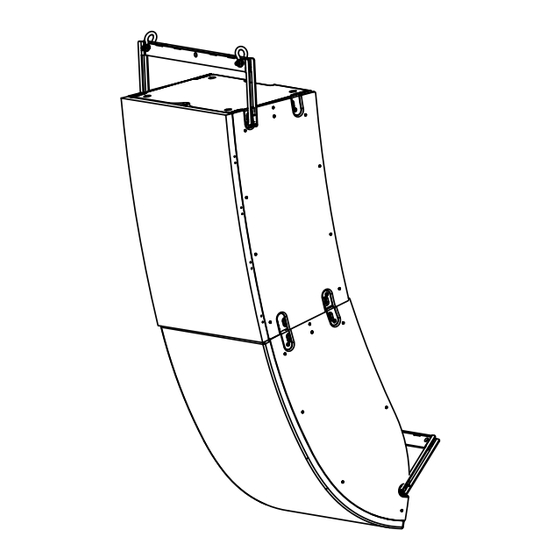
The L2 system includes two enclosures: L2 and L2D. Each enclosure can be flown or stacked alone, or assembled into a flown array. The coverage of the array is achieved by the 10° curvature of the L2 enclosures, while the 60° curvature of L2D is designed to make it the last enclosure at the bottom of the array. - Page 26 The rigging elements and latches are fitted with yellow safety labels that are visible when they are not safely locked. On both enclosures, seven inserts on each side provide further options such as flying with L2-RIGBAR as the main or pullback accessory, stacking on L2-CHARIOT/L2D-CHARIOT, securing L2-LASERMOUNT or L2-ROLL.
- Page 27 Rigging system description L2 features four ground runners on the bottom, and both L2 and L2D feature matching tracks on the top. Two ergonomic handles on each side of the enclosures are available for handling. Dedicated chariots for L2/L2D L2 is intended for use only with L-Acoustics L2-CHARIOT.
- Page 28 Rigging system description L2 and L2D feature cable clips at the rear to secure the SC32 cables. Two L2 at the top of an array One L2 and one L2D at the bottom of an array Risk of site angle modification Do not secure the SC32 cables to the rigging element.
-
Page 29: Rigging Elements
L2-BUMP is a rigging frame designed for flying L2 and L2D. L2-BUMP can be used as the main lifting accessory for flying arrays of L2 with L2D, or a single L2D using the included two Ø19 mm shackles WLL 3.25 t and extension sling. - Page 30 Front Rear To increase the site angle, four additional holes are available to add one L2-BAR on the central bar or two on each side bar. L2-BUMP is compatible with LA-RAKMOUNT to secure a single LA-RAK III above the array. Refer to LA-RAKMOUNT (p.35).
-
Page 31: L2-Bar
By adding L2-BAR to L2-BUMP, the site angle range can be increased. Seventeen holes are available on L2-BAR, which can be attached to L2-BUMP as a rear or a front extension and in position A or B, thus offering a total of 68 discrete positions for pickup points. -
Page 32: L2-Rigbar
L2-RIGBAR Secured at the bottom of the array using two ball-locking pins, L2-RIGBAR can be used as a pullback either with L2- BUMP combined with L2-BAR or another L2-RIGBAR as the main lifting accessory, to provide a lightweight solution for flying an L2 array. - Page 33 Rigging system description Secure L2-RIGBAR at the front for a positive initial site angle. Always implement a secondary safety using available holes. pickup point safety point safety points pickup points L2 owner's manual (EN) version 5.0...
-
Page 34: Delta 1.5T
Rigging system description DELTA 1.5T Combined with L2-BUMP and L2-BAR, DELTA 1.5T can be used to control the azimuth angle while L2-BAR controls the site angle. The recommended space between the two lifting points is 1 m / 3.3 ft. -
Page 35: La-Rakmount
LA-RAKMOUNT is designed to stack one LA-RAK III on top of a flown array. LA-RAKMOUNT is composed of two mounting cradles with rails. The two cradles are screwed on L2-BUMP. LA-RAKMOUNT must be used with two L2-BAR. L2 owner's manual (EN) version 5.0... -
Page 36: K2-Jack
Rigging system description K2-JACK K2-JACK is a set of two bars and four feet with screw jacks and hand wheels. K2-JACK can be fitted onto L2- CHARIOT or L2D-CHARIOT to improve stability or to correct floor discrepancies. During transportation, make sure the bolts are tightened. -
Page 37: L2-Lasermount
Rigging system description L2-LASERMOUNT L2-LASERMOUNT is designed to secure a laser inclinometer to the inserts of L2 or L2D using a knob and a ball- locking pin. L2-LASERMOUNT is installed on one side of the enclosure depending on the availability of the insert for the ball- locking pin. -
Page 38: Storage And Handling
Storage and handling L2-ROLL As L2/L2D are delivered upside down, L2-ROLL can be used with L2-RIGBAR to reverse the enclosure and secure it on its chariot. It can also be used to turn L2/L2D upside down to perform maintenance procedures. -
Page 39: L2-Chariot
Rigging system description L2-CHARIOT L2-CHARIOT is a chariot designed to transport one L2. It features four ball-locking pins to secure L2. Do not move or transport more than one L2 on L2-CHARIOT. L2-CHARIOT is intended for use only with L-Acoustics L2. -
Page 40: L2D-Chariot
8°, 12°, or 20°. During transportation, the position must be at 0°. Refer to Securing L2/L2D on L2-CHARIOT/L2D- CHARIOT (p.86) procedure for more information. Multiple L2D-CHARIOT can be stacked for storage (optionally with L2-CHARIOT, and L2-CHARIOTLID/L2D- CHARIOTLID). Refer to Stacking multiple L2-CHARIOT/L2D-CHARIOT (p.139). -
Page 41: L2-Chariotcov
Do not use L2 with L2-CHARIOTCOV on, even with the front side lifted. The fabric is not acoustically neutral and is not compatible with the LC loudspeakers. L2-CHARIOTCOV features four flaps with velcro fasterners at the top to pull out the rigging arms of L2 in order to mount L2-CHARIOTLID. -
Page 42: L2D-Chariotcov
L2D-CHARIOTCOV features a flap at the back with a velcro fasterner to give access to L2D connector plate for identification. The flap features a red label to distinguish it from L2-CHARIOTCOV. Do not use L2D with L2D-CHARIOTCOV on, even with the front side lifted. -
Page 43: L2-Chariotlid
Rigging system description L2-CHARIOTLID L2-CHARIOTLID can be secured on top of L2 to store equipment during transportation. Its load capacity is up to 400 kg / 881.8 lb. Refer to Mounting L2-CHARIOTLID/L2D-CHARIOTLID on L2/L2D (p.136) procedure for more information. Multiple L2-CHARIOTLID can be stacked for storage (optionally with L2D-CHARIOTLID, and L2-CHARIOT/L2D- CHARIOT). -
Page 44: L2D-Chariotlid
L2D-CHARIOTLID features red labels to distinguish it from L2-CHARIOTLID. Refer to Mounting L2-CHARIOTLID/L2D-CHARIOTLID on L2/L2D (p.136) procedure for more information. Multiple L2D-CHARIOTLID can be stacked for storage (optionally with L2-CHARIOTLID, and L2-CHARIOT/L2D- CHARIOT). Refer to Stacking multiple L2-CHARIOTLID/L2D-CHARIOTLID (p.140). On top of L2-CHARIOT On top of L2D-CHARIOT L2 owner's manual (EN) version 5.0... -
Page 45: L2-Bumpflight
Rigging system description L2-BUMPFLIGHT L2-BUMPFLIGHT is a flightcase for transporting the accessories of the L2 system. 1. 2 CLAMP1000-SINGLE 2. 2 BPCHAIN 1.5T / LA-SLING2T 3. 2 CLAMP1000-BASE 4. 2 L2-RIGBAR 5. 2 DELTA 1.5T 6. 2 CLAMP1000-DUAL (clamps open and towards the center) 7. -
Page 46: Screens
LASERMOUNT remain accessible on both side panels. The screen is secured to L2 with 8 M4×40 screws, in place of the grill screws. The side panels are secured to L2 with 8 M5×30 screws each, in place of some of the cabinet screws. - Page 47 Rigging system description L2-SCREEN can also be used on a single L2 stacked on its ground runners. L2 owner's manual (EN) version 5.0...
-
Page 48: L2D-Screen
The cutouts in the side panels are designed to use L2-RIGBAR as the main lifting accessory at the front or at the back, or as a pullback accessory at the bottom. The inserts for mounting L2- LASERMOUNT remain accessible on both side panels. -
Page 49: Mechanical Safety
Mechanical safety Mechanical safety Flown configurations The L2 rigging system complies with 2006/42/EC: Machinery Directive. It has been designed following the guidelines of BGV-C1. 2006/42/EC: Machinery Directive specifies a safety factor of 4 against the rupture. The flown deployments described in this manual achieve a safety factor of 4 or more. -
Page 50: Assessing Mechanical Safety
Soundvision calculations are based on usual environmental conditions. A higher safety factor is recommended with factors such as extreme high or low temperatures, strong wind, prolonged exposition to salt water, etc. Always consult a rigging specialist to adopt safety practices adapted to such a situation. L2 owner's manual (EN) version 5.0... -
Page 51: Loudspeaker Configurations
Loudspeaker configurations Line source Deployed as a line source, the system operates over the nominal bandwidth of the L2/L2D enclosure, with an adjustable horizontal directivity. All presets allow for a reference frequency response in long throw applications. Three configurations are possible : L2 line source, L2D line source, or L2/L2D line source. -
Page 52: Line Source With Low-Frequency Element
Loudspeaker configurations Line source with low-frequency element A L2/L2D line source can be deployed with additional subwoofer enclosures to extend the bandwidth in the low-end or increase sub-low resources. The [L2 xxxxx] / [L2D xxxxx] presets deliver a reference frequency response in long throw applications with horizontal directivity settings and cardioid or supercardioid LF polar pattern. - Page 53 Loudspeaker configurations L2/L2D line source with separated KS28 Enclosure KS28 Preset [L2 70] [L2 90] [L2 110] [L2D 70] [L2D 90] [L2D 110] [KS28 L2] [KS28 L2_C] [L2 70_S] [L2 90_S] [L2 110_S] [L2D 70_S] [L2D 90_S] [L2D 110_S] [KS28 L2_Cx]...
- Page 54 [L2]/[L2D] + [KS28 L2] L2/L2D = 0 ms KS28 = 5 ms [L2]/[L2D] + [KS28 L2_C] L2/L2D = 0 ms KS28 = 0 ms [L2]/[L2D] + [KS28 L2_Cx] L2/L2D = 0 ms KS28 = 5 ms L2 owner's manual (EN) version 5.0...
-
Page 55: Inspection And Preventive Maintenance
Inspection references (p.65). Do the Rigging check (p.71). If any parts are damaged, contact your L-Acoustics representative for further instructions. Acoustics Perform the Enclosure check (p.82) to detect any continuity failure in the speaker cabling. Perform the Listening test (p.84) to detect any degradation in sound quality. -
Page 56: Rigging Part Inspection
• transportation accessories This inspection procedure covers only L-Acoustics products. To inspect other products that are part of the lifting chain, refer to the manufacturer's instructions. Prerequisite Perform the inspection in a well-lit environment. -
Page 57: Mechanical System Overview
If a screw is loose, remove and replace it. Always use the new screws provided in the repair kit. If no new screw is available, add blue threadlocker before reusing the screw. Do not apply more than the indicated torque. L2 owner's manual (EN) version 5.0... - Page 58 Inspection and preventive maintenance L2/L2D array with L2-RIGBAR and pullback Shackles (p.65) Ball-locking pins (p.66) Shackles (p.65) Ball-locking pins (p.66) L2 owner's manual (EN) version 5.0...
- Page 59 Inspection and preventive maintenance L2/L2D array with L2-BAR and L2-BUMP Shackles (p.65) Ball-locking pins (p.66) Ground runners (p.68) Rigging check (p.71) Adjustable fins check (p.69) Ground runners (p.68) Rigging check (p.71) Adjustable fins check (p.69) if exposed to water, remove the two M6 ×...
- Page 60 Inspection and preventive maintenance L2/L2D array with L2-BAR, LA-RAKMOUNT, and L2-BUMP refer to the LA-RAK III owner's manual Shackles (p.65) screws are tightened (5 Ball-locking pins (p.66) N.m) refer to the L2/L2D array with L2-BAR and L2-BUMP (p.59) overview L2 owner's manual (EN) version 5.0...
- Page 61 (p.66) (x4) turn the hand wheels (x4): the central part is raised (clockwise) or lowered (counter-clockwise) the locking handles (x4) can be tighened by hand check the integrity of the quarter-turn locking systems (x4) L2 owner's manual (EN) version 5.0...
- Page 62 (x4): the central part is raised (clockwise) or lowered (counter-clockwise) the locking handles (x4) can be tighened by hand check the integrity of the quarter- turn locking systems (x4) L2 owner's manual (EN) version 5.0...
- Page 63 Inspection and preventive maintenance L2 with L2-CHARIOTLID and L2-CHARIOTCOV Lid check (p.70) Rigging check (p.71) Ball-locking pins (p.66) L2 owner's manual (EN) version 5.0...
- Page 64 Inspection and preventive maintenance L2D with L2D-CHARIOTLID and L2D-CHARIOTCOV Lid check (p.70) Rigging check (p.71) Ball-locking pins (p.66) angling plates rotate correctly L2 owner's manual (EN) version 5.0...
-
Page 65: Inspection References
Inspection and preventive maintenance Inspection references Shackles Moving parts Drive the shackle axis in its lodging. Make sure that the end is flush with the shackle. Related tasks Rigging part inspection (p.56) L2 owner's manual (EN) version 5.0... - Page 66 Inspection and preventive maintenance Ball-locking pins Reference illustrations Check that the ball-locking pin tethers are intact and safely secured. L2-RIGBAR L2-BAR L2-CHARIOT L2D-CHARIOT L2-LASERMOUNT L2 owner's manual (EN) version 5.0...
- Page 67 The pin must remain inside the hole. If the pin is inserted in two plates, the ball must pass through both plates and lock the pin in place. If the check fails, immediately withdraw the product from use and contact L-Acoustics. Related tasks Rigging part inspection (p.56)
- Page 68 Inspection and preventive maintenance Ground runners Ground runners are not worn out. Screws are tightened. Reference illustrations L2-BUMP L2 owner's manual (EN) version 5.0...
- Page 69 The fins remain fully retracted, and the side of the fins is not visible. What to do next Fins that do not pass the check must be replaced. Contact your L-Acoustics representative for repair instructions. L2 owner's manual (EN) version 5.0...
- Page 70 The lid is released from the rear rigging arms. 2. Release the latches and gently drop the lid. • the latches slide out slightly and come back into positions • the lid is secured L2 owner's manual (EN) version 5.0...
-
Page 71: Rigging Check
Inspection and preventive maintenance Rigging check Procedure 1. Secure L2-BUMP on top of L2: a) Position the L2-BUMP runners on the L2 matching tracks. L2 owner's manual (EN) version 5.0... - Page 72 The front rigging arms can be deployed with some resistance, and rotate correctly. The latches of L2-BUMP slide out slightly and come back into their positions. c) Press the front buttons on both sides of L2 to activate the automatic locking system. The latches retract (no yellow label visible).
- Page 73 Release the latches. The rigging arms are locked in position. SHLAK! e) Press the buttons on both sides of L2-BUMP to activate the automatic locking system. The latches retract (no yellow label visible). SHLAK! L2 owner's manual (EN) version 5.0...
- Page 74 Inspection and preventive maintenance 2. Select the pickup point(s) on L2-BUMP and slightly raise the array. L2-BUMP and L2 remain attached. 3. Remove the chariot from L2: a) Hold the chariot with one hand. Remove both back pins. b) Hold the chariot with one hand. Remove both front pins.
- Page 75 Inspection and preventive maintenance 4. Raise the array and position L2D below the array. 5. Lower the array until the ground runners of L2 meet the matching tracks of L2D at the front. L2 owner's manual (EN) version 5.0...
- Page 76 6. Pull on the front latches and rotate the rigging arms of L2D. The front rigging arms can be deployed with some resistance, and rotate correctly. The latches of L2 slide out slightly and come back into their positions. SHLAK! SHLAK! L2 owner's manual (EN) version 5.0...
- Page 77 7. Press the buttons on both sides of L2D to activate the automatic locking system. The latches retract (no yellow label visible). 8. Slightly raise the array so that the wheels are 30 cm / 1 ft from the ground. L2 owner's manual (EN) version 5.0...
- Page 78 Inspection and preventive maintenance 9. Turn the wheels inside the chariot. 30 cm / 1ft 30 cm / 1ft L2 owner's manual (EN) version 5.0...
- Page 79 Inspection and preventive maintenance 10. Pull on the rear latches of L2D while extending the rear rigging arms. The rear rigging arms can be deployed. Release the latches. The rigging arms are locked in position. L2 owner's manual (EN) version 5.0...
- Page 80 Inspection and preventive maintenance 11. Press the buttons on both sides of L2 to activate the automatic locking system. The latches retract (no yellow label visible). SHLAK! L2 owner's manual (EN) version 5.0...
- Page 81 Inspection and preventive maintenance 12. Pull back L2D while lowering the array. The automatic locking system locks and the latches engage. SHLAK! 13. Repeat the procedure with the other enclosures. L2 owner's manual (EN) version 5.0...
-
Page 82: Acoustical Check
6. Launch the ENCLOSURE CHECK. The amplified controller generates short sinusoidal signals simultaneously for each connected output. The amplified controller displays the results for each output. L2 owner's manual (EN) version 5.0... -
Page 83: Result Interpretation
(found in NOK and UNDEF / UNDF results) • the number of operational transducers out of the total Low variations from the expected range are acceptable: displayed percentage can be different from 0 and all transducers considered operational. L2 owner's manual (EN) version 5.0... -
Page 84: Listening Test
4. Carefully clean the speaker with a dry cloth. 5. Perform the reassembly procedure. Replace the speaker gasket and the screws. Apply the recommended torque. 6. Repeat the listening test. If the problem persists, replace the speaker. L2 owner's manual (EN) version 5.0... - Page 85 3. Clean the air gap thoroughly. Use double-face adhesive tape to remove any particles. 4. Perform the diaphragm reassembly procedure. Apply the recommended torque. 5. Repeat the listening test. If the problem persists, replace the driver. L2 owner's manual (EN) version 5.0...
-
Page 86: Rigging Procedures
8 mm hex bit Min number of operators Do not use L2-ROLL for rigging. L2-ROLL is a temporary handling tool, not a long-term rigging accessory. Never position L2D on its narrow edge, even temporarily. To reverse L2/L2D for maintenance operations, refer to Preparing enclosures for maintenance (p.143). - Page 87 1. Make sure each strap is secured to one ring with a lark's head knot. 2. On each side of the enclosure, remove the screw at the center of gravity. Use the screwdriver with an 8 mm hex bit. 8 mm Retain the screws for reassembly. L2 owner's manual (EN) version 5.0...
- Page 88 3. Tighten the L2-ROLL rings to the enclosure by hand. 4. Secure L2-RIGBAR to BPCHAIN 1.5T and slightly raise the assembly. 5. Secure the other ends of the straps to L2-RIGBAR through the ball-locking pins in their storage position. L2 owner's manual (EN) version 5.0...
- Page 89 Rigging procedures 6. Adjust the height so that the straps are taut but the enclosure is still on the ground. Make sure the straps are the same length on both sides, and are not twisted. L2 owner's manual (EN) version 5.0...
- Page 90 7. Slowly and carefully raise the enclosure about 40 cm / 1.33 ft from the ground. Remove the pallet and bottom lid of the delivery packaging. 8. Carefully turn over the enclosure. 9. Position L2-CHARIOT/L2D-CHARIOT underneath the assembly. 10. Carefully lower the assembly until the enclosure rests in L2-CHARIOT/L2D-CHARIOT. L2 owner's manual (EN) version 5.0...
- Page 91 Rigging procedures 11. Secure the L2-CHARIOT/L2D-CHARIOT ball-locking pins. 12. Unscrew the L2-ROLL rings from the enclosure by hand. L2 owner's manual (EN) version 5.0...
- Page 92 Rigging procedures 13. On each side of the enclosure, tighten the screw at the center of gravity. Use the screwdriver with an 8 mm hex bit. 8 mm L2 owner's manual (EN) version 5.0...
-
Page 93: Flying
Verify that no unattached items remain on the product or assembly. Procedure 1. Position and secure the two rails of LA-RAKMOUNT to L2-BUMP with the 8 M8×30 screws. Use the electric screwdriver. Set the torque to 5 N.m. 5 N.m 13 mm 2. - Page 94 Rigging procedures L2-BAR can be attached to the L2-BUMP as a rear or a front extension and in position A or B. Front Rear 3. Remove the coupling bars from LA-RAK III. Turn the spring-loaded safety mechanisms to release the bars and slide them out.
- Page 95 Insert the spring-loaded safety in the LA-RAK III rails, give a quarter turn and slide the bar until the safety locks into place. SHLAK! 6. Select the pickup points on each L2-BAR: Always implement a bridle suspension using two LA-SLING2T. L2 owner's manual (EN) version 5.0...
- Page 96 Rigging procedures One leg of each LA-SLING2T must always be connected to the L2-BAR hole 1 (the closest to the front of the array). The other legs can be connected to holes 9 to 17. What to do next Refer to Flying an L2/L2D array with L2-BUMP and L2-BAR (p.97).
-
Page 97: Flying An L2/L2D Array With L2-Bump And L2-Bar
BPCHAIN 1.5T 1 or 2 L2-BAR (optional) 2 Ø19 mm shackles WLL 3.25 t + 2 Ø19 mm shackles WLL 3.25 t (if using a second L2-BAR) Min number of operators Risk of falling objects Verify that no unattached items remain on the product or assembly. - Page 98 Pull on the front latches and rotate the rigging arms of the enclosure. The latches of L2-BUMP slide out slightly and come back into their positions. c) Press the front buttons on both sides of the enclosure to activate the automatic locking system.
- Page 99 To extend the site angle capability, secure one or two L2-BAR on L2-BUMP using pins. L2-BAR can be attached in position A or B, and as a rear or a front extension. 2. Select the pickup points on the rigging element.
- Page 100 Hold the chariot with one hand. Remove both back pins. c) Hold the chariot with one hand. Remove both front pins. 4. Raise the array. 5. Add more L2/L2D as necessary: a) Position the enclosure below the array. L2 owner's manual (EN) version 5.0...
- Page 101 Rigging procedures b) Lower the array until the ground runners of the top enclosure meet the matching tracks of the bottom enclosure at the front. L2 owner's manual (EN) version 5.0...
- Page 102 Pull on the front latches and rotate the rigging arms of the bottom enclosure. The latches of the top enclosure slide out slightly and come back into their positions. SHLAK! SHLAK! SHLAK! SHLAK! L2 owner's manual (EN) version 5.0...
- Page 103 Press the buttons on both sides of the bottom enclosure to activate the automatic locking system. The latches retract when the button is pushed (no yellow label visible). e) Slightly raise the array so that the wheels are 30 cm / 1 ft from the ground. L2 owner's manual (EN) version 5.0...
- Page 104 Rigging procedures f) Turn the wheels inside the chariot. 30 cm / 1ft 30 cm / 1ft g) Pull on the rear latches of the bottom enclosure while extending the rear rigging arms. L2 owner's manual (EN) version 5.0...
- Page 105 Rigging procedures h) Press the buttons on both sides of the top enclosure to activate the automatic locking system. The latches retract when the button is pushed (no yellow label visible). SHLAK! L2 owner's manual (EN) version 5.0...
- Page 106 Pull back the bottom enclosure while lowering the array. The automatic locking system locks and the latches engage. SHLAK! SHLAK! j) Repeat from step (p.99) to step (p.100) until the array is complete. L2 owner's manual (EN) version 5.0...
-
Page 107: Flying An L2/L2D Array With L2-Rigbar
Procedure 1. Secure L2-RIGBAR on top of the enclosure using the ball-locking pins. Secure L2-RIGBAR at the front for a positive initial site angle, or at the back for a negative initial site angle. L2 owner's manual (EN) version 5.0... - Page 108 3. Remove the chariot from the enclosure, raise the array, and add more L2/L2D as necessary. Refer to Flying an L2/L2D array with L2-BUMP and L2-BAR (p.97). L2 owner's manual (EN) version 5.0...
-
Page 109: Flying An L2/L2D Array With L2-Screen/L2D-Screen
The side panels block the access to the buttons and latches of the automatic locking system. Strictly follow the sequence of successive steps in the procedure. Prerequisite Each L2 is unpacked and rests the right way Securing L2/L2D on L2-CHARIOT/L2D-CHARIOT (p.86) for more up on a stable flat surface. - Page 110 Procedure 1. Select the pickup points and slightly raise the top enclosure. 2. Add the next enclosure (examples with another L2): a) Position the enclosure below the array. b) Lower the array until the bottom edge of the top enclosure meets the top edge of the bottom enclosure at the front.
- Page 111 Rigging procedures c) Pull on the front latches and rotate the rigging arms of the bottom enclosure. The latches of the top enclosure slide out slightly and come back into their positions. SHLAK! SHLAK! L2 owner's manual (EN) version 5.0...
- Page 112 Rigging procedures d) Press the buttons on both sides of the bottom enclosure to activate the automatic locking system. The latch retracts when the button is pushed (no yellow label visible). L2 owner's manual (EN) version 5.0...
- Page 113 Rigging procedures e) Press the buttons on both sides of the top enclosure to pre-activate the automatic locking system. The latch retracts when the button is pushed (no yellow label visible). SHLAK! L2 owner's manual (EN) version 5.0...
- Page 114 Rigging procedures 3. Pull on the rear latches of the bottom enclosure while extending the rear rigging arms. L2 owner's manual (EN) version 5.0...
- Page 115 Rigging procedures 4. Pull back the bottom L2 while lowering the array. The automatic locking system button locks and the latches engage. SHLAK! L2 owner's manual (EN) version 5.0...
- Page 116 Rigging procedures 5. Remove 12 screws per side on the L2 enclosures: For the four grill screws (triangles on the illustration), use the screwdriver with the T20 Torx bit. For the eight side panel screws (circles on the illustration), use the T25 Torx bit.
- Page 117 6. Secure the front screen to the top enclosure using 8 M4×40 screws. Do not reuse the grill screws (M4×30). Use the screwdriver with the T20 Torx bit. Apply a torque of 5 N.m. 5 N.m L2 owner's manual (EN) version 5.0...
- Page 118 Use the screwdriver with the T25 Torx bit. Tighten until flush with the panel. 8. Add the next enclosure (examples with an L2D): a) Rest the enclosure on its rear side on a protective mat below the array. L2 owner's manual (EN) version 5.0...
- Page 119 Rigging procedures b) Lower the array until the bottom edge of the array is close to the top edge of the L2D at the front. L2 owner's manual (EN) version 5.0...
- Page 120 The latches of the top enclosure slide out slightly and come back into their positions. SHLAK! SHLAK! d) Press the buttons on both sides of the top enclosure to pre-activate the automatic locking system. The latch retracts when the button is pushed (no yellow label visible). SHLAK! L2 owner's manual (EN) version 5.0...
- Page 121 Rigging procedures Deploy the fins before securing the front screen. 9. Secure the front screen to L2 using 8 M4×40 screws. Do not reuse the grill screws (M4×30). Use the screwdriver with the T20 Torx bit. Apply a torque of 5 N.m.
- Page 122 Rigging procedures 10. Secure the side panels to L2 using 8 M5×30 screws per side. Do not reuse the cabinet screws (M5×20). Use the screwdriver with the T25 Torx bit. Tighten until flush with the panel. 11. Pull on the rear latches of L2D while extending the rear rigging arms.
- Page 123 13. Pull back the L2D until the rear rigging arms engage with the top enclosure. Risk of damage to the cabinet. Do not lower the array to pull back L2D. The automatic locking system button locks and the latches engage. SHLAK! L2 owner's manual (EN) version 5.0...
- Page 124 For the four grill screws (triangles on the illustration), use the screwdriver with the T20 Torx bit. For the six side panel screws (circles on the illustration), use the T25 Torx bit. Keep the screws in case the screen and panels are removed later. L2 owner's manual (EN) version 5.0...
- Page 125 16. Secure the front screen to the top enclosure using 8 M4×40 screws. Do not reuse the grill screws (M4×30). Use the screwdriver with the T20 Torx bit. Apply a torque of 5 N.m. 5 N.m L2 owner's manual (EN) version 5.0...
- Page 126 17. Secure the side panels to the top enclosure using 6 M5×30 screws per side. Do not reuse the cabinet screws (M5×20). Use the screwdriver with the T25 Torx bit. Tighten until flush with the panel. 18. Raise the array. L2 owner's manual (EN) version 5.0...
-
Page 127: Adding A Pullback With L2-Rigbar
Flying an L2/L2D array with L2-RIGBAR (p.107). Procedure 1. Secure L2-RIGBAR on the bottom enclosure using the ball-locking pins. 2. Secure a Ø19 mm shackles WLL 3.25 t to L2-RIGBAR and lift with an additional motor. L2 owner's manual (EN) version 5.0... - Page 128 Rigging procedures 3. Adjust the height of the pickup points. Under L2-BUMP Under L2-RIGBAR L2 owner's manual (EN) version 5.0...
-
Page 129: Stacking
Rigging accessories K2-JACK L2-CHARIOT/L2D-CHARIOT Min number of operators Prerequisite Each L2/L2D is secured to its chariot. Securing L2/L2D on L2-CHARIOT/L2D-CHARIOT (p.86). Procedure 1. Attach the K2-JACK to the L2-CHARIOT/L2D-CHARIOT: a) Insert the K2-JACK studs through the chariot. b) Raise and turn the K2-JACK handle to secure the locking system. - Page 130 Insert the feet in the guides Pivot the feet so they come at both ends of the bars. into contact with the bars. Lock the feet into position by giving a quarter-turn to the locking system. L2 owner's manual (EN) version 5.0...
- Page 131 Stop raising the enclosure as soon as the wheels get off the ground. What to do next Adjust site angle using K2-JACK (refer to Adjusting L2-CHARIOT site angle with K2-JACK (p.132)), or using L2D- CHARIOT (refer to Adjusting L2D-CHARIOT site angle with K2-JACK (p.134)).
-
Page 132: Adjusting L2-Chariot Site Angle With K2-Jack
Rigging procedures Adjusting L2-CHARIOT site angle with K2-JACK Type of deployment stacked array Rigging accessories K2-JACK L2-CHARIOT Min number of operators Prerequisite K2-JACK is secured to L2-CHARIOT/L2D- Attaching K2-JACK stabilizers to L2-CHARIOT/L2D-CHARIOT CHARIOT. (p.129). Procedure 1. Verify the wheels are as close as possible to the ground without touching it. - Page 133 Rotate the rear screw jacks for a negative site angle. Rotate the front screw jacks for a positive site angle. Tighten the bolts by hand only. 4. Tighten the front or rear bolts depending on the site angle. L2 owner's manual (EN) version 5.0...
-
Page 134: Adjusting L2D-Chariot Site Angle With K2-Jack
Always install K2-JACK before setting the L2D-CHARIOT site angle. Attaching K2-JACK stabilizers to L2-CHARIOT/L2D-CHARIOT (p.129). Procedure Do not remove the ball-locking pins securing L2D to L2D-CHARIOT. 1. Remove the bottom ball-locking pin on each side. L2 owner's manual (EN) version 5.0... - Page 135 Rigging procedures 2. Tilt the enclosure and secure the ball-locking pins. at 0° at 8° at 12° at 20° L2 owner's manual (EN) version 5.0...
-
Page 136: Transporting
L2-CHARIOT/L2D-CHARIOT L2-CHARIOTLID/L2D-CHARIOTLID L2-CHARIOTCOV/L2D-CHARIOTCOV Min number of operators Prerequisite Each L2/L2D is secured to its chariot. Securing L2/L2D on L2-CHARIOT/L2D-CHARIOT (p.86). Procedure 1. Pull out the rigging arms: a) Pull on the latches while rotating the front rigging arms of the enclosure. - Page 137 Pull on the latches while extending the rear rigging arms of the enclosure. Release the latches to lock the rigging arms in their upward positions. SHLAK! 2. Put L2-CHARIOTCOV on L2 or L2D-CHARIOTCOV on L2D. Open the top flaps to let out the rigging arms. L2-CHARIOTCOV L2D-CHARIOTCOV features a red label.
- Page 138 Rigging procedures 3. Position L2-CHARIOTLID on L2 or L2D-CHARIOTLID on L2D: This step is better achieved by a single operator. a) Hold the lid from underneath using the front handle, and stand at the rear of the enclosure. L2D-CHARIOTLID features red labels.
-
Page 139: Stacking Multiple L2-Chariot/L2D-Chariot
L2-CHARIOT/L2D-CHARIOT Min number of operators Stack the chariots in any direction and in any order, up to four chariots plus four chariotlids. What to do next Optionnally, stack L2-CHARIOTLID/L2D-CHARIOTLID on top. Refer to Stacking multiple L2-CHARIOTLID/L2D- CHARIOTLID (p.140). L2 owner's manual (EN) version 5.0... -
Page 140: Stacking Multiple L2-Chariotlid/L2D-Chariotlid
Min number of operators Stack the lids front to back and back to front, in any order, up to four chariots plus four chariotlids. Bottom lid must be front to front with the L2-CHARIOT. Bottom lid can be in any direction on top of L2D-CHARIOT. -
Page 141: Connection To La Amplified Controllers
Enclosure drive capacity per amplified controller LA7.16/LA7.16i per output / total Cabling schemes for L2 / L2D Refer to the cabling schemes to connect the enclosures to different types of output configurations. 16-channel connector output SC32 LA7.16i terminal block output... -
Page 142: Corrective Maintenance
— — * included in the L-Acoustics Maintenance Toolcase. Maintenance Toolcase The Maintenance Toolcase is a carry-on suitcase that includes all the tools required to perform maintenance on L- Acoustics products. This toolcase is aimed at Certified Providers. -
Page 143: Preparing Enclosures For Maintenance
Corrective maintenance Preparing enclosures for maintenance Most maintenance procedures require L2-CHARIOT/L2D-CHARIOT to be removed. This means that the enclosures, in particular L2D, may need to be turned upside-down using L2-ROLL. Rigging accessories • L2-RIGBAR • BPCHAIN 1.5T • L2-ROLL Tools •... - Page 144 Use the screwdriver with an 8 mm hex bit. 8 mm Retain the screws for reassembly. 3. Tighten the L2-ROLL rings to the enclosure by hand. 4. Secure L2-RIGBAR to BPCHAIN 1.5T and slightly raise the assembly. L2 owner's manual (EN) version 5.0...
- Page 145 Corrective maintenance 5. Secure the other ends of the straps to L2-RIGBAR through the ball-locking pins in their storage position. 6. Adjust the height so that the straps are taut but the enclosure is still on the ground. Make sure the straps are the same length on both sides, and are not twisted.
- Page 146 10. Position a mat underneath the assembly. 11. Carefully lower the assembly until the enclosure rests on the mat. 12. Unscrew the L2-ROLL rings from the enclosure by hand. What to do next To reverse L2/L2D after maintenance operations, refer to Securing L2/L2D on L2-CHARIOT/L2D-CHARIOT (p.86).
-
Page 147: Exploded Views
• D/R - HF diaphragm (p.160) For advanced maintenance, contact your L-Acoustics representative. Exploded views In order to operate, follow the order outlined here. Each assembly refers to the corresponding Disassembly/ Reassembly (D/R) procedure and the necessary repair kit (KR). - Page 148 Corrective maintenance LC speaker G03645 Side panel Grill HF diaphragm HF driver G03650 G03646 Connector plate Rear grill Trapdoors L2 owner's manual (EN) version 5.0...
-
Page 149: Disassembly And Reassembly Procedures
Disassembly and Reassembly procedures D/R - Grill Tools • torque screwdriver • T20 Torx bit Repair kit G03645 - KR loudspeaker 12'' L2(D) G03647 - KR loudspeaker 10'' L2(D) ×4 S100156 M4×30 Torx Disassembly Procedure 1. Remove the four screws securing the grill. - Page 150 For safety reasons, always use the new screws and spare parts provided in the KR. If no new screws are available, use blue threadlocker. Procedure 1. Insert the side of the grill in the three tabs and push it into place. L2 owner's manual (EN) version 5.0...
- Page 151 Corrective maintenance 2. Tighten the four screws. Use the torque screwdriver and the T20 Torx bit. L2 owner's manual (EN) version 5.0...
- Page 152 For safety reasons, always use the new screws and spare parts provided in the KR. If no new screws are available, use blue threadlocker. Use a flat tool made of smooth plastic to avoid scratching the fins. Use the flat tool to unhook the fin clips. 3 N.m L2 owner's manual (EN) version 5.0...
- Page 153 Gradually tighten the screws following a star pattern. If the speaker gasket is damaged, remove and replace it. Carefully disconnect the cables before removing the speaker. Position the speaker with the connectors towards the side of the enclosure. 3 N.m L2 owner's manual (EN) version 5.0...
- Page 154 If no new screws are available, use blue threadlocker. The side panel is held by 24 screws (circled in the illustration). Do not remove the screws that are crossed out. right-hand side panel (panels are symmetrical) L2 owner's manual (EN) version 5.0...
- Page 155 Gradually tighten the screws following a star pattern. If the speaker gasket is damaged, remove and replace it. Carefully disconnect the cables before removing the speaker. Position the speaker with the connectors towards the bottom of the enclosure. 5 N.m L2 owner's manual (EN) version 5.0...
- Page 156 • T25 Torx bit • flat plastic tool Repair kit G03646 - KR compression driver 3" L2(D) G03650 - KR diaphragm 3'' L2(D) ×8 S100033 M5×25 Torx Exploded view For safety reasons, always use the new screws and spare parts provided in the KR.
- Page 157 Tools • torque screwdriver • T25 Torx bit Repair kit G03646 - KR compression driver 3" L2(D) G03650 - KR diaphragm 3'' L2(D) ×16 S100086 M5×16 Torx Exploded view For safety reasons, always use the new screws and spare parts provided in the KR.
- Page 158 Tools • torque screwdriver • T25 Torx bit • flat plastic tool Repair kit G03646 - KR compression driver 3" L2(D) G03650 - KR diaphragm 3'' L2(D) ×8 S100033 M5×25 Torx Prerequisite Rear grill removed. D/R - Rear grill (p.157).
- Page 159 If no new screws are available, use blue threadlocker. Carefully disconnect the cables before removing the driver assembly. Use the positive (red) connector as a reference point to position the driver assembly. 5 N.m L2 owner's manual (EN) version 5.0...
- Page 160 Use the T20 Torx bit. 2. Remove the cover. 3. Carefully remove the diaphragm. 4. If there are shims on the dome, carefully remove them. Take note of how many and what kind of shims are present. L2 owner's manual (EN) version 5.0...
-
Page 161: L2D
D/R - Connector plate (p.173) • D/R - Rear grill (p.174) • D/R - Trapdoor (p.175) • D/R - HF driver (p.176) • D/R - HF diaphragm (p.177) For advanced maintenance, contact your L-Acoustics representative. L2 owner's manual (EN) version 5.0... - Page 162 In order to operate, follow the order outlined here. Each assembly refers to the corresponding Disassembly/ Reassembly (D/R) procedure and the necessary repair kit (KR). Turn L2D upside-down for maintenance Use L2-ROLL. Refer to Preparing enclosures for maintenance (p.143). Fixed fin LF speaker G03647 Grill L2 owner's manual (EN) version 5.0...
- Page 163 Corrective maintenance LC speaker G03645 Grill Side panel HF driver G03646 Trapdoors Rear grills Connector plate L2 owner's manual (EN) version 5.0...
- Page 164 Corrective maintenance HF diaphragm G03650 HF driver Trapdoors Rear grills Connector plate L2 owner's manual (EN) version 5.0...
- Page 165 Disassembly and Reassembly procedures D/R - Grill Tools • torque screwdriver • T20 Torx bit Repair kit G03645 - KR loudspeaker 12'' L2(D) G03647 - KR loudspeaker 10'' L2(D) ×4 S100156 M4×30 Torx Disassembly Procedure 1. Remove the four screws securing the grill.
- Page 166 For safety reasons, always use the new screws and spare parts provided in the KR. If no new screws are available, use blue threadlocker. Procedure 1. Insert the side of the grill in the two tabs and push it into place. L2 owner's manual (EN) version 5.0...
- Page 167 Corrective maintenance 2. Tighten the four screws. Use the torque screwdriver and the T20 Torx bit. L2 owner's manual (EN) version 5.0...
- Page 168 For safety reasons, always use the new screws and spare parts provided in the KR. If no new screws are available, use blue threadlocker. Use a flat tool made of smooth plastic to avoid scratching the fins. Use the flat tool to unhook the fin clips. 3 N.m L2 owner's manual (EN) version 5.0...
- Page 169 Grill removed. D/R - Grill (p.165). Exploded view For safety reasons, always use the new screws and spare parts provided in the KR. If no new screws are available, use blue threadlocker. 3 N.m L2 owner's manual (EN) version 5.0...
- Page 170 Gradually tighten the screws following a star pattern. If the speaker gasket is damaged, remove and replace it. Carefully disconnect the cables before removing the speaker. Position the speaker with the connectors towards the side of the enclosure. 3 N.m L2 owner's manual (EN) version 5.0...
- Page 171 If no new screws are available, use blue threadlocker. The side panel is held by 20 screws (circled in the illustration). Do not remove the screws that are crossed out. right-hand side panel (panels are symmetrical) L2 owner's manual (EN) version 5.0...
- Page 172 Gradually tighten the screws following a star pattern. If the speaker gasket is damaged, remove and replace it. Carefully disconnect the cables before removing the speaker. Position the speaker with the connectors towards the top (bottom of the enclosure). 5 N.m L2 owner's manual (EN) version 5.0...
- Page 173 • T25 Torx bit • flat plastic tool Repair kit G03646 - KR compression driver 3" L2(D) G03650 - KR diaphragm 3'' L2(D) ×16 S100086 M5×16 Torx Exploded view For safety reasons, always use the new screws and spare parts provided in the KR.
- Page 174 Tools • torque screwdriver • T25 Torx bit Repair kit G03646 - KR compression driver 3" L2(D) G03650 - KR diaphragm 3'' L2(D) ×16 S100086 M5×16 Torx Exploded view For safety reasons, always use the new screws and spare parts provided in the KR.
- Page 175 Tools • torque screwdriver • T25 Torx bit • flat plastic tool Repair kit G03646 - KR compression driver 3" L2(D) G03650 - KR diaphragm 3'' L2(D) ×16 S100086 M5×16 Torx Prerequisite Rear grill removed. D/R - Rear grill (p.174).
- Page 176 D/R - HF driver Tools • torque screwdriver • T30 Torx bit Repair kit G03646 - KR compression driver 3" L2(D) G03650 - KR diaphragm 3'' L2(D) ×1 ×4 G100528 S100143 3" HF driver assembly - 8 Ω M6×25 Torx Prerequisite Connector plate removed.
- Page 177 Use the T20 Torx bit. 2. Remove the cover. 3. Carefully remove the diaphragm. 4. If there are shims on the dome, carefully remove them. Take note of how many and what kind of shims are present. L2 owner's manual (EN) version 5.0...
- Page 178 Gradually secure each screw following a star pattern. Use the T20 Torx bit. b) Tighten the screws in the same order with the torque screwdriver. Use the T20 Torx bit. Set the torque to 3 N.m. L2 owner's manual (EN) version 5.0...
-
Page 179: Specifications
Peak level measured at 1 m under free field conditions using pink noise with crest factor 4 (preset specified in brackets). Provided to enable fair comparison with one enclosure of a constant or variable curvature system. LC: Low frequency Cardioid L2 owner's manual (EN) version 5.0... - Page 180 Specifications L2 dimensions 850 mm / 33.5 in L2 owner's manual (EN) version 5.0...
- Page 181 LF: 8 Ω HF: 8 Ω Connectors IN: 37-point male connector (32 points used) Rigging and handling flush-fitting 4-point captive rigging system compatible with L2 4 handles Weight (net) 149 kg / 328 lb Cabinet premium grade Baltic beech and birch plywood...
- Page 182 Specifications L2D dimensions 850 mm / 33.5 in L2 owner's manual (EN) version 5.0...
- Page 183 3D fabric Rigging components high grade steel Finish dark grey brown Pantone 426 C IP55 Peak level at 1 m under half space conditions using pink noise with crest factor 4 (preset specified in brackets). L2 owner's manual (EN) version 5.0...
- Page 184 Specifications KS28 dimensions 1340 mm / 52.8 in 702 mm / 27.6 in 1351 mm / 53.2 in L2 owner's manual (EN) version 5.0...
- Page 185 Specifications L2-BUMP specifications Description Flying frame for L2 and L2D (incl. 1 extension sling + 1 laser adapter) 2 × Ø19 mm shackles WLL 3.25 t Weight (net) 25 kg / 55 lb Material high grade steel with anti-corrosion coating L2-BUMP dimensions 845 mm / 33.3 in...
-
Page 186: L2-Bar
Extension bar for L2-BUMP 2 Ø19 mm shackles WLL 3.25 t Weight (net) 16 kg / 35 lb Material high grade steel with anti-corrosion coating L2-BAR dimensions 1014 mm / 39.9 in 65 mm / 2.6 in L2 owner's manual (EN) version 5.0... -
Page 187: L2-Rigbar
Specifications L2-RIGBAR specifications Description Rigging bar and pullback for L2 and L2D 2 × Ø19 mm shackles WLL 3.25 t Weight (net) 8 kg / 17.6 lb Material high grade steel with anti-corrosion coating L2-RIGBAR dimensions 923 mm / 36.3 in... -
Page 188: La-Rakmount
LA-RAKMOUNT specifications Description Mounting cradles for racks, including screws Weight (net) 7 kg / 15 lb Material high grade steel with anti-corrosion coating LA-RAKMOUNT dimensions 162 mm / 6.4 in 60 mm / 2.4 in L2 owner's manual (EN) version 5.0... -
Page 189: La-Sling2T
Steel grade Nominal length incl. hooks 1000 mm / 39.4 in Maximum sling angle β 60° Load rating 2.8 t for β: 0° - 45° 2 t for β: 46° - 60° LA-SLING2T dimensions L2 owner's manual (EN) version 5.0... -
Page 190: Bpchain 1.5T
BPCHAIN 1.5T dimensions 1280 mm / 50.4 in 19 mm / 0.7 in 98 mm / 3.8 in 19 mm / 0.7 in 112 mm / 4.4 in L2 owner's manual (EN) version 5.0... -
Page 191: K2-Jack
4 tilt adjustment screw jacks + 2 bars for chariots Weight (net) 10.1 kg / 22.3 lb (for one stabilizer) Material high grade steel with anti-corrosion coating K2-JACK dimensions 1278 mm / 50.3 in 124 mm / 4.9 in L2 owner's manual (EN) version 5.0... -
Page 192: L2-Lasermount
L2-LASERMOUNT specifications Description Lasermount for L2 and L2D Weight (net) 1 kg / 2 lb Material high grade steel with anti-corrosion coating L2-LASERMOUNT dimensions 85 mm / 3.3 in 123 mm / 4.8 in L2 owner's manual (EN) version 5.0... -
Page 193: Delta 1.5T
Azimuth angle tuning accessory 1.5T Weight (net) 8 kg / 18 lb Material high grade steel with anti-corrosion coating DELTA 1.5T dimensions 606 mm / 23.9 in 41 mm / 1.6 in 23 mm / 0.9 in L2 owner's manual (EN) version 5.0... -
Page 194: L2-Screen
Specifications L2-SCREEN specifications Description Acoustically transparent front and side screen for L2 Weight (net) front screen: 5 kg / 11 lb side panels: 8 kg / 17.6 lb Material front screen: steel with anti-corrosion coating, acoustically neutral 3D fabric side panels: premium grade Baltic beech and birch plywood... -
Page 195: L2D-Screen
RAL 9010 custom RAL code on special order L2D-SCREEN dimensions 867 mm / 34.1 in 83 mm / 3.3 in 41 mm / 1.6 in 12 mm / 0.46 in 571 mm / 22.5 in L2 owner's manual (EN) version 5.0... -
Page 196: L2-Chariot
Specifications L2-CHARIOT specifications Description Chariot for one L2 Weight (net) 32 kg / 70 lb Material high grade steel with anti-corrosion coating L2-CHARIOT dimensions 1098 mm / 43.2 in L2 owner's manual (EN) version 5.0... -
Page 197: L2D-Chariot
Specifications L2D-CHARIOT specifications Description Chariot for one L2D Weight (net) 33 kg / 72 lb Material high grade steel with anti-corrosion coating L2D-CHARIOT dimensions 1098 mm / 43.2 in L2 owner's manual (EN) version 5.0... -
Page 198: L2-Chariotlid
Specifications L2-CHARIOTLID specifications Description Protective lid for L2-CHARIOT Weight (net) 15 kg / 33 lb Material high grade steel with anti-corrosion coating L2-CHARIOTLID dimensions 1092 mm / 43 in L2 owner's manual (EN) version 5.0... -
Page 199: L2D-Chariotlid
Specifications L2D-CHARIOTLID specifications Description Protective lid for L2D-CHARIOT Weight (net) 14 kg / 31 lb Material high grade steel with anti-corrosion coating L2D-CHARIOTLID dimensions 1092 mm / 43 in L2 owner's manual (EN) version 5.0... -
Page 200: L2-Bumpflight
Specifications L2-BUMPFLIGHT specifications Description Modular flightcase for 1 L2-BUMP and rigging elements Weight (net) 89 kg / 196 lb L2-BUMPFLIGHT dimensions 1156 mm / 45.5 in 637.5 mm / 25.1 in L2 owner's manual (EN) version 5.0... -
Page 201: L2-Bumpflightaddlayer
Specifications L2-BUMPFLIGHTADDLAYER specifications Description L2-BUMPFLIGHT extension for one additional L2-BUMP Weight (net) 28 kg / 62 lb L2-BUMPFLIGHTADDLAYER dimensions 1168.9 mm / 46 in 637.5 mm / 25.1 in L2-BUMPFLIGHT L2-BUMPFLIGHTADDLAYER L2-BUMPFLIGHT L2 owner's manual (EN) version 5.0... -
Page 202: Sc32-Roll500 Be
16-channel loudspeaker cable for custom cable creation (32 bare end cable, 1.5 mm² gauge) Length: 500 m / 1640 ft (on a spool) Weight (net) 473 kg / 1042.7 lb SC32ROLL-500 BE dimensions 1200 mm / 47.2 in L2 owner's manual (EN) version 5.0... -
Page 203: Appendix A: Recommendation For Speaker Cables
2.7 Ω load ‒ ‒ Use the more detailed L-Acoustics calculation tool to evaluate cable length and gauge based on the type and number of loudspeakers connected. The calculation tool is available on our website: https://www.l-acoustics.com/installation-tools/ L2 owner's manual (EN) version 5.0... -
Page 204: Appendix B: Installing A Laser Inclinometer
Installing a laser inclinometer Installing a laser inclinometer L2-LASERMOUNT L2-LASERMOUNT can be used to secure a laser inclinometer vertically or horizontally, using the L-Acoustics Tech Toolcase II accessories. With LASER-MAGPLATE Mount the inclinometer on the LASER-MAGPLATE: Position the magnetic LASER-MAGPLATE on L2-LASERMOUNT:... -
Page 205: L2-Bump
Installing a laser inclinometer Horizontal mount, with the bracket L2-BUMP L2-BUMP can accommodate a laser inclinometer, using the L-Acoustics Tech Toolcase II accessories. With LASER-MAGPLATE With screws L2 owner's manual (EN) version 5.0... - Page 206 L-Acoustics 13 rue Levacher Cintrat - 91460 Marcoussis - France +33 1 69 63 69 63 - info@l-acoustics.com www.l-acoustics.com...
Need help?
Do you have a question about the L2 and is the answer not in the manual?
Questions and answers