Table of Contents
Advertisement
Quick Links
Advertisement
Table of Contents

Related Manuals for L-Acoustics Kara II


Summary of Contents for L-Acoustics Kara II
- Page 1 Kara II owner's manual (EN)
- Page 2 Document reference: Kara II owner's manual (EN) version 5.0 Distribution date: September 25, 2024 © 2024 L-Acoustics. All rights reserved. No part of this publication may be reproduced or transmitted in any form or by any means without the express written consent of the publisher.
-
Page 3: Table Of Contents
Contents Safety....................................6 Instructions................................6 Introduction..................................8 Kara II long throw line source..........................8 How to use this manual............................8 Revision history............................... 9 System components.................................10 Electro-acoustical description............................13 Adjustable fins............................... 13 Directivity................................16 Preset description..............................18 Connectors................................19 Rigging system description.............................. 20 Kara II..................................20 SB18..................................22 Rigging elements..............................23... - Page 4 Rigging procedures................................56 Flying a Kara II standalone array......................... 56 Using M-BUMP............................56 Using KARA-MINIBU..........................67 Flying an SB18/Kara II mixed array or an SB18 standalone array..............76 Using M-BUMP............................76 Using KARA-MINIBU..........................88 Stacking a Kara II standalone array........................99 Using M-BUMP............................99 Using KARA-MINIBU..........................
- Page 5 APPENDIX C: Stacked array options and site angle setting..................186 Using M-BUMP..............................186 Using KARA-MINIBU............................188 APPENDIX D: Recommendation for speaker cables....................190...
-
Page 6: Safety
Respect the Working Load Limit (WLL) of third party equipment. L-Acoustics is not responsible for any rigging equipment and accessories provided by third party manufacturers. Verify that the Working Load Limit (WLL) of the suspension points, chain hoists and all additional hardware rigging accessories is respected. - Page 7 This system is intended for use by trained personnel for professional applications. As part of a continuous evolution of techniques and standards, L-Acoustics reserves the right to change the specifications of its products and the content of its documents without prior notice.
-
Page 8: Introduction
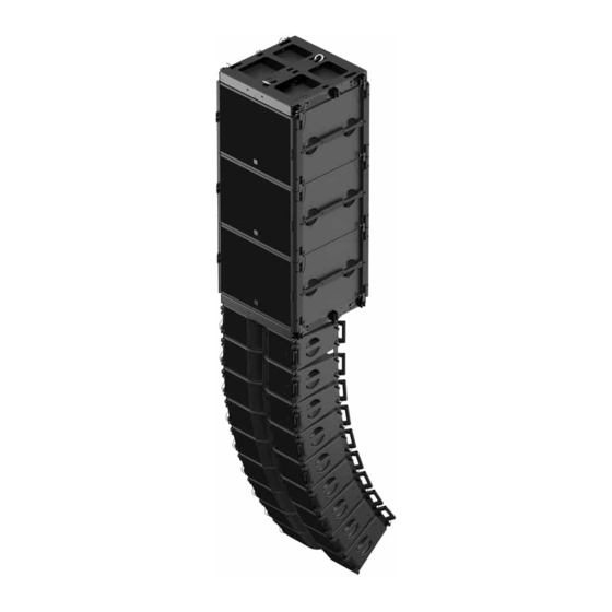
Kara II long throw line source Part of the K Series, Kara II is a modular line source system that can be deployed standalone or with its companion subwoofer SB18. Assembled as a variable curvature line source with class-leading SPL per weight and footprint, Kara II is ideal for applications that require clarity and long throw capability such as performing arts, congregations, large corporate, or special events. -
Page 9: Revision History
Initial version. Apr. 2020 Added Corrective maintenance section. Jul. 2021 • Added instructions to select the HF driver repair kit for Kara II based on the enclosure serial number. See Exploded views (p.151). • Updated maximum drive capacity for SB18 on LA8. -
Page 10: System Components
Extension bar for rigging frame M-JACK 4 tilt adjustment screw jacks with 2 angle bar extensions for stacked M-BUMP KARA-ANGARMEX 2 angle bar extension for KARA bumper KARA-MINIBU Mini bumper for flying 6 KARA Kara II owner's manual (EN) version 5.0... - Page 11 SPK2 2.3 ft / 32.8 ft / 82 ft SPK3 SPK4 DO cables DOSUB-LA8 3.5 m / 11.5 ft 3.5 m / 11.5 ft 2WAY 2W CH(A) SUB1 2W CH(B) SUB2 DOFILL-LA8 DO3WFILL Kara II owner's manual (EN) version 5.0...
- Page 12 System components Rigging accessories M-BUMP M-BAR M-JACK KARA- KARA-MINIBU KARA-MINIBUEX ANGARMEX KARA-PULLBACK Software applications Soundvision LA Network Manager Kara II owner's manual (EN) version 5.0...
-
Page 13: Electro-Acoustical Description
Electro-acoustical description Adjustable fins Kara II features L-Fins to adjust the waveguide directivity to one of four settings: 110° / 70° symmetric or 90° asymmetric (35°/55° or 55°/35°). A specific Kara II preset must be used for each directivity setting. - Page 14 Electro-acoustical description 70° setting Set the fins in the 35° position to provide the system with a 2 dB on-axis gain (> 1 kHz). 90° settings Kara II owner's manual (EN) version 5.0...
- Page 15 Electro-acoustical description Mixed settings Kara II owner's manual (EN) version 5.0...
-
Page 16: Directivity
Electro-acoustical description Directivity Horizontal Dispersion angle diagrams of one Kara II in the horizontal plane for all fins settings using lines of equal sound pressure at -3 dB, -6 dB, -12 dB. -100 -120 -140 -160 -180 1 000 10 000 Frequency (Hz) 110°... - Page 17 Electro-acoustical description -100 -120 -140 -160 -180 1 000 10 000 Frequency (Hz) 90° fins setting Kara II owner's manual (EN) version 5.0...
-
Page 18: Preset Description
Electro-acoustical description Preset description [KARA II 70] [KARA II 90] [KARA II 110] [KARA II_MO] loudspeaker elements outputs channels routing gain delay polarity mute OUT 1 IN A 0 dB 0 ms OUT 2 OUT 3 IN A 0 dB... -
Page 19: Connectors
SpeakON points Transducer LF + LF - HF + HF - connectors SB18 2 × 4-point speakON Internal pinout for L-Acoustics subwoofers SpeakON points Transducer LF + LF - Not linked Not linked connectors Kara II owner's manual (EN) version 5.0... -
Page 20: Rigging System Description
Kara II features a four-point rigging system composed of two adjustable rigging arms secured with R-BLP (round- shaped ball-locking pins) and two lodgings with R-BLP on both sides of the enclosure. Kara II can be connected to other Kara II enclosures or to dedicated rigging accessories. The inter-enclosure angle can be set between 0° and 10°. - Page 21 Rigging system description Risk of blocked ball-locking pin. Be careful not to trap the ball-locking pin tether between the rigging arm and the side handle. Kara II owner's manual (EN) version 5.0...
-
Page 22: Sb18
BLP. This change has no functional impact on rigging procedures. Illustrations in this manual may show former versions of SB18 with T-BLP. storage position rigging position rigging arm (x4) BLP (x4) SB18 features a 35 mm pole socket. Kara II owner's manual (EN) version 5.0... -
Page 23: Rigging Elements
M-BUMP Rigging structure The M-BUMP rigging structure has been designed to fly or stack the Kara II enclosures as a variable-curvature, vertical line source array. M-BUMP also allows Kara II to be rigged to an SB18 subwoofer array. M-BUMP also can fly straight vertical SB18 arrays. -
Page 24: Kara-Minibu
KARA-MINIBU Rigging structure KARA-MINIBU rigging structure has been designed to fly or stack the Kara II enclosures as a variable-curvature, vertical line source array. KARA-MINIBU also allows Kara II to be attached to an SB18 subwoofer array. KARA-MINIBU also can fly straight vertical SB18 arrays. -
Page 25: M-Bar
The M-BAR extension bar is a complementary rigging element for M-BUMP. Optionally used as a single element or in pair in flown configurations, it will extend the site angle capability of Kara II and SB18 arrays. In stacked configurations, its use is required in pairs as part of the stacking platform (see M-JACK, KARA-ANGARMEX (p.26)). -
Page 26: M-Jack, Kara-Angarmex
M-JACK consists in four feet to be used along with one M-BUMP and two M-BAR in order to form a stacking platform for a variable-curvature, vertical Kara II line source array. KARA-ANGARMEX are two angle arm extensions providing extra 10° downwards site angle for the bottom Kara II in stacked configurations. - Page 27 M-BUMP. Attach the slings to the holes shown in the figure below and respect the orientation: Front Rear When they are not used, KARA-ANGARMEX can be secured in storage position on M-BUMP with the BLP. Kara II owner's manual (EN) version 5.0...
-
Page 28: Kara-Minibuex, Kara-Angarmex
BLP. This change has no functional impact on rigging procedures. Illustrations in this manual may show former versions of KARA-ANGARMEX with T-BLP. Kara II owner's manual (EN) version 5.0... -
Page 29: Kara-Pullback
Rigging system description KARA-PULLBACK KARA-PULLBACK rigging accessory is used to set a Kara II array in a pullback configuration. It connects to the bottom enclosure of the array and to the hook or stinger of an additional motor. The KARA-PULLBACK is a plate on which is fixed one shackle fitted with 19 mm/0.75 inch-diameter axis. -
Page 30: Transportation
Transportation Flight-case It is recommended to use a flight-case designed to ship a 3-Kara II vertical array. It should contain foam inserts to prevent array movement and the tray should be fitted with 2 wedges to keep the array vertical. -
Page 31: Mechanical Safety
Mechanical safety Flown configurations The Kara II rigging system complies with 2006/42/EC: Machinery Directive. It has been designed following the guidelines of BGV-C1. 2006/42/EC: Machinery Directive specifies a safety factor of 4 against the rupture. The flown deployments described in this manual achieve a safety factor of 4 or more. -
Page 32: Assessing Mechanical Safety
Soundvision calculations are based on usual environmental conditions. A higher safety factor is recommended with factors such as extreme high or low temperatures, strong wind, prolonged exposition to salt water, etc. Always consult a rigging specialist to adopt safety practices adapted to such a situation. Kara II owner's manual (EN) version 5.0... -
Page 33: Loudspeaker Configurations
The acoustic coupling between Kara and Kara II is not optimal. Line source Deployed as a standalone line source, a Kara II system operates over the nominal bandwidth of the Kara II enclosure, with an adjustable horizontal directivity. The [KARA II 70], [KARA II 90], and [KARA II 110] presets deliver a reference frequency response in long throw applications. -
Page 34: Line Source With Low-Frequency Element
Loudspeaker configurations Line source with low-frequency element A Kara II line source can be deployed with additional subwoofer enclosures to extend the bandwidth in the low end or increase sub-low resources. Three configurations are available: • Coupled SB18 or KS21 - ratio 3:1 •... - Page 35 3 Kara II : 2 SB18 or KS21 Enclosure Kara II SB18 or KS21 Preset [KARA II 70] [KARA II 90] [KARA II 110] [xxxx_60] 32 Hz - 20 kHz with SB18 Frequency range (-10 dB) 29 Hz - 20 kHz with KS21...
- Page 36 Kara II = 0.5 ms KS21 = 0 ms [KARA II] + [KS21_60_C] Kara II = 6 ms KS21 = 0 ms [KARA II] + [KS21_60_Cx] Kara II = 5.5 ms KS21 = 0 ms Kara II owner's manual (EN) version 5.0...
- Page 37 Refer to the subwoofer owner's manual and to the Cardioid configurations technical bulletin. KS21 cannot be mechanically coupled with a Kara II line source in an array. The KS21 and Kara II arrays must be flown independently. Refer to the KS21 owner's manual for more information on how to set up a KS21 array.
-
Page 38: Line Source Element
[KS28_60_Cx] Line source element One or two Kara II can be used as a line source element. In this configuration, the system operates without the low-end of the bandwidth. The [KARA II_FI] presets delivers a flat frequency response for short throw applications and a high-pass filter at 100 The [KARA II_FI] preset is optimized for a 110°... -
Page 39: With Low-Frequency Element
[KS21_100] presets provide SB18 and KS21 with an upper frequency limit at 100 Hz. The [KARA II_FI] preset is optimized for a 110° fins setting (see Adjustable fins (p.13)). The Kara II, SB18, and KS21 enclosures are driven by the LA4X / LA12X amplified controllers. Enclosure Kara II SB18 or KS21... -
Page 40: Stage Monitor
KS21 = 0 ms Stage monitor Up to three Kara II can be used as a stage monitor. In this configuration, the system operates over the nominal bandwidth of the enclosure. The [KARA II_MO] preset delivers a reference frequency response in stage monitoring applications. -
Page 41: With Low-Frequency Element
[KS21_60] presets provide SB18 and KS21 with an upper frequency limit at 60 Hz. The [KARA II_MO] preset is optimized for a 110° fins setting (see Adjustable fins (p.13)). The Kara II, SB18, and KS21 enclosures are driven by the LA4X / LA12X amplified controllers. Enclosure Kara II SB18 or KS21... -
Page 42: Inspection And Preventive Maintenance
• transportation accessories This inspection procedure covers only L-Acoustics products. To inspect other products that are part of the lifting chain, refer to the manufacturer's instructions. Prerequisite Perform the inspection in a well-lit environment. -
Page 43: Mechanical System Overview
5. Check the moving parts. Make sure that the mechanism engages correctly. What to do next If a problem is detected, perform the authorized maintenance operations or contact your L-Acoustics representative. Mechanical system overview Critical parts of the lifting chains are highlighted. -
Page 44: Mixed Kara Ii Array With Sb18 And M-Bump
Inspection and preventive maintenance Mixed Kara II array with SB18 and M-BUMP Ball-locking pins (p.47) Shackles (p.49) Ball-locking pins (p.47) Ball-locking pins (p.47) Rigging check (p.50) Ball-locking pins (p.47) Kara II owner's manual (EN) version 5.0... -
Page 45: Mixed Kara Ii Array With Sb18, Kara-Minibu/Kara-Minibuex And Kara-Pullback
Inspection and preventive maintenance Mixed Kara II array with SB18, KARA-MINIBU/KARA-MINIBUEX and KARA-PULLBACK Shackles (p.49) screws are tightened Ball-locking pins (p.47) Ball-locking pins (p.47) Ball-locking pins (p.47) Rigging check (p.50) Ball-locking pins (p.47) tabs are not bent Shackles (p.49) Kara II owner's manual (EN) version 5.0... -
Page 46: Stacked Kara Ii Array With M-Bump, M-Jack And Kara-Angarmex
Inspection and preventive maintenance Stacked Kara II array with M-BUMP, M-JACK and KARA-ANGARMEX Ball-locking pins (p.47) Rigging check (p.50) Ball-locking pins (p.47) Ball-locking pins (p.47) Ball-locking pins (p.47) safety pin is present Kara II owner's manual (EN) version 5.0... -
Page 47: Inspection References
Inspection and preventive maintenance Inspection references Ball-locking pins Reference pictures Check that the ball-locking pin tethers are intact and safely secured. Kara II SB18 M-BUMP KARA-MINIBU M-BAR KARA-MINIBUEX KARA- ANGARMEX Kara II owner's manual (EN) version 5.0... - Page 48 The pin must remain inside the hole. If the pin is inserted in two plates, the ball must pass through both plates and lock the pin in place. If the check fails, immediately withdraw the product from use and contact L-Acoustics. Related tasks Rigging part inspection (p.42)
-
Page 49: Shackles
Inspection and preventive maintenance Shackles Moving parts Drive the shackle axis in its lodging. Make sure that the end is flush with the shackle. Related tasks Rigging part inspection (p.42) Kara II owner's manual (EN) version 5.0... -
Page 50: Rigging Check
Inspection and preventive maintenance Rigging check Prerequisite Check that the front rigging plates of the Kara II enclosure are not loose. Procedure 1. Secure the front rigging arms at rigging position. The rigging arms slide and rotate correctly. 2. Secure the rear rigging arms at the 0° position. - Page 51 Inspection and preventive maintenance The rigging arms slide correctly. 3. Secure a second Kara II on top of the first Kara II. 4. Hold the top enclosure by the handles and shake the assembly. The two enclosures remain attached. 5. Remove the ball-locking pins of the top enclosure to separate it from the bottom enclosure.
-
Page 52: Acoustical Check
6. Launch the ENCLOSURE CHECK. The amplified controller generates short sinusoidal signals simultaneously for each connected output. The amplified controller displays the results for each output. Kara II owner's manual (EN) version 5.0... - Page 53 (found in NOK and UNDEF results) • the number of operational transducers out of the total Low variations from the expected range are acceptable: displayed percentage can be different from 0 and all transducers considered operational. Kara II owner's manual (EN) version 5.0...
-
Page 54: Listening Test
4. Carefully clean the speaker with a dry cloth. 5. Perform the reassembly procedure. Replace the speaker gasket and the screws. Apply the recommended torque. 6. Repeat the listening test. If the problem persists, replace the speaker. Kara II owner's manual (EN) version 5.0... - Page 55 3. Clean the air gap thoroughly. Use double-face adhesive tape to remove any particles. 4. Perform the diaphragm reassembly procedure. Apply the recommended torque. 5. Repeat the listening test. If the problem persists, replace the driver. Kara II owner's manual (EN) version 5.0...
-
Page 56: Rigging Procedures
• Check the mechanical conformity of the system. The M-BUMP can nominally fly an array of up to 24 Kara II along with all loudspeakers cables (refer to Mechanical safety (p.31)). However, this maximum number can decrease in line with the array curvature. - Page 57 II#3 from top to bottom. 5. Check the inter-enclosure connections in ARRAY#1 (repeat for each side): a) For both front rigging points, verify that the front arm is open and locked to two Kara II by two R-BLP inserted in yellow link holes.
- Page 58 For both rear rigging points, verify that the angle arm cursor is aligned with the 0° angle value and locked to two Kara II by two R-BLP, the upper one inserted in a yellow link hole and the bottom one inserted into angle hole 0°/2°/4°.
- Page 59 It is recommended to select the 5° angle on the Kara II intended to be linked to the M-BUMP. By doing this, the Kara II#1 axis is parallel to the M-BUMP, so that a laser secured on M-BUMP can give the site angle of the Kara II#1 enclosure.
- Page 60 11. Check the inter-enclosure connections in ARRAY#2 by applying step (p.57). 12. On Kara II#4, take both front arms out as follows (repeat for each one): remove the front top R-BLP, rotate the front arm up, and slide it down. Do not insert back the R-BLP.
- Page 61 ARRAY#1 and ARRAY#2 as follows: a) Remove the Kara II#4 rear top R-BLP from its storage position, slide the angle arm so as to align the cursor with the desired angle value, and secure by inserting the R-BLP into the corresponding angle hole (0°/2°/4° or 1°/3°/5°/7.5°/10°).
- Page 62 KARA-PULLBACK studs into the Kara II rigging points (long studs at the back), remove the 4 bottom R-BLP from the Kara II and secure by inserting them into the bottom yellow link holes. Attach the hook or stinger of an additional motor to the KARA-PULLBACK shackle.
- Page 63 KARA-PULLBACK remove the 4 bottom R-BLP from the bottom Kara II, insert them back into the bottom storage holes, and remove the KARA-PULLBACK.
- Page 64 Rotate ARRAY#2 downwards and place the rear corners into the tray while still suspended from the front rigging points. c) Remove the rear top angle R-BLP from Kara II#4, slide the angle arm so as to align the cursor with the storage position, and insert the R-BLP into the top storage hole.
- Page 65 R-BLP into the top storage hole. b) On each side of the Kara II#1, remove the rear top angle R-BLP, slide the angle arm so as to align the cursor with the storage position, and secure by inserting the R-BLP into the top storage hole.
- Page 66 Re-insert the four short BLP in their storage locations. b) Remove each M-BAR as follows: remove both T-BLP from the M-BAR studs, remove the M-BAR, and insert both T-BLP back in their storage locations. Kara II owner's manual (EN) version 5.0...
-
Page 67: Using Kara-Minibu
Procedure 1. Bring a full Kara II flight-case to the rigging location and remove the lid. Direct the front face of the Kara II array towards the audience. In the following, the array will be designated as ARRAY#1 and the enclosures as Kara II#1 to Kara II#3 from top to bottom. - Page 68 A link hole is indicated by a yellow circle. b) Verify that each angle arm (x2) has the cursor aligned with the 0° angle label and is secured to two Kara II by two R-BLP, the top one being inserted into the link hole and the bottom one into angle hole 0°/2°/4°.
- Page 69 (towards audience). c) While keeping this orientation, align the four link points of KARA-MINIBU with the four arms of Kara II#1 and secure each pair together by inserting the four R-BLP back into the same holes (insert both rear R-BLP first).
- Page 70 Repeat the procedure for Kara II#3. 9. Bring another full Kara II flight-case to the rigging location and remove the lid. Direct the front face of the Kara II array towards the audience. In the following, the array will be designated as ARRAY#2 and the enclosures as Kara II#4 to Kara II#6 from top to bottom.
- Page 71 ARRAY#2 as follows: a) Remove the Kara II#4 rear top R-BLP from its storage hole, slide the angle arm so as to align the cursor with the chosen angle label, and lock it in place by inserting the R-BLP into the corresponding angle hole (0°/2°/4°...
- Page 72 16. Set the inter-enclosure angles in ARRAY#2 by applying step (p.70). 17. If the array is intended to be flown in pullback configuration, attach a KARA-PULLBACK to the bottom Kara II as follows: a) Align the KARA-PULLBACK studs with the Kara II link points (long studs at the back).
- Page 73 Rotate ARRAY#2 downwards and position the rear corners into the tray while still suspended from the front link points. c) Remove the Kara II#4 rear top R-BLP from its angle hole, slide the angle arm so as to align the cursor with the storage label, and insert the R-BLP back into its storage hole.
- Page 74 Slightly raise ARRAY#1 so that it is no longer in contact with ARRAY#2. c) Remove both Kara II#3 front bottom R-BLP from their link holes and insert them back into their storage holes. d) Rotate both Kara II#4 front arms down and insert both front top R-BLP back into their storage holes.
- Page 75 Remove the four R-BLP from the KARA-MINIBU. c) Remove the KARA-MINIBU from Kara II#1 and insert the four R-BLP back into the same holes. 15. Close the four Kara II#1 arms as follows (repeat on both sides of the enclosure): a) Remove the front top R-BLP from its link hole, slide the front arm up, rotate it down, and lock it in place by inserting the R-BLP back into its storage hole.
-
Page 76: Flying An Sb18/Kara Ii Mixed Array Or An Sb18 Standalone Array
Calculate the array site angle and the inter-enclosure angles. • Check the mechanical conformity of the system. The M-BUMP can nominally fly an array of up to 4 SB18/12 Kara II or 16 SB18 along with all loudspeakers cables (refer to Mechanical safety (p.31)). - Page 77 Attach the four rigging arms of SB18#2 to SB18#1 as follows: disconnect a BLP from SB18#2, rotate the rigging arm up, connect the BLP back to the SB18#1 rigging point and the rigging arm ; repeat this procedure until all 4 arms are secured. Kara II owner's manual (EN) version 5.0...
- Page 78 Rigging procedures Kara II owner's manual (EN) version 5.0...
- Page 79 Repeat this procedure until all four arms are secured. 6. Attach the motor hook(s) or stinger(s) to the shackle(s). 7. Raise the array so that it is possible to place another stack of two SB18 under it. Kara II owner's manual (EN) version 5.0...
- Page 80 (p.79) to 9 until all SB18 composing the array are rigged. b) Raise the array to the desired height. c) Secure the M-BUMP to the main rigging structure using two safety slings (not provided). Kara II owner's manual (EN) version 5.0...
- Page 81 For clarity purposes, the procedure is continued with an array composed of two SB18 enclosures. 11. Check the inter-enclosure connections in ARRAY#1 (repeat for each side): a) For both front rigging points, verify that the front arm is open and locked to 2 Kara II by 2 R-BLP inserted in yellow link holes.
- Page 82 It is recommended to select the 5° angle on the Kara II intended to be linked to the M-BUMP. By doing this, the Kara II#1 axis is parallel to the M-BUMP, so that a laser secured on M-BUMP can give the site angle of the Kara II#1 enclosure.
- Page 83 16. Raise the array to a height for which the angle arms of ARRAY#1 are within comfortable reach and remove the flight-case from the rigging location. 17. Continue the procedure by applying Kara II standalone array mounting procedure, steps (p.60) to 21.
- Page 84 1. In case of SB18 standalone array, directly go to step (p.85). In case of SB18/Kara II mixed array, begin the procedure by applying the Kara II standalone array removal procedure, steps (p.63) to 13, and then continue to next step.
- Page 85 R-BLP back into the top storage hole. b) On each side of the Kara II#1, remove the rear top angle R-BLP, slide the angle arm so as to align the cursor with the storage position, and secure by inserting the R-BLP back into the top storage hole.
- Page 86 (p.85) to 14 to separate the SB18s from the array just until SB18#1 and 2 are remaining attached to the M-BUMP. 16. Lower the array until it rests on the ground. 17. Remove the motor hook(s) or stinger(s) from the shackle(s) of the M-BUMP. Kara II owner's manual (EN) version 5.0...
- Page 87 BAR studs, remove the M-BAR, and insert both T-BLP back in their storage locations. 20. Attach two dolly boards to SB18#1 and 2. 21. Detach SB18#2 from SB18#1 by applying step (p.86) and remove both subwoofers from the rigging location. Kara II owner's manual (EN) version 5.0...
-
Page 88: Using Kara-Minibu
Calculate the array site angle and the inter-enclosure angles. • Check the mechanical conformity of the loudspeaker assembly. The KARA-MINIBU/KARA-MINIBUEX structure can nominally fly an array of up to 2 SB18/6 Kara II or 4 SB18 along with all loudspeakers cables (refer to Mechanical safety (p.31)). - Page 89 Remove a BLP from SB18#2, rotate the link arm up, then insert the BLP into the SB18#1 link point and the link arm. Repeat this step until all four arms are secured. Kara II owner's manual (EN) version 5.0...
- Page 90 Re-insert the four BLP into the KARA-MINIBUEX link points and the SB18#1 link arms. 4. Attach the motor hook(s) or stinger(s) to the shackle(s) and raise the array to a height of 1.3 m/4.3 ft. 5. If the array is intended to be an SB18/Kara II mixed array, directly go to step (p.91).
- Page 91 8. Secure the KARA-MINIBU to the main rigging structure by using two safety slings (not included). 9. Bring a full Kara II flight-case to the rigging location and remove the lid. Direct the front face of the Kara II array towards the audience.
- Page 92 5°, and lock it in place by inserting the R-BLP into angle hole 1°/3°/5°/7.5°/10°. It is recommended to select the 5° angle on the Kara II intended to be attached to the KARA-MINIBU. By doing this, the Kara II#1 axis is parallel to the KARA-MINIBU, so that a laser secured on KARA-MINIBU can give the site angle of the Kara II#1 enclosure.
- Page 93 Rigging procedures c) While keeping this orientation, align the four link points of KARA-MINIBU with the four arms of Kara II#1 and secure each pair together by inserting the four R-BLP back into the same holes (insert both rear R-BLP first).
- Page 94 Rigging procedures 16. Continue the procedure by applying the Kara II standalone array mounting procedure Array mounting (p.67), steps (p.70) to 19. Kara II owner's manual (EN) version 5.0...
- Page 95 1. If the array to disassemble is an SB18 standalone array, directly go to step (p.96). If the array to disassemble is an SB18/Kara II mixed array, begin the procedure by applying the Kara II standalone array removal procedure, steps (p.73) to 12, and then continue from step...
- Page 96 Re-insert the four R-BLP into the same KARA-MINIBU holes. 6. Close the four Kara II#1 arms as follows (repeat on both sides of the enclosure): a) Remove the front top R-BLP from its link hole, slide the front arm up, rotate it down, and lock it in place by inserting the R-BLP back into its storage hole.
- Page 97 13. Remove SB18#4 from SB18#3 by applying step (p.97). 14. Remove SB18#3 and SB18#4 from the rigging location. 15. Lower the array until it rests on the ground. 16. Detach the motor hook(s) or stinger(s) from the KARA-MINIBU shackle(s). Kara II owner's manual (EN) version 5.0...
- Page 98 Lock the link arms in closed position by inserting the four BLP back into the top SB18#1 link points. 18. Attach a dolly board to each of the SB18#1 and SB18#2 subwoofers. 19. Remove SB18#2 from SB18#1 by applying step (p.97) and remove both subwoofers from the rigging location. Kara II owner's manual (EN) version 5.0...
-
Page 99: Stacking A Kara Ii Standalone Array
A platform stacked array can be composed of a maximum of 9 Kara II enclosures along with all loudspeakers cables (refer to Mechanical safety (p.31)). The platform must be installed in rear extension configuration if the Kara II array is intended to have a positive site angle (refer to Stacking platform configuration (p.186)). - Page 100 Place an M-JACK under one end of an M-BAR and align the M-JACK hole with the second M-BAR hole. c) Secure M-JACK to M-BAR with the axis and safety pin. Lock the safety pin. d) Repeat the procedure to attach a second M-JACK to the other end of the M-BAR. Kara II owner's manual (EN) version 5.0...
- Page 101 Insert the single part of the KARA-ANGARMEX into the M-BUMP by putting it vertically with sling ring pointing towards the front and indentation on the spacer. c) Align the KARA-ANGARMEX and M-BUMP holes. Insert the M-BUMP BLP. Kara II owner's manual (EN) version 5.0...
- Page 102 6. Remove both front short BLP from the M-BUMP. If the M-BUMP has been configured without KARA-ANGARMEX, also remove both rear short BLP. 7. Place a full Kara II flight-case at the stacking location and remove the lid. In the following, the enclosures will be designated as Kara II#1 to Kara II#3 from top to bottom.
- Page 103 Be careful not to trap the ball-locking pin tether between the rigging arm and the side handle. c) Remove the front and rear bottom link R-BLP and insert them back into the bottom storage holes. Kara II owner's manual (EN) version 5.0...
- Page 104 9. Link Kara II#1 to the M-BUMP as follows: a) Lift up Kara II#1 and turn it arms downwards and front face towards the audience. b) Insert the four arms into the M-BUMP rigging points. If the M-BUMP has been configured with KARA- ANGARMEX, the rear rigging points become those of the KARA-ANGARMEX.
- Page 105 Secure the four rigging points by removing the four Kara II#1 top R-BLP from their storage holes and reinserting them into the top yellow link holes. 12. Link Kara II#3 to Kara II#2 by applying steps 10 and 11 (do not remove the 4 bottom R-BLP from Kara II#3). Kara II owner's manual (EN) version 5.0...
- Page 106 Rigging procedures 13. Using other full Kara II flight-cases, repeat steps (p.104) and (p.105) until all Kara II enclosures composing the array are rigged. 14. Check if the stacking platform is still horizontal. If not, refer to step (p.101). 15. Secure the system to a fixed point using a ratchet strap or any other applicable material (not included).
- Page 107 2. Place an empty Kara II flight-case at the rigging location and remove the lid. 3. Separate the top Kara II (Kara II#3 for example) from the Kara II below (Kara II#2 for example) as follows: remove the 4 top link R-BLP from Kara II#2 and insert them back into the top storage holes.
- Page 108 Rigging procedures 5. Set the angle to 0° on Kara II#3 as follows (repeat for each side): remove the rear top angle R-BLP, slide the angle arm so as to align the cursor with the 0° angle value, and secure by inserting the R-BLP into angle hole 0°/2°/4°.
- Page 109 Rigging procedures 9. Separate Kara II#1 from the M-BUMP as follows (or repeat the procedure from step (p.107) if the top enclosure is not Kara II#1): a) Remove both front short BLP from the M-BUMP. b) Depending on the configuration, remove either both short BLP from the M-BUMP or both T-BLP from the KARA-ANGARMEX.
- Page 110 R-BLP on the top storage hole. b) On both sides of Kara II#1, remove the rear top R-BLP, slide the angle arm so as to align the cursor with the storage position, and secure by inserting the top R-BLP on the top storage hole.
- Page 111 Lift up the corresponding side of the M-BUMP and remove the M-BAR. c) Re-insert both T-BLP into their storage holes. 15. Remove both M-JACK from each M-BAR. On each M-JACK, unlock the safety pin and remove the safety pin and the axis. Kara II owner's manual (EN) version 5.0...
-
Page 112: Using Kara-Minibu
Mechanical safety (p.31)) within the following setup safety limits: • If the Kara II array is flat (all inter-enclosure angles are close to 0°), the platform must be installed in front extension configuration (refer to Stacking platform configuration (p.188)) and the site angle of the bottom Kara II... - Page 113 4. If KARA-ANGARMEX are attached to the KARA-MINIBU, remove both BLP from them. Otherwise, remove both rear R-BLP from the KARA-MINIBU. 5. Bring a full Kara II flight-case to the stacking location and remove the lid. In the following, the enclosures will be designated as Kara II#1 to Kara II#3 from top to bottom.
- Page 114 Rigging procedures 6. Open the four Kara II#1 arms as follows (repeat on both sides of the enclosure): a) Remove the front top R-BLP from its storage hole, rotate the front arm up, slide it down, and lock it in place by inserting the R-BLP into its link hole.
- Page 115 (p.189) to obtain the angle value corresponding to the chosen array site angle. 7. Attach the platform to Kara II#1 as follows: a) Turn the platform feet pointing up and position it above Kara II#1 according to the chosen configuration (see Stacking platform configuration (p.188)).
- Page 116 Rigging procedures Kara II owner's manual (EN) version 5.0...
- Page 117 10. Open the four Kara II#2 arms by applying step (p.114). 11. Remove the four Kara II#2 bottom R-BLP from their link holes and insert them back into their storage holes (see step (p.117)). Kara II owner's manual (EN) version 5.0...
- Page 118 Turn Kara II#2 arms pointing down and front face towards the audience. b) Align the four arms with the Kara II#1 link points. c) Secure the link points together by removing the four Kara II#1 top R-BLP from their storage holes and reinserting them into their link holes.
- Page 119 Rigging procedures 14. Using another full Kara II flight-case, repeat steps (p.117) to 12 until all Kara II enclosures composing the array are assembled. Rear extension configuration Front extension configuration 15. Secure the array to a fixed point by using a ratchet strap or any other equivalent material (not included).
- Page 120 2. Bring an empty Kara II flight-case to the rigging location and remove the lid. 3. Remove the top Kara II (Kara II#3 for example) from the Kara II below (Kara II#2 for example) by removing the four Kara II#2 top R-BLP from their link holes and inserting them back into their storage holes.
- Page 121 8. Set angles 0° on Kara II#2 by applying step (p.121). 9. If the last Kara II to be placed in the flight-case is not attached to the KARA-MINIBU (Kara II#4), apply steps (p.120), (p.121), (p.123), and...
- Page 122 Rigging procedures 10. Remove the platform from Kara II#1 as follows: a) Remove both KARA-MINIBU front R-BLP. b) If KARA-ANGARMEX are attached to the platform, remove both BLP from them. Otherwise, remove both KARA-MINIBU rear R-BLP. c) Remove the platform from Kara II#1.
- Page 123 Rigging procedures 11. Close the four Kara II#1 arms as follows (repeat on both sides of the enclosure): a) Remove the front top R-BLP from its link hole, slide the front arm up, rotate it down, and lock it in place by inserting the R-BLP back into its storage hole.
-
Page 124: Stacking An Sb18/Kara Ii Mixed Array Or An Sb18 Standalone Array
Using M-BUMP Modeling and safety An SB18/Kara II mixed array or an SB18 standalone array can be stacked directly on the ground (ground stacked array) or onto an M-BUMP/M-BAR/M-JACK platform (platform stacked array). The figure below shows a mixed array of each type and gives the associated conditions of use. - Page 125 A maximum of 4 SB18 can be platform-stacked. Refer to the Soundvision model to assess the mechanical safety of a platform-stacked SB18/Kara II mixed array. The platform must be installed in rear extension configuration if a Kara II array is intended to be rigged with a positive site angle (refer to Stacking platform configuration (p.186)).
- Page 126 2. Mount two M-BAR/M-JACK assemblies as follows (repeat for each M-BAR): a) Remove the axis and safety pin from M-JACK. b) Place an M-JACK under one end of an M-BAR and align the M-JACK hole with the second M-BAR hole. Kara II owner's manual (EN) version 5.0...
- Page 127 Lift up one side of the M-BUMP, place the M-BAR beneath it with M-JACK on the ground, and lower the M- BUMP so as to insert both M-BAR studs into the M-BUMP slits. c) Secure by inserting both preceding T-BLP. Kara II owner's manual (EN) version 5.0...
- Page 128 Link the four rigging arms of SB18#1 to the M-BUMP as follows: disconnect a BLP from SB18#1, rotate the rigging arm down, connect the BLP to the M-BUMP rigging point and the rigging arm ; repeat this procedure until all 4 arms are secured. Kara II owner's manual (EN) version 5.0...
- Page 129 Attach the four rigging arms of SB18#2 to SB18#1 as follows: disconnect a BLP from SB18#2, rotate the rigging arm down, connect the BLP back to the SB18#1 rigging point and the rigging arm; repeat this procedure until all 4 arms are secured. Kara II owner's manual (EN) version 5.0...
- Page 130 Secure the system to a fixed point using a ratchet strap or any other applicable material (not provided). If the array is intended to be an SB18/Kara II mixed array, place a second M-BUMP at the rigging location. Turn it so that the text of the identification plate is upside down and the laser slits are directed towards the audience, and place it on the top SB18.
- Page 131 BLP from the M-BUMP, rotate the arm downwards and secure it to the SB18 by inserting back the BLP. 10. Finish the procedure by applying steps (p.101) to 15 from the Array mounting procedure in Stacking a Kara II standalone array using M-BUMP.
- Page 132 (p.107) to 13 from the Array removal procedure in Stacking a Kara II standalone array using M-BUMP and then continue to next step. 2. Unlink the 4 rigging points between the M-BUMP and the SB18 as follows (repeat for each one): remove the BLP from the SB18, rotate the arm upwards and lock it by inserting the BLP on the M-BUMP.
- Page 133 Lift up the corresponding side of the M-BUMP and remove the M-BAR. c) Re-insert both T-BLP into their storage holes. 9. Remove both M-JACK from each M-BAR. On each M-JACK, unlock the safety pin and remove the safety pin and the axis. Kara II owner's manual (EN) version 5.0...
-
Page 134: Using Kara-Minibu
Using KARA-MINIBU Modeling and safety An SB18/Kara II mixed array or an SB18 standalone array must be stacked directly on the ground (ground stacked array). Any SB18/Kara II ground stacked array must be modeled before installation so as to ensure acoustical and mechanical conformity. - Page 135 Drive 3 bolts to the 3 holes shown in the figure below (6 mm hex bit, 13 mm hex key, 7 N.m/63 in.lbf). d) Repeat the procedure with a second KARA-MINIBUEX on the other side of the KARA-MINIBU. Put the stacking platform in rear extension configuration only (see Stacking platform configuration (p.188)). Kara II owner's manual (EN) version 5.0...
- Page 136 8. If KARA-ANGARMEX are attached to the KARA-MINIBU, remove both BLP from them. Otherwise, remove both rear R-BLP from the KARA-MINIBU. 9. Bring a full Kara II flight-case to the stacking location and remove the lid. In the following, the enclosures will be designated as Kara II#1 to Kara II#3 from top to bottom.
- Page 137 Rigging procedures 10. Open the four Kara II#1 arms as follows (repeat on both sides of the enclosure): a) Remove the front top R-BLP from its storage hole, rotate the front arm up, slide it down, and lock it in place by inserting the R-BLP into its link hole.
- Page 138 Rigging procedures 11. Attach the platform to Kara II#1 as follows: a) Turn the platform feet pointing up and position it above Kara II#1 in rear extension configuration (see Stacking platform configuration (p.188)). b) Lower the platform to slide the four KARA-MINIBU slits along the Kara II#1 arms.
- Page 139 Rigging procedures 12. Remove the four Kara II#1 bottom R-BLP from their link holes and insert them back into their storage holes. Kara II owner's manual (EN) version 5.0...
- Page 140 14. Open the four Kara II#2 arms by applying step (p.137). 15. Remove the four Kara II#2 bottom R-BLP from their link holes and insert them back into their storage holes (see step (p.139)).
- Page 141 Turn Kara II#2 arms pointing down and front face towards the audience. b) Align the four arms with the Kara II#1 link points. c) Secure the link points together by removing the four Kara II#1 top R-BLP from their storage holes and reinserting them into their link holes.
- Page 142 Rigging procedures 18. Using another full Kara II flight-case, repeat steps (p.140) to (p.141) until all Kara II enclosures composing the array are assembled. 19. Secure the loudspeaker assembly to a fixed point using a ratchet strap or any other equivalent material (not included).
- Page 143 2. Bring an empty Kara II flight-case to the rigging location and remove the lid. 3. Remove the top Kara II (Kara II#3 for example) from the Kara II below (Kara II#2 for example) by removing the four Kara II#2 top R-BLP from their link holes and inserting them back into their storage holes.
- Page 144 Lift up and turn Kara II#2 arms pointing up. b) Align the front and rear link points between Kara II#2 and Kara II#3. c) Secure the link points together by removing the four Kara II#2 bottom R-BLP from their storage holes and reinserting them into their link holes.
- Page 145 Rigging procedures 9. If the last enclosure to be placed in the flight-case is not attached to the KARA-MINIBU (Kara II#4), apply steps (p.143), (p.144), (p.147), and (p.147) for Kara II#4 and then apply the procedure a new time from step (p.143) for array Kara II#1-3.
- Page 146 Rigging procedures 11. Remove the platform from Kara II#1 as follows: a) Remove both KARA-MINIBU front R-BLP. b) If KARA-ANGARMEX are attached to the platform, remove both BLP from them. Otherwise, remove both KARA-MINIBU rear R-BLP. c) Separate the platform from Kara II#1.
- Page 147 Rigging procedures 12. Close the four Kara II#1 arms as follows (repeat on both sides of the enclosure): a) Remove the front top R-BLP from its link hole, slide the front arm up, rotate it down, and lock it in place by inserting the R-BLP back into its storage hole.
-
Page 148: Connection To La Amplified Controllers
2W CH(A) 2W CH(B) Four-channel CA-COM output for one Kara II and two subwoofers For passive loudspeakers, the value corresponds to the number of enclosures in parallel on the output. For active loudspeakers, the value corresponds to the number of sections in parallel on the output. - Page 149 Refer to the cabling schemes to connect the enclosures to different types of output connectors. One-channel speakON output 1+/1- Two-channel speakON output CH(1) SP-Y1 CC4FP CH(2) 1+/1- 2+/2- Four-channel CA-COM output SPK1 SPK2 SPK3 SPK4 Kara II owner's manual (EN) version 5.0...
-
Page 150: Corrective Maintenance
The Maintenance Toolcase includes tools manufactured by FACOM ® , Fluke ® , Tohnichi, ABUS, and Würth. All third-party trademarks, registered trademarks, or product names are the property of their respective owners. Kara II owner's manual (EN) version 5.0... -
Page 151: Exploded Views
Reassembly (D/R) procedure and the necessary repair kit (KR). Checking KR compatibility The G03521 and G03520 repair kits are compatible only with Kara II(i) and not with Kara enclosures that were upgraded to Kara II using the KARA II UPG kit. - Page 152 Corrective maintenance CONNECTOR PLATE HF DRIVER HF DIAPHRAGM G03521 G03520 Kara II owner's manual (EN) version 5.0...
-
Page 153: Disassembly And Reassembly Procedures
• torque screwdriver • T30 Torx bit Repair kit G03616 KR loudspeaker 8" Kara(i) / Kara II(i) ×4 S221 M6×35 Torx Exploded view For safety reasons, always use the new screws and spare parts provided in the KR. If no new screws are available, use blue threadlocker. - Page 154 • T30 Torx bit • flat plastic tool Repair kit G03616 KR loudspeaker 8" Kara(i) / Kara II(i) ×2 S100143 M6×25 Torx Exploded view For safety reasons, always use the new screws and spare parts provided in the KR. If no new screws are available, use blue threadlocker.
- Page 155 Corrective maintenance D/R - LF speaker Tools • torque screwdriver • T25 Torx bit Repair kit G03616 KR loudspeaker 8" Kara(i) / Kara II(i) ×1 ×4 ×2 18435 S100228 1707 8" LF/MF speaker - 16 Ω M5x25 Torx 8" speaker gasket Prerequisite Grill removed.
- Page 156 Tools • torque screwdriver • T30 Torx bit Repair kit G03521 - KR compression driver 3" Kara II(i) or G03520 - KR diaphragm for 3" driver Kara II(i) ×6 S221 M6×35 Torx Exploded view For safety reasons, always use the new screws and spare parts provided in the KR.
- Page 157 ×2 D17986 S247 3" HF driver - 8 ohms assembly M6×35 Torx * The screws and fasteners are also provided in G03520 (KR diaphragm for 3" driver Kara II(i)). Prerequisite Connector plate removed. D/R - Connector plate (p.156). Exploded view For safety reasons, always use the new screws and spare parts provided in the KR.
- Page 158 • 3 mm hex bit • compressed air blower Consumables • double face adhesive tape Repair kit G03520 KR diaphragm for 3" driver Kara II(i) ×1 ×4 17581 S100082 diaphragm assembly (with 2 shims) M4×14 hex Prerequisite Connector plate removed.
- Page 159 Tighten the screws in the same order with the torque screwdriver. Use the 3 mm hex bit. Set the torque to 3 N.m. What to do next Perform the Acoustical check (p.52) procedures. Kara II owner's manual (EN) version 5.0...
-
Page 160: Sb18
SB18 Exploded view In order to operate, follow the order outlined here. Each assembly refers to the corresponding Disassembly/ Reassembly (D/R) procedure and the necessary repair kit (KR). LF speaker KR HPBC182 Grill Kara II owner's manual (EN) version 5.0... - Page 161 KR 18" loudspeaker SB18(i) / SB18 IIi ×4 S247 M6×35 Torx Exploded view For safety reasons, always use the new screws and spare parts provided in the KR. If no new screws are available, use blue threadlocker. 3 N.m Kara II owner's manual (EN) version 5.0...
- Page 162 KR 18" loudspeaker SB18(i) / SB18 IIi ×1 ×8 ×14 ×4 S100054 S221 100689 18" speaker - 8 ohms M6×30 hex M6×35 Torx 18" speaker gasket Prerequisite Grill disassembled. D/R - Grill (p.161). Disassembly Procedure 1. Remove the plate. Kara II owner's manual (EN) version 5.0...
- Page 163 Corrective maintenance 2. Remove the screws securing the speaker. 5 mm 3. Remove the speaker from the enclosure and disconnect the speaker cables. 4. If the speaker gaskets are damaged, remove and replace them. Kara II owner's manual (EN) version 5.0...
- Page 164 1. Stick the gasket on the cabinet. 2. Connect the speaker cables and position the speaker in the enclosure. 3. Secure the speaker. Gradually tighten the screws following a star pattern. 5 N.m 5 mm Kara II owner's manual (EN) version 5.0...
- Page 165 Corrective maintenance 4. Secure the plate. Gradually tighten the screws following a star pattern. Kara II owner's manual (EN) version 5.0...
-
Page 166: Specifications
2-way active WST enclosure: 2 × 8" LF + 3" HF diaphragm, amplified by LA4X / LA12X Usable bandwidth (-10 dB) 55 Hz - 20 kHz ([KARA II 70]) Maximum SPL 142 dB ([KARA II 70]) Nominal directivity (-6 dB) horizontal: 70°... - Page 167 Specifications Kara II dimensions 733 mm / 28.9 in 252 mm / 9.9 in 482 mm / 19 in Kara II owner's manual (EN) version 5.0...
- Page 168 Rigging components steel with anti-corrosion coating Finish dark grey brown Pantone 426 C IP55 Peak level at 1 m under half space conditions using pink noise with crest factor 4 (preset specified in brackets). Kara II owner's manual (EN) version 5.0...
- Page 169 Specifications SB18 dimensions 707 mm / 27.8 in 750 mm / 29.5 in Kara II owner's manual (EN) version 5.0...
- Page 170 Finish dark grey brown Pantone 426 C IP55 Peak level at 1 m under half space conditions using pink noise with crest factor 4 (preset specified in brackets). Kara II owner's manual (EN) version 5.0...
- Page 171 Specifications KS21 dimensions 764 mm / 30 in 602 mm / 23.7 in 752 mm / 29.6 in Kara II owner's manual (EN) version 5.0...
- Page 172 Rigging components high grade steel Finish dark grey brown Pantone 426 C IP55 Peak level at 1 m under half space conditions using pink noise with crest factor 4 (preset specified in brackets). Kara II owner's manual (EN) version 5.0...
- Page 173 Specifications KS28 dimensions 1340 mm / 52.8 in 702 mm / 27.6 in 1351 mm / 53.2 in Kara II owner's manual (EN) version 5.0...
- Page 174 Bumper for flying or stacking KARA/SB18 2 × Ø19 mm shackles WLL 3.25 t Weight (net) 25 kg / 55 lb Material high grade steel with anti-corrosion coating M-BUMP dimensions 750 mm / 29.5 in Kara II owner's manual (EN) version 5.0...
- Page 175 4 axis with safety pin Weight (net) 1.3 kg / 2.9 lb Material high grade steel with anti-corrosion coating M-JACK dimensions 144 mm / 5.7 in 265 mm / 10.4 in 80 mm / 3.1 in Kara II owner's manual (EN) version 5.0...
- Page 176 Mini bumper for flying 6 KARA 2 × Ø12 mm shackles WLL 1 t Weight (net) 7.6 kg / 17 lb Material high grade steel with anti-corrosion coating KARA-MINIBU dimensions 704 mm / 27.7 in Kara II owner's manual (EN) version 5.0...
- Page 177 Kara 1 × Ø19 mm shackle WLL 3.25 t Weight (net) 6 kg / 13 lb Material high grade steel with anti-corrosion coating KARA-PULLBACK dimensions 668 mm / 26.3 in Kara II owner's manual (EN) version 5.0...
-
Page 178: Appendix A: Installing An Inclinometer
The legacy LAP-TEQ sensors are compatible with the new TEQSAS ® LAP-TEQ PLUS displays. Conversely, the new sensors are not compatible with the legacy displays. M-BUMP laser support plate and LAP-TEQ inclinometer mounted to it Kara II owner's manual (EN) version 5.0... - Page 179 4. Screw the 4 Torx bolts to the sensor and plate (T20 bit, 7 mm hex key, 3 N.m / 27 in.lb 5. Connect an XLR cable to the sensor. 6. Calibrate the sensor by following the manufacturer’s recommendations. Kara II owner's manual (EN) version 5.0...
-
Page 180: Appendix B: Flown Array Options And Site Angle Setting
M-BUMP rigging options L-Acoustics recommends 5 different rigging options to fly the M-BUMP for arrays containing Kara II and/or SB18 enclosures. It is possible to use 0, 1, or 2 M-BAR and 1 or 2 rigging points (see figure below). - Page 181 Option 2 offers a small setting range. Option 4 enlarges the setting range for negative site angles in rear extension configuration and positive site angles in front extension configuration (see figure below). For option 4, it is recommended to position both shackles in holes 0 and 16. Kara II owner's manual (EN) version 5.0...
- Page 182 KARA-PULLBACK setup safety limits The KARA-PULLBACK accessory mounts to the bottom enclosure of a Kara II array to allow setting the site angle down to -90° and obtain a pullback configuration. However, this limit depends on the composition of the array as shown in the table below.
-
Page 183: Using Kara-Minibu
KARA-MINIBU rigging options L-Acoustics recommends 4 different rigging options to fly the KARA-MINIBU with arrays containing Kara II and/or SB18 enclosures. It is possible to use 1 or 2 hang points and to include the KARA-MINIBUEX accessories (see figure below). - Page 184 The configurations shown in the figures below are purely indicative. Always refer to the mechanical data and warning indications provided in Soundvision Software (Mechanical Data section) to verify the mechanical conformity of the loudspeaker system before installation. Kara II owner's manual (EN) version 5.0...
- Page 185 KARA-PULLBACK setup safety limits The KARA-PULLBACK accessory attaches to the bottom enclosure of a Kara II array to allow setting the site angle down to -90° so as to obtain a pullback configuration. However, this limit depends on the composition of the array as shown in the table below.
-
Page 186: Appendix C: Stacked Array Options And Site Angle Setting
(p.187) for bottom Kara II angle settings). The configurations shown in the figures below are purely indicative. Refer to Modeling and safety (Kara II standalone array) (p.99) or Modeling and safety (SB18/Kara II mixed array or an SB18 standalone array) (p.124) for setup safety limits. - Page 187 Array site angle setting The site angle of the stacked Kara II array will be determined by the angle of the bottom enclosure in the range from -15° to +5°. Install both KARA-ANGARMEX angle arm extensions (also included in the M-JACK package) to obtain angles from -7.5°...
-
Page 188: Using Kara-Minibu
The platform can be set in front or rear extension configuration as shown in the figures below (refer to Array site angle setting (p.189) for bottom Kara II angle setting). The configurations shown in the figures below are purely indicative. Refer to Modeling and safety (p.112) for setup safety limits. - Page 189 Array site angle setting The site angle of the stacked Kara II array will be determined by the angle of the bottom Kara II enclosure, settable between -15° and +5°. Install both KARA-ANGARMEX angle arm extensions to obtain angles from -7.5° to -15°. The...
-
Page 190: Appendix D: Recommendation For Speaker Cables
2.7 Ω load ‒ ‒ Use the more detailed L-Acoustics calculation tool to evaluate cable length and gauge based on the type and number of loudspeakers connected. The calculation tool is available on our website: https://www.l-acoustics.com/installation-tools/ Kara II owner's manual (EN) version 5.0... - Page 191 L-Acoustics 13 rue Levacher Cintrat - 91460 Marcoussis - France +33 1 69 63 69 63 - info@l-acoustics.com www.l-acoustics.com...
Need help?
Do you have a question about the Kara II and is the answer not in the manual?
Questions and answers