Advertisement
Quick Links
Instructions – Parts List
Wall Mount Airless
Packages
Important Safety Instructions
Read all warnings and instructions in this manual.
Save these instructions.
See page 2 for model numbers and maximum
working pressures.
GRACO INC. P.O. BOX 1441 MINNEAPOLIS, MN 55440–1441
Copyright 1997, Graco Inc. is registered to I.S. EN ISO 9001
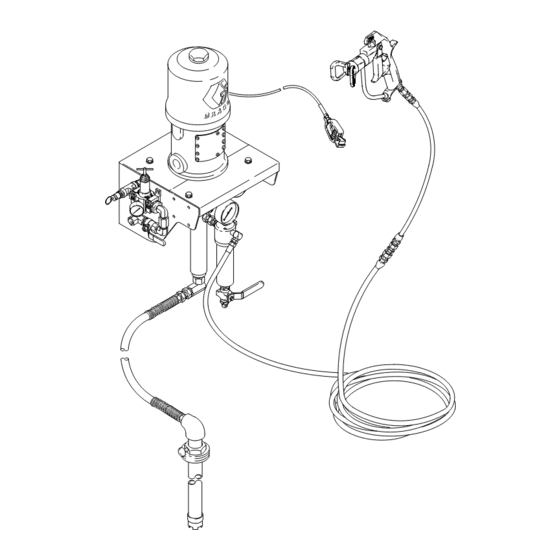
Model 232200 Shown
308756G
7
Advertisement

Subscribe to Our Youtube Channel
Related Manuals for Graco 232200


Summary of Contents for Graco 232200
- Page 1 Read all warnings and instructions in this manual. Save these instructions. See page 2 for model numbers and maximum working pressures. Model 232200 Shown GRACO INC. P.O. BOX 1441 MINNEAPOLIS, MN 55440–1441 Copyright 1997, Graco Inc. is registered to I.S. EN ISO 9001...
-
Page 2: Table Of Contents
........Graco Standard Warranty ..... . - Page 3 D This equipment is for professional use only. D Read all instruction manuals, tags, and labels before operating the equipment. D Use the equipment only for its intended purpose. If you are uncertain about usage, call your Graco distributor. D Do not alter or modify this equipment. Use only genuine Graco parts and accessories.
- Page 4 Permanently coupled hoses cannot be repaired; replace the entire hose. D Use only Graco approved hoses. Do not remove any spring guard that is used to help protect the hose from rupture caused by kinks or bends near the couplings.
- Page 5 WARNING FIRE AND EXPLOSION HAZARD Improper grounding, poor ventilation, open flames or sparks can cause a hazardous condition and result in a fire or explosion and serious injury. D Ground the equipment and the object being sprayed. Refer to Grounding on page 10. D If there is any static sparking or you feel an electric shock while using this equipment, stop spray- ing immediately.
- Page 6 Notes 308756...
- Page 7 Ensure that the wall is strong enough to support the parts drawing. weight of the pump and accessories, fluid, hoses, and NOTE: Always use Genuine Graco Parts and Acces- stress caused during pump operation. sories, available from your Graco distributor. Refer to Product Data Sheet 305900.
- Page 8 Installation D The airless spray gun (106) dispenses the fluid. Supplied Components The gun houses the spray tip (107), which is Refer to Fig. 1. available in a wide range of sizes for different spray patterns and rates of flow. WARNING D The fluid hose (101) and whip hose (103) supply fluid to the gun.
- Page 9 Air Relief Valve Air Inlet Swivel Included in Air Regulation Kit (16). Model 232200 Shown Mount the pump assembly so the top of the bracket is 4 to 5 ft (1.2 to 1.5 m) above the floor. The suction hose is 6 ft (1.8 m) long. Do not stretch the hose tight;...
- Page 10 Installation Grounding 2. Air and fluid hoses: use only electrically conductive hoses. WARNING 3. Air compressor: follow manufacturer’s recommen- FIRE AND EXPLOSION HAZARD dations. Before operating the pump, ground the system as explained below. Also read the section FIRE AND EXPLOSION HAZARD on page 5.
- Page 11 Operation Pressure Relief Procedure Packing Nut Before starting, fill the packing nut (M) 1/3 full with WARNING Graco Throat Seal Liquid (TSL) or compatible solvent. See Fig. 3. SKIN INJECTION HAZARD The system pressure must be manually WARNING relieved to prevent the system from starting or spraying accidentally.
- Page 12 Operation Prime the Pump (continued) WARNING 8. Hold a metal part of the gun (106) firmly to the side COMPONENT RUPTURE HAZARD of a grounded metal pail and hold the trigger open. To reduce the risk of overpressurizing your package, which could cause com- ponent rupture and serious injury, never 9.
- Page 13 106 Airless Spray Gun Packing Nut/Wet-Cup (hidden) Electrically Conductive Air Supply Hose Model 232200 Shown Torque as specified in your separate pump manual. The suction hose is 6 ft (1.8 m) long. Do not stretch the hose tight; let it hang as shown, to assist fluid flow into the pump.
- Page 14 Notes 308756...
- Page 15 Maintenance Preventive Maintenance Schedule Flush with a fluid that is compatible with the fluid you are pumping and with the wetted parts in your system. The operating conditions of your particular system Check with your fluid manufacturer or supplier for determine how often maintenance is required.
- Page 16 Parts Model 232200 Shown This style suction tube used on stainless steel models. Included in Suction Tube Kit 206266, used on carbon steel models. 21 (Ref) 101 (Ref) 7777 308756...
- Page 17 Parts Part No. 232200, Series A, 30:1 President, carbon steel (shown) Part No. 232201, Series A, 30:1 President, carbon steel, without hose and gun Part No. 232211, Series A, 30:1 President, stainless steel Part No. 232212, Series A, 30:1 President, stainless steel, without hose and gun Part No.
- Page 18 Parts Part No. 232200, Series A, 30:1 President, carbon steel (shown) Part No. 232201, Series A, 30:1 President, carbon steel, without hose and gun Part No. 232211, Series A, 30:1 President, stainless steel Part No. 232212, Series A, 30:1 President, stainless steel, without hose and gun Part No.
- Page 19 Hose and Gun Parts Part No. 232200, Series A, 30:1 President, carbon steel (shown) Part No. 232211, Series A, 30:1 President, stainless steel Part No. 232222, Series A, 23:1 Monark, carbon steel Part No. 232233, Series A, 23:1 Monark, stainless steel Part No.
-
Page 20: Technical Data
Category Data Maximum fluid Part Nos. 232200, 232201, 232211, 232212: 3000 psi (21 MPa, 210 bar) working pressure Part Nos. 232222, 232223, 232233, 232234: 2300 psi (16 MPa, 160 bar) Part Nos. 232263, 232264: 4600 psi (32 MPa, 317 bar) Maximum air input 100 psi (0.7 MPa, 7 bar) - Page 21 Technical Data Performance Charts To find Fluid Outlet Pressure (psi/MPa/bar) at a specific fluid flow To find Pump Air Consumption (m#/min or scfm) at a specific fluid (lpm/gpm) and operating air pressure (psi/MPa/bar): flow (lpm/gpm) and air pressure (psi/MPa/bar): 1. Locate desired flow along bottom of chart. 1.
-
Page 22: Dimensions
Dimensions Model 232200 Shown Mount the pump assembly so the top of the bracket is 4 to 5 ft (1.2 to 1.5 m) above the floor. 7779B Pump Model 232200/201 President 30:1 32 in. (813 mm) 17 in. (432 mm) 36 in. -
Page 23: Mounting Hole Layout
Mounting Hole Layout Check that the bracket is level before bolting it to the wall. Mount the pump assembly so the top of the bracket (1) is 4 to 5 ft (1.2 to 1.5 m) above the floor. 1.0 in. (25.4 mm) 5.0 in. -
Page 24: Graco Standard Warranty
With the exception of any special, extended, or limited warranty published by Graco, Graco will, for a period of twelve months from the date of sale, repair or replace any part of the equipment determined by Graco to be defective.
Need help?
Do you have a question about the 232200 and is the answer not in the manual?
Questions and answers