Table of Contents
Advertisement
Quick Links
Advertisement
Table of Contents

Related Manuals for Comelit 40863


Summary of Contents for Comelit 40863
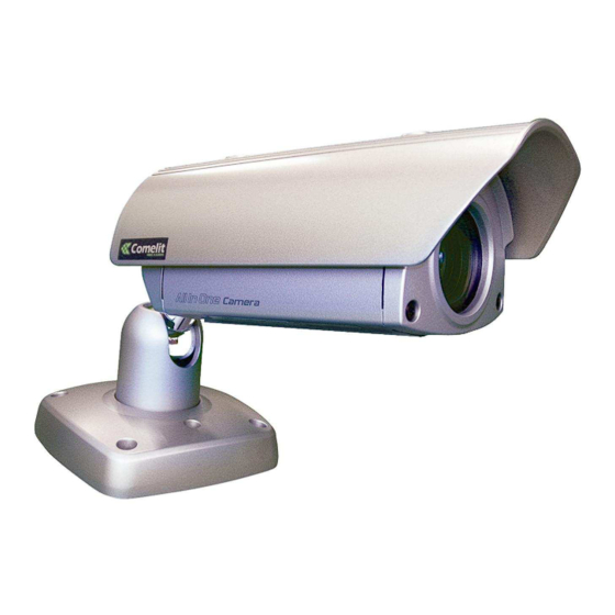
- Page 1 COLOR CCD WEATHERPROOF, AUTOFOCUS, DAY & NIGHT, ZOOM, ALL-IN-ONE CAMERA ART.40863 Please read this manual thoroughly before use and keep it for future reference. Via Don Arrigoni, 5 24020 Rovetta S. Lorenzo (Bergamo) http://www.comelit.it – E mail: export.department@comelit.it...
- Page 2 ISSUE 3 - OCTOBER 2007 LIMITATION OF LIABILITY THE INFORMATION IN THIS PUBLICATION IS BELIEVED TO BE ACCURATE IN ALL RESPECTS, HOWEVER, WE CANNOT ASSUME RESPONSIBILITY FOR ANY CONSEQUENCES RESULTING FROM THE USE THEREOF. THE INFORMATION CONTAINED HEREIN IS SUBJECT TO CHANGE WITHOUT NOTICE. REVISIONS OR NEW EDITIONS TO THIS PUBLICATION MAY BE ISSUED TO INCORPORATE SUCH CHANGES.
- Page 3 WARNINGS AND CAUTIONS: TO REDUCE THE RISK OF FIRE OR ELECTRIC SHOCK, DO NOT EXPOSE THIS PRODUCT TO RAIN OR MOISTURE. DO NOT INSERT ANY METALLIC OBJECTS THROUGH THE VENTILATION GRILLS OR OTHER OPENINGS ON THE EQUIPMENT. CAUTION: CAUTION CAUTION: TO REDUCE THE RISK OF ELECTRIC SHOCK, DO NOT REMOVE COVER(OR BACK).
- Page 4 FCC COMPLIANCE STATEMENT FCC INFORMATION : THIS EQUIPMENT HAS BEEN TESTED AND FOUND TO COMPLY WITH THE LIMITS FOR A CLASS A DIGITAL DEVICE, PURSUANT TO PART 15 OF THE FCC RULES. THESE LIMITS ARE DESIGNED TO PROVIDE REASONABLE PROTECTION AGAINST HARMFUL INTERFERENCE WHEN THE EQUIPMENT IS OPERATED IN A COMMERCIAL ENVIRONMENT.
- Page 5 IMPORTANT SAFEGUARDS 1. Read these instructions. 2. Keep these instructions. 3. Heed all warnings. 4. Follow all instructions. 5. Do not use this apparatus near water. 6. Clean only with dry cloth. 7. Do not block any ventilation openings. Install in accordance with the manufacturer's instructions.
- Page 6 THIS PAGE INTENTIONALLY LEFT BLANK. - 3 -...
-
Page 7: Table Of Contents
TABLE OF CONTENTS 1. INTRODUCTION 1.1 THE CAMERA FEATURES 2. SYSTEM INSTALLATION 2.1 PACKAGE CONTENTS 2.2 OPERATION REQUIREMENTS 3. PARTS NAME 3.1 INSTALLATIONS 4. CONNECTION 4.1 COLOR LEAD WIRE & COLOR DISPLAY LABEL 4.2 EXTERNAL DAY/NIGHT CONTROL 4.3 RS-485 CONNECTION 4.4 EXTERNAL LENS CONTROL 4.5 EXTERNAL A/D KEY CONTROL 5. -
Page 8: Introduction
Introduction The Day & Night AutoFocus Zoom color DSP Camera is designed especially for closed circuit television (CCTV) and security surveillance applications. 1.1 THE CAMERA FEATURES ALL-IN-ONE: Auto-focus camera / Lens / Weatherproof housing High performance SONY 1/4" Super HAD CCD 242x zooming capability (Optical : 22x / Digital : 11x) Ultra Sensitivity Minimum illumination of 0.001 lux @F1.6 (low shutter) Excellent picture quality... -
Page 9: System Installation
System Installation Installation of the camera must be performed by qualified service personnel in accordance with all local national electrical and mechanical codes. Perform the following steps to install the camera. 2.1 PACKAGE CONTENTS Camera Instruction Manual A/D Remote Controller (option) 2.2 OPERATION REQUIREMENTS <... -
Page 10: Parts Name
Parts Name Carefully remove the contents from the box, and verity that nothing was damaged in shipment. CAMERA CONTENTS SUNSHADE AF D&N CAMERA MODULE MOUNT BASE BIMETAL HEATER CONNECTION CABLE CABLE LABEL POLY BAG DRILLING GUIDE LABEL 4 Point - Drilling Position ACCESSORY KIT MOUNT TORX SCREWS(M6x35.0)(4X) 502016 23A... - Page 11 3.1.1 INSTALLATION 1 (Cable through the wall with the mount base) A. Drill the mounting location, using the template sheet (or the bottom of the mount base) as a template. B. Insert the plastic anchors into the hole which has just drilled. C.
- Page 12 3.1.2 INSTALLATION 2 (Using the conduit knockout punched with Mount Base) A. Drill the mounting location, using the template sheet (or the bottom of the mount base) as a template. B. Insert the plastic anchors into the hole which has just drilled. C.
- Page 13 3.1.3 INSTALLATION 3 (Cable through junction box with mount base) The camera can be mounted on the junction box using the UNC # 8-32 machine screws.
-
Page 14: Connection
Connection CAUTION : Do not connect the power cable until all other connections have been completed. If you complete the whole connection of cameras, then you have to cut the extra cable. 4.1 COLOR LEAD WIRE & COLOR DISPLAY LABEL... -
Page 15: External Day/Night Control
4.2 EXTERNAL DAY/NIGHT CONTROL Connect to an external sensor to receive day/night detection signals. External sensor switch ON/OFF DAY/NIGHT DAY : OPEN DAY/NIGHT (BLACK) NIGHT : CLOSED COLOR EXT-OUT EXT-IN (GRAY) EXT-OUT (WHT-BLK) COLOR *Note: To validate the sensor inputs, select Function menu B/W mode the EXT 4.3 RS-485 CONNECTION Connecting to the RS-485 : The Camera can be controlled remotely by an external device or control system, such as a control keyboard, using RS-485... -
Page 16: External A/D Key Control
4.5 EXTERNAL A/D KEY CONTROL External Controller Circuit Schematic A/D KEY ADKEY2 Remote Controller A/D KEY (ORANGE) A/D KEY (BLACK) (WHITE) MEN U TELE FA R NEA R WID E 42mm Remote Controller... -
Page 17: Camera Adjustment
Camera Adjustment 5.1 OSD MAIN SCREEN AF 22X AEAUTO NORMAL F1.6 84X CAM 01 Camera title. Status of the auto exposure. Status of the auto white balance. Status of the focus mode. Status of the zoom position, brightness, or sharpness. Status of the shutter speed. -
Page 18: Main Menu
5.2 MAIN MENU <MAIN MENU> TITLE DISPLAY/ALARM CAM SET EFFECT PRESET 5.2.1 WB (White Balance) <WB> INDOOR OUTDOOR MANUAL R/B WAWB Auto white balance mode. INDOOR Indoor white balance mode. OUTDOOR Outdoor white balance mode. MANUAL Manual mode. You can change R and B Gain manually. For changing R and B gain, use "NEAR"... - Page 19 5.2.2 AE (Auto Exposure) <WE> AUTO IRIS PRI SHUTTER PRI MANUAL IRIS SHUT LOWSHUT AUTO Auto exposure mode. (Iris, Shutter, AGC) IRIS PRI Iris priority auto exposure mode. SHUTTER PRI Shutter priority auto exposure mode. Auto gain control on/off. MANUAL Manual exposure mode.
- Page 20 5.2.4 TITLE TITLE <TITLE MENU> A. TITLE B. Character Table C. Command Line : Move to left : Move to right < : Erase a left character > : Erase a right character S : Save title E : End 5.2.5 DISPLAY/ALARM <DISPLAY/ALARM>...
- Page 21 5.2.6 CAM SET <CAM SET> BRIGHTNESS SHARPNESS DISTANCE MAX LOW SHUT PROTOCOL SAVE PROTOCOL & BPS Select the camera ID. (1 ~ 255) Select serial communication speed. (2400 / 4800 / 9600 / 19200) BRIGHTNESS Select brightness level (0 ~ +90) Default value is 30.
- Page 22 5.2.7 EFFECT <EFFECT> D-ZOOM NEGA/POSI MIRROR FREEZE D-ZOOM Digital Zoom on/off. NEGA/POGI Select the Negative or Positive picture. Select Color & B/W picture or EXT mode. MIRROR Select horizontal reverse picture. Picture In picture on/off. FREEZE Select real and still picture. Day &...
- Page 23 5.2.8 PRESET <PRESET> FOCUS SYNC INIT LOAD SAVE SHOT ZOOM PRESET SET ZOOM PRESET FOCUS Select auto, manual, pushauto mode. SYNC Select internal or line lock mode. Sync phase is adjustable in line lock mode. INIT Camera initialize mode selection(DEFAULT / PRESET). LOAD Load default or preset parameters of camera (DEFAULT / PRESET).
- Page 24 THIS PAGE INTENTIONALLY LEFT BLANK.
-
Page 25: Troubleshooting And Maintenance
Troubleshooting and Maintenance 6.1 TROUBLESHOOTING If problems occur, verify the installation of the camera with the instruction in this manual and with other operating equipment. Isolate the problem to the specific piece of equipment in the system and refer to the equipment manual for further information. -
Page 26: Specifications
Specifications MODEL NTSC Power Source AC 24V / DC 12V (Dual Power) POWER Power Consumption 9.0 Watts Image Sensor 1/4" SONY Super HAD CCD 811(H) x 508(V) 795(H) x 596(V) Total Pixels Scanning System 2:1 interlace Scanning Frequency 15,734KHz(H), 59,94Hz(V) 15,625KHz(H), 50Hz(V) Sync. -
Page 27: Dimensions
Dimensions 86mm 4- 6.4 SC HOLES 85mm 120mm 120mm < FRONT VIEW > < REAR VIEW > 308mm 218mm 271mm < SIDE VIEW >... - Page 28 Via Don Arrigoni, 5 24020 Rovetta S. Lorenzo (Bergamo) http://www.comelit.it – E mail: export.department@comelit.it 50302061D...
Need help?
Do you have a question about the 40863 and is the answer not in the manual?
Questions and answers