Table of Contents
Advertisement
Quick Links
Advertisement
Table of Contents

Related Manuals for Comelit DOME CAMERA


Summary of Contents for Comelit DOME CAMERA
- Page 1 ¼” SONY SUPER HAD/EX-VIEW CCD COLOR DAY & NIGHT “ALL-IN-ONE” DOME CAMERA ART. 40799-40800 Please read this manual thoroughly before use and keep it for future reference. Via Don Arrigoni, 5 24020 Rovetta S. Lorenzo (Bergamo) http://www.comelit.it – E mail:...
-
Page 2: Warnings And Cautions
Warnings and Cautions WARNING TO REDUCE THE RISK OF FIRE OR ELECTRIC SHOCK, DO NOT EXPOSE THIS PRODUCT TO RAIN OR MOISTURE. DO NOT INSERT ANY METALLIC OBJECTS THROUGH THE VENTILATION GRILLS OR OTHER OPENINGS ON THE EQUIPMENT. CAUTION EXPLANATION OF GRAPHICAL SYMBOLS The lightning flash with arrowhead symbol, within an equilateral triangle, is intended to alert the user to the presence of uninsulated "dangerous voltage"... -
Page 3: Fcc Compliance Statement
FCC COMPLIANCE STATEMENT FCC INFORMATION: THIS EQUIPMENT HAS BEEN TESTED AND FOUND TO COMPLY WITH THE LIMITS FOR A CLASS A DIGITAL DEVICE, PURSUANT TO PART 15 OF THE FCC RULES. THESE LIMITS ARE DESIGNED TO PROVIDE REASONABLE PROTECTION AGAINST HARMFUL INTERFERENCE WHEN THE EQUIPMENT IS OPERATED IN A COMMERCIAL ENVIRONMENT. -
Page 4: Important Safeguards
IMPORTANT SAFEGUARDS 1. Read these instructions. 2. Keep these instructions. 3. Heed all warnings. 4. Follow all instructions. 5. Do not use this apparatus near water. 6. Clean only with dry cloth. 7. Do not block any ventilation openings. Install in accordance with the manufacturer's instructions. -
Page 5: Table Of Contents
2.1 Package Contents..........................3 2.2 Installation ............................3 2.3 Basic Configuration of Dome Camera System ..................4 2.4 Setting Dome Camera Termination and Fail Safe Bias ...............6 2.5 Setting Dome Camera Address (ID) ....................6 2.6 Setting Dome Camera Protocol ......................7 2.7 Connections ............................8 2.8 Getting Started ...........................10... - Page 6 3.13 Camera –22X MODEL.........................25 Focus Control ............................25 WB (White Balance) Control ........................26 AE Control ............................26 Line Lock Control ..........................27 Night Shot Menu...........................27 3.14 Dome Setup............................28 Language Setup ...........................28 Home Function Setup...........................28 OSD Display ............................29 View Direction ............................29 Dome OSD Display ..........................29 Area Display ............................29 View Angle Setup ..........................30 Panning Range.............................30...
-
Page 7: Chapter 1 - Introduction
Chapter 1 — Introduction 1.1 Features The dome camera and the Keyboard Controller make up the building blocks for any surveillance/security system. Using multiple Keyboard Controllers and multiple dome cameras, no place is too large for monitoring. Extensible and flexible architecture facilitates remote control functions for a variety of external switching devices such as multiplexers and DVRs. - Page 8 Figure 1 – Typical System Configuration...
-
Page 9: Chapter 2 - Installation And Configuration
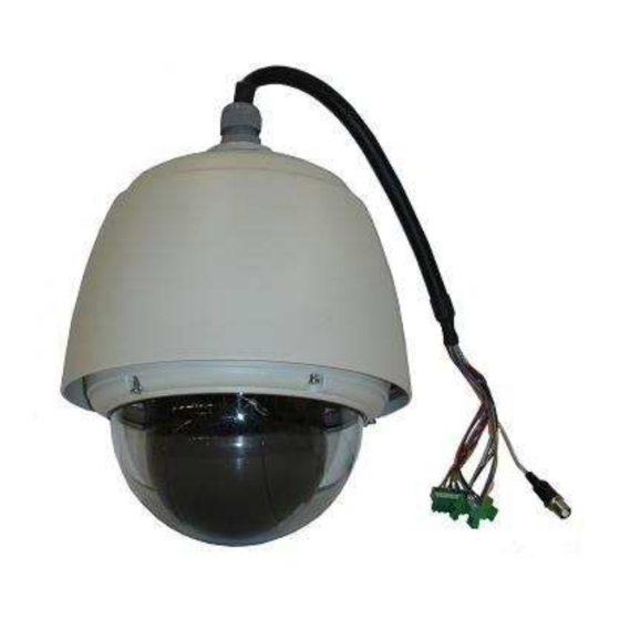
Chapter 2 — Installation and Configuration 2.1 Package Contents AIO (All In One) is design to a compact, small size, hard Dome Camera Housing. The housing is constructed of aluminum, steel and plastic. The housing is designed to be mounted both wall and ceiling type. -
Page 10: Basic Configuration Of Dome Camera System
2.3 Basic Configuration of Dome Camera System Figure 2 – Basic Installation Diagram The dome camera must be installed by qualified service personnel in accordance with all local and federal electrical and building codes. - Page 11 Figure 3 – Layout of Switches...
-
Page 12: Setting Dome Camera Termination And Fail Safe Bias
MUX x No. of camera IN. (e.g. multiplexer ID= n, Camera IN= m then ID of Dome =16x(n-1)+m ) Figure 5 – Setting Dome Camera Address (ID) When you set the dome camera address (ID) over 99, press 2 , 5 , 0 , and PRST keys of the keyboard. Then the FACTORY SETUP displays as below. -
Page 13: Setting Dome Camera Protocol
ANSWER DELAY means the response time of the dome and you don’t need to change in normal condition. 2.6 Setting Dome Camera Protocol If a dome camera is to be installed with a Fastrax keyboard controller, select F2E protocol. Consult service personnel if a dome camera is installed with device other than a keyboard controller. -
Page 14: Connections
Use certified / Listed Class 2 power supply transformer only. • Connecting to the RS485 The dome camera can be controlled remotely by an external device or control system, such as a control keyboard, using RS485 half-duplex serial communications signals. Connect Marked R+, R- to Tx+ and Tx- of the RS485 control system. - Page 15 CONNECTOR 1 : AC+ / AC- /G /R- /R+/G CONNECTOR 2 : F+ / F- COLOR DESCRIPTION COLOR DESCRIPTION AC+: BLACK F+: AC 24V (HEATER & FAN) AC 24V AC-: ORANGE AC 24V BROWN F-:AC 24V (HEATER & FAN) YELLOW G:GND GREEN GRAY...
-
Page 16: Getting Started
2.8 Getting Started Once installed apply power to the dome camera. The dome camera will start a configuration sequence. When configuration is done, the following information is displayed on the monitor. FASTRAX IIL Vx.xxx CAMERA TYPE xxxx WAIT DOME SETTING. -
Page 17: Chapter 3 - Program And Operation
Chapter 3 — Program and Operation 3.1 Dome Camera Selection Before you program or operate a dome camera, you must select the dome camera by pressing the dome camera No. + CAM Example: Pressing 1 , 0 and CAM key sequentially will select dome camera 10. The selected dome camera ID will be displayed on the LCD monitor of the keyboard controller. -
Page 18: How To Control On-Screen Menu Utility
3.3 How to control the On-Screen Menu Utility Action Function MENU Call the On-screen menu utility Go into the sub-menu items. Execute the command (exit) Joystick left or right Change value. Navigate through the menu items. Joystick up or down Navigate through the menu items. - Page 19 1. Press the SCAN key to enter Auto Scan menu directly. Or press the MENU key to display the main menu on the monitor. Scroll to Auto Scan and push the Joystick to the right. 2. Select an Auto Scan number by pushing the Joystick left or right. 3.
-
Page 20: Preset
Preset button on your controller automatically calls up the preset. In addition, presets may be assigned to alarm actions or as the “home” position for the dome camera. As many as 128 presets, whose positions are saved in the dome’s memory, may be programmed. -
Page 21: Shortcut Preset Program
7. When you are finished entering the title, push the Joystick downward. Set the focus by pushing the Joystick to the right or left. Set the IRIS value in the same manner as the focus. 8. Move to the DWELL setting by pushing the Joystick down. Twist the Joystick clockwise or counterclockwise to increase or decrease dwell time of the preset position. - Page 22 TOUR 01:xxxxxxxxxxxxxxxx SCAN TYPE:NORMAL === === 003 === === === === A04 === === === === === === === T02 === 001 === === === === === === T04 === === === === === === === === === === SAVE AND EXIT(ESC TO CANCEL) PRESS FUNCTION KEY AND ROTATE JOYSTICK TO SELECT NUMBER.
-
Page 23: Pattern
(Fourth 4 Item of the Main menu / Shortcut: PTRN) The Pattern feature records user control of the selected dome camera for up to 60 seconds. Two patterns can be stored and played back by pressing 1 or 2 + PTRN keys subsequently. -
Page 24: Alarm
3.9 Alarm (This menu shows on only specific model, Fifth Item of Main menu) ALARM SETUP NO PRI PRS IN OUT HLD LATCH 001 OFF OFF A01 OFF OUT1 3 080 NO OUT1 3 001 NC OUT1 3 SAVE AND EXIT(ESC TO CANCEL) : Alarm input number PRIO : Lower No. -
Page 25: Area Title
3.10 Area Title (Sixth Item of Main menu) Enter a specific name on programmed angle between START and END. For the screen below, when the camera points at an angle between 124.3° to 359.5°, ABC will be displayed on the screen. -
Page 26: Privacy Zone
3.11 Privacy Zone (Seventh Item of Main menu) Hide up to 8 unwanted views in a camera. PRIVACY ZONE SETUP TITLE METHOD 01 xxxxxxxxxxxxxxxx BLOCK 02 xxxxxxxxxxxxxxxx V.OFF 03 xxxxxxxxxxxxxxxx NONE ==== 04 xxxxxxxxxxxxxxxx NONE ==== 05 xxxxxxxxxxxxxxxx NONE ==== 06 xxxxxxxxxxxxxxxx NONE ==== 07 xxxxxxxxxxxxxxxx... -
Page 27: Camera -26X Model
3.12 Camera – ART. 40799 (Eighth Item of Main menu) CAMERA SETUP FOCUS CONTROL WB CONTROL AE CONTROL LINE LOCK CONTROL SHARPNESS BACK LIGHT : OFF DIGITAL ZOOM : OFF (2X/4X/MAX) NIGHT SHOT CONTROL SAVE AND EXIT(ESC TO CANCEL) SHARPNESS The higher the value,the more edges in the picture will be enhanced (0~15) BACK LIGHT Objects in front of bright backgrounds will be clearer with BLC ON. -
Page 28: Wb (White Balance) Control
• WB (White Balance) CONTROL WB SETUP MODE AUTO R GAIN : B GAIN : EXIT(ESC TO EXIT) MODE: MANUAL / AUTO / INDOOR / OUTDOOR / ONE PUSH / ATW R GAIN: 0 ~ 255 B GAIN: 0 ~ 255 Use the ATW mode for normal use. -
Page 29: Line Lock Control
• LINE LOCK CONTROL LINE LOCK SETUP MODE INTERNAL PHASE EXIT(ESC TO EXIT) MODE: INTERNAL / EXTERNAL Adjusts phase of picture with other PHASE: 0~255 cameras in EXTERNAL mode. EXIT (ESC TO EXIT) • NIGHT SHOT MENU The NIGHT SHOT option removes the IR cutoff filter of the camera and makes the camera sensitive to near infrared. - Page 30 Eclipse of the Lens: The eclipse phenomenon occurs with this model. This is because a sufficient amount of aperture is not available due to the CCD size and the lens structure of this model. However, it has been verified that the eclipse will not be visible in the case of a more than 90% effective image. For your reference, see the following diagram.
-
Page 31: Camera -22X Model
3.13 Camera – ART. 40800 (Eighth Item of Main menu) CAMERA SETUP FOCUS CONTROL WB CONTROL AE CONTROL LINE LOCK CONTROL SHARPNESS : 10 BACK LIGHT : OFF DIGITAL ZOOM : OFF (MAX) NIGHT SHOT CONTROL SAVE AND EXIT(ESC TO CANCEL) SHARPNESS The higher the value, the more edges in the picture will be enhanced User can adjust sharpness level from 0 to 20. -
Page 32: Wb (White Balance) Control
• WB (White Balance) CONTROL WB SETUP MODE R GAIN : B GAIN : EXIT(ESC TO EXIT) MODE: AWB / WAWB / INDOOR / DOUDOOR / MANUAL WAWB: Wide range auto white balance mode. R GAIN: 0 ~ 255 B GAIN: 0 ~ 255 Use the AWB mode for normal use. -
Page 33: Line Lock Control
• LINE LOCK CONTROL LINE LOCK SETUP MODE INTERNAL PHASE : EXIT(ESC TO EXIT) INTERNAL / EXTERNAL MODE: Adjusts phase of picture with other PHASE: 0~255 cameras in EXTERNAL mode. EXIT (ESC TO EXIT) • NIGHT SHOT MENU The NIGHT SHOT option removes the IR cutoff filter of the camera and makes the camera sensitive to near infrared. -
Page 34: Dome Setup
3.14 Dome Setup (Ninth Item of Main menu) CONFIGURATION MENU LANGUAGE SETUP HOME FUNCTION SETUP OSD DISPLAY VIEW ANGLE SETUP INITIALIZE DATA ORIGIN OFFSET DOME RESET SYSTEM INFORMATION EXIT(ESC TO EXIT) • LANGUAGE SETUP LANGUAGE SETUP LANGUAGE : ENGLISH SAVE AND EXIT(ESC TO CANCEL) LANGUAGE: Select the language you want. -
Page 35: Osd Display
If this option is enabled, the nearest area title will be displayed when the camera is moving whether by manual operation, Auto Scan, or Pattern. Select ON or OFF by pushing the Joystick to the right or to the left. The Dome camera’s OSD will override this function (Dome camera’s OSD must be enabled). -
Page 36: View Angle Setup
(wide angle). ON: In some installations it is desirable for the dome camera to be able to see above the horizon. When this option is chosen, the dome will tilt up over the horizon (About -10 degrees). -
Page 37: Initialize Data
ERASE PROGRAMMED DATA EXIT(ESC TO EXIT) Erase all stored data from the Flash-ROM of the selected dome camera. You will be asked to enter Yes or No. If you intend to erase all data then press the MENU key, otherwise press the ESC key to exit without erasing. -
Page 38: Appendix A - Specifications
Appendix A — Specifications Camera art. 40800 Image Sensor 1/4" Super-HAD Color CCD NTSC : 768 x 494 Approx. 380K pixels Picture elements : 752 x 582 Approx. 440K pixels Horizontal Resolution 480 / 470 lines (NTSC / PAL) 22x optical zoom with auto focus Lens 11x digital zoom F1.6 to F3.6, f=3.9mm to 85.8mm... - Page 39 General Certification CE EMC, FCC CLASS A, CSA, IP66 Electrical Power Requirement 24VAC 1A for dome 24VAC 2.2A for heater and fan Power Consumption Maximum 20W for dome Maximum 50W for heater Maximum 2.4W for fan Alarm Output 1 Normal relays 24VDC/1A Max. (selectable NC/NO) Alarm Input 4 Normal dry contact (selectable NC/NO) Control...
- Page 40 Figure 6 – Dimensions...
-
Page 41: Appendix B - Troubleshooting
Check the video connections Check that the BNC connectors are inserted properly. Poor video quality. Check the voltage level of the dome camera. Cable for video is shielded. Reset the cameras using the Dome configuration Dome cameras lose their positions. -
Page 42: Appendix C - Glossary
The default position may be a Preset, Tour, Pattern, or No Action. Input Alarm A connection point on the dome camera that enables the system to monitor Input Devices. There are four inputs available for the dome camera. Input Devices External devices that provide information about the condition of system components that connect to the inputs on the dome camera. -
Page 43: Line Lock
Normal Input State Describes the expected state of a device connected to one of eight dome camera’s inputs. The normal state may be open or closed. When a device is not in its normal input state, an alarm is issued. -
Page 44: Privacy Zones
The Privacy Zones move in relation to the dome camera’s pan/tilt position. In addition, the apparent size of the Privacy Zone adjusts automatically as the lens zooms in or out. Up to eight Privacy Zones may be established for a dome camera. -
Page 45: Appendix D - Short Cut Key
Appendix D — Short Cut Key Short Cut Key Function PRST Pop up preset setup menu. TOUR Pop up guard Tour setup menu. PTRN Pop up Pattern setup menu. SCAN Pop up Auto Scan setup menu. NO.+ PGM +PRST Store the current view at the selected number. 1 + ON Turn On Relay. -
Page 46: Appendix E - Wall Mount
2. Mark and drill mounting holes in the surface using the Wall Mount Flange. 3. Pull out cables required to connect to the dome camera from the wall or route cables through a section of 0.75 in. (19mm) conduit pipe. -
Page 47: Appendix F - Ceiling Mount
2. Mark and drill mounting holes in the surface using the ceiling mount flange. 3. Pull out cables required to connect to the dome camera from the ceiling. 4. Attach the ceiling mount bracket using screws routing cables through the locking nut. - Page 48 Via Don Arrigoni, 5 24020 Rovetta S. Lorenzo (Bergamo) http://www.comelit.it – E mail: export.department@comelit.it...
Need help?
Do you have a question about the DOME CAMERA and is the answer not in the manual?
Questions and answers