
Related Manuals for Jasic CUT40HF


Summary of Contents for Jasic CUT40HF
- Page 1 CUT40HF/CUT40NHF CUT45PFC IGBT INVERTER CUTTER Copyright©2022 Shenzhen JASIC Technology Co., Ltd.
- Page 2 Manual. 2. JASIC reserves the right to amend this Manual at any time without prior notice. 3. Although the contents of this Manual have been carefully checked, there may still be inaccuracies. If users find out, please consult with our company.
-
Page 3: Table Of Contents
Appendix 1: Wiring diagram of CUT45PFC.................. 27 Appendix 2: Exploded-view drawing of CUT45PFC..............28 Appendix 3: List of CUT45PFC common spare parts..............29 Appendix 4: Wiring diagram of CUT40HF/CUT40NHF...............30 Appendix 5: Exploded-view drawing of CUT40HF/CUT40NHF..........31 Appendix 6: List of CUT40HF/CUT40NHF common spare parts..........32 Page 3... - Page 4 For your safety, please read this manual carefully before installing and operating this JASIC equipment. Pay extra attention to all content marked with " ". All operations must be carried out by professional, suitably qualified persons! Page 4...
-
Page 5: Safety Precautions
1. Safety precautions 1.1. General safety SAFETY INSTRUCTION These general safety norms cover both arc welding machines and plasma cutting machines unless otherwise noted. It is important that users of this equipment protect yourselves and others from harm or even death. - Page 6 Arc rays——May injure the eyes and burn the skin. The arc rays from all processes produce intense, visible and invisible (ultraviolet and infrared) rays that can burn eyes and skin. ·Wear an approved welding helmet fitted with an appropriate shade of filter lens to protect your face and eyes when working or watching.
- Page 7 5 minutes after power switch off before removing the panels. If you still do not fully understand or cannot solve the problem after reading the instructions in this manual, you should contact the supplier or JASIC's service center immediately for professional help.
-
Page 8: Other Precautions
1.2. Other precautions Warning! Location The machine should be located in a suitable position and environment. Care should be taken to avoid moisture, dust, steam, oil or corrosive gases. Place on a secure level surface and ensure that there is adequate clearance around the machine to ensure natural airflow. -
Page 9: Description Of Symbols
2. Description of symbols Warning! Read the Manual Electric shock risk warning WEEE tag Current unit "A" Overheat protection indicator Overcurrent protection indicator 2T continuous cut 4T continuous cut Mesh cutting Home Return Encoder Page 9... -
Page 10: Product Overview
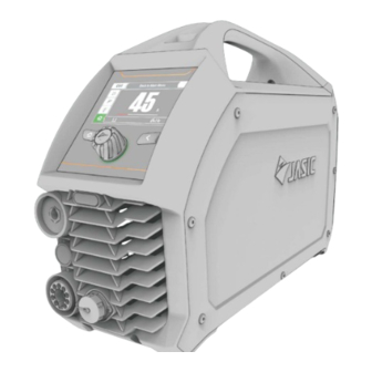
3. Product overview This is a digital inverter air plasma cutter featuring advanced technology with excellent performance. It provides a stable DC arc and can cut carbon steel, low alloy steel, stainless steel and other materials. Moreover, it offers adjustable cutting torch length setting and post flow time setting. -
Page 11: Technical Parameters
4. Technical parameters Item Unit Parameters Model CUT45PFC CUT40HF CUT40NHF Input voltage AC95~265V AC230V±15% AC230V±15% Input frequency 50/60 50/60 50/60 Rated input current (AC230V) Rated input current (AC115V) Rated input power (AC230V) Rated input power (AC115V) Output current range 20~45 20~40... -
Page 12: Installation
5. Installation Warning! All connections shall be made with the power supply is turned off. Warning! Electric shock may cause death; after power failure, there is still a high voltage on the equipment, do not touch the live parts on the equipment. Warning! Incorrect input voltage may damage the equipment. -
Page 13: Power Installation
5.2. Power installation Warning! The electrical connection of equipment shall be carried out by suitably qualified personnel. Warning! All connections shall be made after the power supply is off. Warning! Incorrect voltage may damage the equipment. 1) Ensure the input voltage value is within the specified input voltage range. 2) Ensure that the power switch of the cutter is turned off. -
Page 14: Connection Of Cutting Torch, Earth Cable And Gas Hose
5.3. Connection of cutting torch, earth cable and gas hose 1) Ensure that the power switch of the cutting machine is turned off. 2) Insert the cable plug with earth clamp into the corresponding positive fast socket on the front panel of the machine and tighten it clockwise. 3) Insert the central plasma plug of the cutting torch into the negative central plasma socket on the front panel of the machine and tighten it clockwise. -
Page 15: Control Panel
6. Control panel 6.1. Overview a. Home: return to Home page b. Return: return to upper level c. Confirm: go to next level d. Function adjustment knob: adjust the parameter or focal spot e. LCD screen: display information 6.2. Display of parameters and error codes 1) Display the current configuration, operation mode, post-flow time, and information prompt on current operation. -
Page 16: Parameter Adjustment Knob
2) When the factory settings are restored, a prompt window is displayed. 3) When the barcode queried, the machine barcode is displayed. 4) When the product is not working correctly, an error code is displayed. 6.3. Parameter adjustment knob 1) Parameter adjustment: When adjusting the parameter, the focal spot is cancelled. Rotate the knob to adjust the parameter. -
Page 17: Selection Of Working Mode
6.4. Button operation 1) Home: After pressing Home, the screen jumps to the Home page. 2) Confirm: After pressing Confirm, the current focal spot response operation is performed. 3) Return: After pressing Return, the screen returns to the upper-level menu. 6.5. -
Page 18: Cutting Current Configuration
6.7. Cutting current configuration In the Continuous Cut or Mesh Cut page, the display window shows the current cutting current. Enter the adjusted current by rotating the knob. 6.8. 2T/4T function settings In the Continuous Cut page, enter the Function Settings menu to select 2T or 4T. 、... -
Page 19: Help
6.10. Help In the Settings page, enter the Help menu to display the current machine information. 、 6.11. Language selection In settings page, enter the Language Selection menu to select English or Simplified Chinese. 、 6.12. Unit configuration In the Settings page, enter the Unit Setting menu to select the Imperial or metric system. 、... -
Page 20: User Manual
、 、 Parameter Reset: restore all cutting parameters of the machine. 、 、 Factory Reset: Restore all factory settings of the machine. 、 、 6.14. User manual In the Home page, enter the User Manual to select Operation, Components, or Maintenance. -
Page 21: Protective Indication
、 6.15. Protective indication If the page displays , it indicates that the cutting machine has entered protected state and stopped output. 7. Cutting function operation 7.1. Cutting operation 7.1.1 Turn on the power switch. The power switch is located at the rear panel of the machine; set it in the "ON" position; then the panel indicator will light up, the fan will start to rotate, and the machine will start to work normally. - Page 22 the encoder to adjust the current parameter. NOTE! The operator should set the functions that meet the cutting requirements. If the selections are incorrect, this may lead to problems such as an unstable arc, incomplete cutting, more dross, rough cutting surface and heavy consumables consumption and etc.
-
Page 23: Maintenance
8. Maintenance Warning! The following operation requires sufficient professional knowledge on electric aspects and comprehensive safety knowledge. Make sure the input cable of the machine is disconnected from the electricity supply and wait for 5 minutes before removing the machine covers. Please note: The following should only be carried out by an authorised electrical technician. -
Page 24: Troubleshooting
9. Troubleshooting Warning! Before machines are dispatched from the factory, they have already been checked thoroughly. The machine should not be tampered with or altered. Maintenance must be carried out carefully. If any wire becomes loose or is misplaced, it maybe potentially dangerous to user! Only professional maintenance personnel should repair the machine! Ensure the power is disconnected before working on the machine. -
Page 25: Alarms And Solutions
·The cutting current and cutting ·Choose the correct cutting speed do not match the thickness standard operation - refer to section of the workpiece 7.1.3 "Cutting Procedure Checklist" Poor cutting ·The cutting air pressure is too low ·Ensure that the working air quality or high pressure range is 0.35-0.55MPa... -
Page 26: Packaging, Transportation, Storage And Waste Disposal
10. Packaging, transportation, storage and waste disposal 10.1. Transportation requirements In the process of handling the equipment, it should be handled with care, and should not be dropped or severely impacted. Avoid moisture and rain during transportation. 10.2. Storage conditions Storage temperature:-25 ℃... -
Page 27: Appendix 1: Wiring Diagram Of Cut45Pfc
Appendix 1: Wiring diagram of CUT45PFC Page 27... -
Page 28: Appendix 2: Exploded-View Drawing Of Cut45Pfc
Appendix 2: Exploded-view drawing of CUT45PFC Page 28... -
Page 29: Appendix 3: List Of Cut45Pfc Common Spare Parts
Appendix 3: List of CUT45PFC common spare parts Material Name Quantity Material Name Quantity code code Right side Handle 51001788 51001965 cover Top cover Rocker switch 51001964 51000471 Rear bracket Ring 51001677 10083802 Rear panel 51001808 51000336 Regulator HF board 51001972 51000501 mount... -
Page 30: Appendix 4: Wiring Diagram Of Cut40Hf/Cut40Nhf
Appendix 4: Wiring diagram of CUT40HF/CUT40NHF Page 30... -
Page 31: Appendix 5: Exploded-View Drawing Of Cut40Hf/Cut40Nhf
Appendix 5: Exploded-view drawing of CUT40HF/CUT40NHF Page 31... -
Page 32: Appendix 6: List Of Cut40Hf/Cut40Nhf Common Spare Parts
Appendix 6: List of CUT40HF/CUT40NHF common spare parts Material Name Quantity Material Name Quantity code code 51001788 Handle 51001899 Chassis 51001964 Top cover 51001679 Right mount Right side 51001677 Rear bracket 51001965 cover 51001808 Rear panel 51000471 Rocker switch Regulator... - Page 33 Page 33...
Need help?
Do you have a question about the CUT40HF and is the answer not in the manual?
Questions and answers