Table of Contents
Advertisement
Quick Links
Instructions
GLC X Lubrication
Controller
For controlling and monitoring an automated lubrication system. For professional use
only.
Not approved for use in explosive atmospheres or hazardous (classified) locations.
Model: 26A814
Important Safety Instructions
Read all warnings and instructions in this
manual and in the pump manual before
using the equipment. Save these
instructions.
3A7031A
EN
Advertisement
Table of Contents

Related Manuals for Graco 26A814


Summary of Contents for Graco 26A814
- Page 1 For controlling and monitoring an automated lubrication system. For professional use only. Not approved for use in explosive atmospheres or hazardous (classified) locations. Model: 26A814 Important Safety Instructions Read all warnings and instructions in this manual and in the pump manual before using the equipment.
-
Page 2: Table Of Contents
California Proposition 65 ....25 Graco Standard Warranty ....26... -
Page 3: Warnings
Warnings Warnings The following warnings are for the set up, use, grounding, maintenance, and repair of this equipment. The exclamation point symbol alerts you to a general warning and the hazard symbols refer to procedure-specific risks. When these symbols appear in the body of this manual or on warning labels, refer back to these Warnings. Product-specific hazard symbols and warnings not covered in this section may appear throughout the body of this manual where applicable. -
Page 4: Component Identification
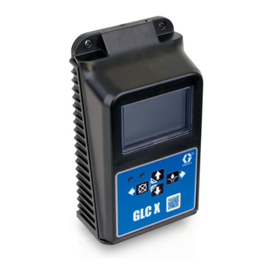
Component Identification Component Identification (A) System LED NOTICE To prevent damage to soft key buttons, do not press Light Status the buttons with sharp objects such as pens, plastic Red (solid) Normal and ON cards, screwdrivers, or fingernails. Orange (solid) Controller is in system SETUP and lubrication program is paused Red (flashing) - Page 5 Component Identification Identification Label . 2: GLC X Controller Back 3A7031A...
-
Page 6: Typical Installation
Typical Installation Typical Installation The installation shown in F . 3 is only a guide for selecting and installing system components. . 3: Typical Installation Key: Lubrication Controller Solenoid Value Pump Module Ignition Switch High Pressure Lubricant Supply Lines Injector Banks In-line 15A Fuse Power Source Pressure Sensor... -
Page 7: Installation
Installation Installation Wiring The Lubrication Controller Connector (H) is rated for 240 VAC, 17 A (F . 5). AUTOMATIC SYSTEM ACTIVATION HAZARD Unexpected activation of the pump lubrication system could result in serious injury, including skin injection and amputation. The Lubrication Controller has an automatic timer that activates the pump lubrication system when power is connected or when exiting this device’s programming function. -
Page 8: System Configuration
System Configuration System Configuration To determine the required configurations needed, refer to the following pages. Injector System . 6 Injector System Configuration 3A7031A... -
Page 9: Divider Valve
System Configuration Divider Valve . 7 Divider Valve System Configuration 3A7031A... -
Page 10: Wiring Diagram
System Configuration Wiring Diagram . 8: Wiring Diagram Wiring Key Description Polarity Pump / Motor Auxiliary / Alarm Auxiliary / Alarm ground Sensor power 1 Sensor power 2 Voltage source Pump / Motor ground Input 2 ground Input 2 (LOW LEVEL) Input Voltage source ground Input 3 (CYCLE) -
Page 11: Sensor Wiring Configurations
Sensor Wiring Configurations Sensor Wiring Configurations Dry Contact Switch Source/PNP Switch (2 or 3 Wire Type) Analog Sensor . 11 . 10 3A7031A... -
Page 12: Setup
Setup Setup Navigating Setup and Data Entry Interval UP and DOWN Arrows: Configures how frequently the GLC X lubricates the • Press both the UP and DOWN Arrows product. simultaneously for 3 seconds to enter SETUP. • Select either Timer Interval or Machine Count Interval. -
Page 13: Low Level
V, 1-5 V, 0-10 V, and 4-20 mA. Paddle • Units: select the units used for the pressure Used with “paddle-style” low level sensors, e.g., Graco measurement: kPa, Percent, PSI, and bar. G3 grease units. • Full Scale: the maximum sensor output reading. For •... -
Page 14: Lock
Setup Sensor If the PIN is incorrect, the device returns to the main screen. Defines the low level input as a continuous monitoring sensor. Start Up • Sensor Type: select the type of pressure sensor output: 0-5 V, 1-5 V, 0-10 V, and 4-20 mA. Navigate to the menu item start up. -
Page 15: Program Settings
Setup Program Settings Modes of Operation Maximum/Minimum Feature Description and Additional Comments Mode Timer Machine Count Machine Count 1 to 10,000 Action to start lubrication or alarm when timeout Machine Count Options Interval, page 12 expires Enable a backup timeout Interval HH:MM (00:01 to 99:59) Defines time between lubrication events... -
Page 16: Operation
Operation Operation Main Screens Refer to the following illustrations for examples of typical operation screens. . 15 Lubrication Event: Time . 12 Lubrication Event: Pressure Switch . 16 Idle: Timer . 13 Lubrication Event: Pressure Sensor . 17 Idle: Machine Count . -
Page 17: Test Mode
Operation Test Mode Low Level Alert State • Run mode continues On the main screen press and hold both the LEFT and • Low level LED is on (B, F . 1) RIGHT ARROWS simultaneously for 3 seconds to enter •... -
Page 18: Alarm Types
Operation Alarm Types Alarm ID Alarm Type Alarm Icon Cause Solution Level Empty There is a low Fill the reservoir. lubricant level Cycle The time out Inspect the lubrication system for broken or Timeout expired before plugged lines. receiving Confirm that the pump is operating correctly. programmed Inspect the cycle and proximity switch and number of cycle... - Page 19 Operation Alarm ID Alarm Type Alarm Icon Cause Solution A17 (INPUT 1) Sensor Sensor input is out Inspect the sensor and wiring. A18 (INPUT 2) Fault of range for given Confirm that the programming is correct. type Machine The machine use is Confirm that the controller settings are correct Count low.
-
Page 20: Maintenance
Maintenance Maintenance Recycling and Disposal at End of Life At the end of the product’s useful life, dismantle and recycle it in a responsible manner. Dismantle and recycle: • Remove motors, circuit boards, LCDs (liquid crystal displays), and other electronic components. Recycle according to applicable regulations. -
Page 21: Troubleshooting
Troubleshooting Troubleshooting 1. Follow the Pressure Relief Procedure detailed in the pump manual before working on the lubrication system, pump, or lubrication lines. Problem Cause Solution Display or LED does not come on Incorrect or loose wiring Refer to Installation, page 7. Input voltage is out of range Confirm that the power source is between 9 and 30 VDC. -
Page 22: Accessories
Accessories Part Number Description 26A882 GLC X Harness Kit 26A883 GLC X to CDS Harness Kit 26A884 CDS Harness Kit Dimensions... -
Page 23: Mounting Hole Layout
Mounting Hole Layout Mounting Hole Layout NOTICE Pre-drill and use only designated mounting holes in Lubrication Controller box. Failure to use designated mounting holes can cause circuit board damage. 3A7031A... -
Page 24: Technical Specifications
Technical Specifications Technical Specifications GLC X Controller Metric Climate Operating Temperature Range -22 F° to 158 F° -30 C° to 70 C° Storage Temperature -22 F° to 158 F° -30 C° to 70 C° Maximum Humidity 90% RH (non-condensing) Materials of Constructions Enclosure Material Membrane Material Polyester... -
Page 25: Compliance
Compliance Compliance Radio Frequency Approvals Transmitter Frequency: 2.4 GHz NOTE: FCC/IC Notice (all models) Transmitter Power: +0 dBm Contains FCC ID: A8TBM7152 Contains IC: 12246A-BM7152 The enclosed device complies with Part 15 of the FCC Rules and with the Industry Canada license-exempt RSS standard(s). -
Page 26: Graco Standard Warranty
With the exception of any special, extended, or limited warranty published by Graco, Graco will, for a period of twelve months from the date of sale, repair or replace any part of the equipment determined by Graco to be defective.
Need help?
Do you have a question about the 26A814 and is the answer not in the manual?
Questions and answers