
Related Manuals for Baroness LM531


Summary of Contents for Baroness LM531
- Page 1 5-Unit Reel Mower Owner's Operating Manual Serial No. LM531:10024- "Required reading" Read this manual before using the machine. Original Instructions Ver.1.1...
- Page 2 LM531 Regulations California Proposition 65 (For California, USA) WARNING: Operating, servicing and maintaining a passenger vehicle or off-road vehicle can expose you to chemicals including engine exhaust, carbon monoxide, phthalates, and lead, which are known to the State of California to cause cancer and birth defects or other reproductive harm.
- Page 3 LM531 Greeting Thank you for purchasing the Baroness product. This manual describes the proper handling, adjustment, and inspection of your product. We hope you will use the product safely, and take advantage of its best performance. Keeping the Owner's Operating Manual Keep this Manual in the box on the left side of the fuel tank.
- Page 4 The operator is responsible for operating the product properly and safely. Maintenance should only be performed by a certified specialist. If you have any questions concerning maintenance or genuine parts, please contact a Baroness dealer or Kyoeisha. When making inquiries about the product, please specify the product's model designation and serial number.
- Page 5 When replacing parts, be sure to use genuine Baroness parts or parts designated by Kyoeisha. Note that the Baroness product warranty may not apply to defects caused by the use of parts from other companies. Prior to use, carefully read the following manuals to thoroughly understand the contents for safe and correct operation.
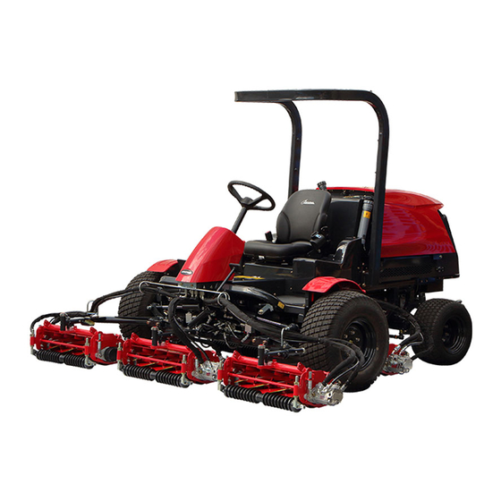
- Page 6 LM531 Introduction...
-
Page 7: Table Of Contents
LM531 Contents Safety .............. Page 1-1 Safe Operating Practices .......Page 1-2 Disposal ............Page 2-1 Recycle and Waste Disposal ......Page 2-2 Product Overview .......... Page 3-1 Specifications ..........Page 3-2 Names of Each Section ......... Page 3-4 Regulation Decals ..........Page 3-5 Safety Signs and Instruction Signs .... - Page 8 LM531 Contents...
-
Page 9: Safety
LM531 Safety Safe Operating Practices ...... Page 1-2 Training ..........Page 1-2 Preparation ..........Page 1-2 Operation ..........Page 1-3 Maintenance and Storage ..... Page 1-4 Page 1-1... -
Page 10: Safe Operating Practices
LM531 Safety Failure to adequately follow these safety Never allow children or people unfamiliar precautions may cause an accident resulting in with these instructions to use or service the injury or death. machine. Local regulations may restrict the age of the... - Page 11 LM531 Safety Exercise care in the handling of fuel. Remember there is no such thing as a safe slope. Travel on grass slopes requires Warning particular care. To guard against overturning: Warning-Fuel is highly flammable. Take the following precautions. Do not stop or start suddenly when going up or downhill.
- Page 12 LM531 Safety After striking a foreign object or if an Do not operate the machine when there is abnormal vibration occurs. the risk of lightning. Inspect the machine for damage and Maintenance and Storage make repairs before restarting and operating the equipment.
- Page 13 LM531 Safety When checking the hydraulic circuit for pinhole leaks or oil leakage from nozzles, do not use your hands. Use items such as paper or corrugated cardboard to find leakage points. Be extremely careful with high-pressure oil as it may pierce your skin, resulting in an injury.
- Page 14 LM531 Safety Page 1-6 Safe Operating Practices...
-
Page 15: Disposal
LM531 Disposal Recycle and Waste Disposal ....Page 2-2 About Recycle ........Page 2-2 About Waste Disposal ......Page 2-2 Page 2-1... -
Page 16: Recycle And Waste Disposal
LM531 Disposal Recycle and Waste Disposal About Recycle Recycling battery etc. is recommended for environmental conservation and economical use of resources. It may be required by local laws. About Waste Disposal Make sure that waste generated when servicing or repairing the machine is disposed of in accordance with local regulations. -
Page 17: Product Overview
LM531 Product Overview Specifications ........Page 3-2 Specifications .........Page 3-2 Sound Pressure Level ......Page 3-3 Sound Power Level ....... Page 3-3 Vibration Level ........Page 3-3 Carbon Dioxide (CO2) Emissions Measurement .........Page 3-3 Names of Each Section ......Page 3-4 Regulation Decals ........Page 3-5... -
Page 18: Specifications
LM531 Product Overview Specifications Specifications Model LM531 Total length 119.29 in 303 cm During 116.5 in 296 cm operation Dimensions Total width During 86.6 in 220 cm transport Total height Steering wheel 52.4 in 133 cm Machine with Slight lift... -
Page 19: Sound Pressure Level
LM531 Product Overview Sound Pressure Level Sound Pressure Level This machine was confirmed to have a continuous A-weighted sound pressure level of 88 dB by measuring identical machines in accordance with the procedure specified in ISO5395-1:2013. Sound Power Level Sound Power Level... -
Page 20: Names Of Each Section
LM531 Product Overview Names of Each Section Steering wheel Seat Throttle lever Mower unit up/down lever Reel rotation switch Light switch Stop valve Mower lock lever (Latch) Reel reverse switch Reel rotation/stop switching lever Traveling pedal Brake pedal Parking brake lock lever... -
Page 21: Regulation Decals
LM531 Product Overview Description of Regulation Decals Regulation Decals Serial Number Plate Positions of Regulation Decals The serial number plate indicates the model and serial number of the machine. 4ogipb-001 Serial Number Plate_001 Specification Decal G,H,I (For Europe) CE mark indicates that the machine sold in the EU nations complies with the EU requirements. - Page 22 LM531 Product Overview Noise Emission Decal ROPS Caution Decal (For Europe) ROPS caution decal describes the following The noise emission decal indicates the sound caution messages. power level determined by measuring Replace damaged ROPS. ・ identical machines in accordance with the Do not repair or revise.
- Page 23 LM531 Product Overview Recycle Decal Indicating Diesel Fuel Decal Recycle Decal illustrates Recycle Mark in (for USA) accordance with local regulation. It indicates the fuel to be used. (For Europe) Use low sulfur or ultra-low sulfur diesel fuel (sulfur-free diesel fuel).
- Page 24 LM531 Product Overview Spark Arrester Warning Decal (For the State of California, USA) Spark arrester warning decal describes the warning messages as required by California Public Resources Code. bfaymx-001 Spark Arrester Warning Decal_001 Page 3-8 Regulation Decals...
-
Page 25: Safety Signs And Instruction Signs
Positions of Safety Decals and Instruction Decals_002 Part numbers for decals that need to be replaced are listed in the parts catalog. Order them from a Baroness dealer or Kyoeisha. Positions of Safety Decals and Instruction Decals quwxcl-214... -
Page 26: Description Of Safety Decals And Instruction Decals
LM531 Product Overview Decal for operation 2 Caution Hydraulic oil icon Diesel fuel icon Rollover - Do not work on slopes of 15 Fire prohibited decal degrees or more. Decal on reading owner's operating When you descend a slope, lower the mower manual units and then drive at low speed. - Page 27 LM531 Product Overview Hydraulic Oil Icon Fire Prohibited Decal K4209000980 K4205001940 Hydraulic oil icon Decal, fire prohibited Read the Owner's Operating Manual. Warning Keep away from fire. i77xz6-001 Hydraulic Oil Icon_001 Diesel Fuel Icon r653fo-001 K4209001000 Fire Prohibited Decal_001 Diesel fuel icon Decal on Reading Owner's Operating Manual Use diesel fuel.
- Page 28 LM531 Product Overview Caution to Rotating Object Decal Caution for Spouting Coolant Decal K4205001530 K4205001970 Decal, caution to rotating object Decal, caution for spouting coolant Warning Caution Watch for rotating parts - Keep your hands Caution for spouting coolant - Do not open away from the belts while the engine is while hot.
- Page 29 LM531 Product Overview Caution for Mower Lock Decal K4205001900 Decal, caution for mower lock Lock the mower units when traveling or storing with the mower units #4 and 5 raised. K 4 2 0 5 0 0 1 9 0 0...
- Page 30 LM531 Product Overview Page 3-14 Safety Signs and Instruction Signs...
-
Page 31: Handling Instructions
LM531 Handling Instructions Inspections ..........Page 4-2 Stop Valve ........... Page 4-28 Mower Lock Lever (Latch) ....Page 4-28 Radiator Cover ........Page 4-2 Reel Rotation Switch ......Page 4-28 Radiator ..........Page 4-2 Reel Reverse Switch ......Page 4-29 Coolant ..........Page 4-3 Reel Rotation/Stop Switching Lever .. -
Page 32: Inspections
LM531 Handling Instructions Pull the radiator cover to the back to open Inspections Inspect the machine according to the maintenance schedule so that you will be able to take advantage of its optimum performance for a long period of time. -
Page 33: Coolant
LM531 Handling Instructions Loosen the knobs on the left and right of Coolant Supply the oil cooler, and then tilt the oil cooler. Caution Do not touch the radiator or coolant during engine operation or right after the engine has been turned off. -
Page 34: Oil Cooler
LM531 Handling Instructions If the oil cooler has been contaminated with Reserve tank dust, be sure to clean it. Reserve tank cap After operating the machine in a dusty environment, it is important to remove dust as If no coolant is in the reserve tank, follow soon as possible. - Page 35 LM531 Handling Instructions Open the tank cap and pour hydraulic oil Hydraulic Oil Supply from the fill port until the oil level reaches the middle of the oil gauge on the Important hydraulic tank. Do not mix different types of oil.
-
Page 36: Air Cleaner
LM531 Handling Instructions Attach the air cleaner element to the air Air Cleaner cleaner body. Inspection of Air Cleaner Replace the air cleaner cap, and then fix it securely with the clips. For details on handling the engine, please refer to the separate Engine Handling Manual. -
Page 37: Battery
LM531 Handling Instructions Battery Supply of Battery Fluid Inspection of Battery Danger Danger Be careful not to let your skin, eyes or clothes, Danger Danger etc., come into contact with the battery fluid or Keep fire away while inspecting or charging accidentally swallow the fluid. -
Page 38: Tire
LM531 Handling Instructions Tire Belt Inspection of Tires Inspection of Belt Check the pneumatic pressure of the tires. Warning Make sure that there are no cracks, The engine must be stopped when the belt is damage or abnormal wear. inspected. -
Page 39: Engine Oil
LM531 Handling Instructions Engine Oil Supply of Engine Oil Inspection of Engine Oil For details on handling the engine, please refer to the Owner’s Manual for the engine. For details on handling the engine, please Important refer to the Owner’s Manual for the engine. -
Page 40: Fuel
LM531 Handling Instructions Fuel Inspection of Fuel Quantity With the machine on a level surface, observe the fuel gauge in the operation panel to check the fuel level. F U E L 2e4emp-001 Fuel Supply_001 Fuel gauge Refuel up to the middle (marked in red) of the F U E L fuel gauge. -
Page 41: Water Separator
LM531 Handling Instructions Close the fuel filter cock. Water Separator Close the fuel cock of water separator. Inspection of Water Separator For details on handling the engine, please refer to the Engine's Owner's Manual. Important Water contamination in the fuel may decrease... - Page 42 LM531 Handling Instructions Open the fuel cock of water separator. Close the fuel cock of water separator. v1spa6-005 v1spa6-005 Draining of Water Separator_003 Cleaning of Water Separator_001 Fuel cock Fuel cock Air-bleeding plug Air-bleeding plug ON (Open) ON (Open) OFF (Close) OFF (Close) Loosen the air-bleeding plug by one turn.
-
Page 43: Fuel Filter
LM531 Handling Instructions Open the fuel cock of water separator. Oil Leakage Inspection of Oil Leakage Caution When performing maintenance on the hydraulic system, lower the mower units. After approximately 50 hours of operation, some tightened portions may be loosened and oil and grease may leak. -
Page 44: Tightening Torques
LM531 Handling Instructions Tightening Torques Important Refer to the Tightening Torque table. Note that the Baroness product warranty may not apply to defects caused by incorrect or overtorque tightening, etc. Standard Tightening Torques Bolts and Nuts Important A number of bolts are used in each part of this machine. - Page 45 LM531 Handling Instructions General bolt Strength classification 4.8 Nominal diameter tib3yb-001 kgf-cm lb-in 3 - 5 30.59 - 50.99 26.55 - 44.26 7 - 9 71.38 - 91.77 61.96 - 79.66 14 - 19 142.76 - 193.74 123.91 - 168.17 29 - 38 295.71 - 387.49...
-
Page 46: Principal Tightening Torques
LM531 Handling Instructions Principal Tightening Torques Tightening Torque by Model LM531 Tighten the following bolts and nuts to the torque specified in the table. For thread locking adhesive, apply a medium strength thread locker (ThreeBond 1322 anaerobic adhesive or equivalent). -
Page 47: Adjustment Before Work
LM531 Handling Instructions Adjustment of Seat Adjustment before Work Use the seat adjustment levers to adjust the Adjustment of Steering Wheel seat. Adjust the position to fit the operator. Warning Use the forward/backward adjustment lever Since it is dangerous, do not adjust the to adjust the seat back and forth. -
Page 48: Adjustment Of Mower Stopper Pin
LM531 Handling Instructions To release: Adjustment of Mower Stopper Pin Insert the cotter pin into the lower hole in the mower stopper pin. Note: Depending on the specifications, this function may not be available. The mower stopper pin can prevent or allow tilting of the mower units. -
Page 49: Procedure To Start/Stop Engine
LM531 Handling Instructions Procedure to Start/Stop Engine Fuel cock ON (Open) Start/Stop of Engine OFF (Close) Procedure to Start Engine Sit on the seat. Depress the brake pedal and move the Caution parking brake lock lever forward to lock the brake. - Page 50 LM531 Handling Instructions Make sure that the charge lamp and oil Important pressure lamp turn off. If they do not turn off, stop the engine and The thermo-start lamp turns off at the inspect the machine. specified time. However, the lamp turning off is not related to the glow plug generating heat.
-
Page 51: Operation Method
LM531 Handling Instructions Safety Mechanisms Operation Method This machine features a safety device for Cautions for when You Leave The starting/stopping the engine. Machine As for starting the engine, the safety device prevents the engine from starting unless it Caution meets each of the following four conditions. - Page 52 LM531 Handling Instructions 6n6oux-038 6n6oux-194 Positions of Operation Decals_002 Positions of Operation Decals_006 Mower unit up/down decal Key switch decal Reel rotation mark Engine rotation mark Traveling/working selector mark Light switch mark Stop valve operation decal Tilt steering decal Brake mark...
-
Page 53: Description Of Operation Decals
LM531 Handling Instructions Description of Operation Decals Reel Rotation Mark Mower Unit Up/Down Decal Reel rotation mark It illustrates Rotation/Stop of the reel cutter Decal, mower unit up/down (cutting cylinder). This indicates the Up/Down positions of the mower unit. 6ntnq3-001... - Page 54 LM531 Handling Instructions Traveling/Working Selector Mark Stop Valve Operation Decal Traveling/working selector mark K4203001290 It illustrates the positions where mower units Stop valve operation decal #4 and #5 stop when they are raised. It illustrates Stop/Open of the stop valve.
- Page 55 LM531 Handling Instructions Brake Mark BACKWARD Decal K4209001200 K4203001440 DECAL, BRAKE Decal, BACKWARD It illustrates the locking position for the This indicates backward travel. parking brake. BACKWARD kqca3e-002 7elqr2-002 BACKWARD Decal_001 Brake Mark_001 Lapping Switch Decal BRAKE Decal K4203001580 K4203001450...
-
Page 56: Light Switch
LM531 Handling Instructions Light Switch Reel Rotation Decal K4203001300 Caution Decal, reel rotation This indicates rotation of the reel cutter The lights provide auxiliary lighting. (cutting cylinder). Do not travel or operate the machine at night or under poor visibility. -
Page 57: Throttle Lever
LM531 Handling Instructions The mower unit up/down lever is located in the Throttle Lever operation panel and raises or lowers the mower units. The throttle lever is located in the operation Shift the lever to the "DOWN" position to lower panel and enables you to adjust the engine all the mower units, and shift it to the "UP"... -
Page 58: Stop Valve
LM531 Handling Instructions Stop Valve Reel Rotation Switch Caution Caution When you move the machine, or if you stop The reel rotation switch must be set just the engine with the mower units raised, be before you start cutting work. In cases other sure to set the stop valve to the "Stop"... -
Page 59: Reel Reverse Switch
LM531 Handling Instructions Reel Rotation/Stop Switching Lever Reel rotation switch Rotate (Slight lift function "ON") Caution Stop (Slight lift function "OFF") Before operating the reel rotation/stop Reel Reverse Switch switching lever, be sure to shift the reel rotation switch to the "Stop" position. -
Page 60: Traveling Pedal
LM531 Handling Instructions Traveling Pedal Parking Brake Lock Lever The traveling pedal is located in the right foot Caution area. When the forward side depressed, the machine Never park the machine on a slope. travels forward. When the backward side depressed, the machine travels backward. -
Page 61: Hood
LM531 Handling Instructions Hood Underseat Cover Caution Caution Do not open the hood in strong winds. Be careful not to pinch your fingers when you open or close the underseat cover. Caution Bring the seat to the most front position. -
Page 62: Instruments
LM531 Handling Instructions Instruments Instruments on the Operation Panel igozke-001 Water Temperature Gauge_001 Water temperature gauge Fuel Gauge The fuel gauge is located in the operation panel. This instrument indicates the quantity of fuel inside the fuel tank. kz7ka6-014 F U E L... -
Page 63: Pilot Lamps
LM531 Handling Instructions Pilot Lamps Thermo-start lamp Oil Pressure Lamp Charge Lamp The oil pressure lamp is the right pilot lamp The charge lamp is the left pilot lamp located located in the operation panel. in the operation panel. It turns on when the ignition key is set to the It turns on when the ignition key is set to the "ON"... -
Page 64: Move
LM531 Handling Instructions Depress the brake pedal to release the Hour Meter parking brake. The hour meter indicates the accumulated Slowly depress the traveling pedal. operation time of the engine. The machine starts traveling. The number in red figures on a white... -
Page 65: Towing The Machine
LM531 Handling Instructions Rear side Towing the Machine If the machine does not travel due to engine trouble, etc., you can move it in the following ways: Caution Before restarting the engine, be sure to tighten the unload valve. Important... -
Page 66: Cutting Work
LM531 Handling Instructions Release the mower lock levers (latches) for Cutting Work mower units #4 and #5. Cutting Operation Shift the mower unit up/down lever to the "DOWN" position to lower the mower units. Warning Set the reel rotation switch to the "Rotate"... -
Page 67: Transporting
LM531 Handling Instructions Grass catcher Grass catcher mounting bracket Mounting pin Mower units #1, 4 & 5 Note: The illustration shows the mower units #1 & 5. Right and left positions of the grass catcher mounting brackets differ according to the location of a mower unit. - Page 68 LM531 Handling Instructions Page 4-38 Storage...
-
Page 69: Maintenance
LM531 Maintenance Maintenance Precautions ..... Page 5-2 Maintenance Schedule ......Page 5-3 Adjusted Value ........Page 5-7 Jacking Up The Machine .......Page 5-8 About Jacking Up The Machine .....Page 5-8 Jack-Up Points ........Page 5-8 Greasing ..........Page 5-9 About Greasing ........Page 5-9 Greasing Points ........ -
Page 70: Maintenance Precautions
Use tools appropriate for each maintenance operation. Important For the safe and best performance of your machine, use Baroness genuine parts for replacement and accessories. Please note that our product warranty may be void if you use non-genuine parts for replacement or accessories. -
Page 71: Maintenance Schedule
LM531 Maintenance Maintenance Schedule LM551 Follow the maintenance schedule below. ○・・・Inspect, adjust, supply, clean ●・・・Replace (first time) △・・・Replace Maintenance Item Remarks Check engine oil level and ○ ... - Page 72 LM531 Maintenance Maintenance Item Remarks Clean radiator ○ screen Clean radiator core ○ ...
- Page 73 LM531 Maintenance Maintenance Item Remarks Clean air cleaner element (Replace in normal ○ △ the element after 6- conditions time cleaning) Check cracks in ...
- Page 74 LM531 Maintenance Maintenance Item Remarks Check every Check hydraulic 200 hours or hoses condition every year ○ ○ (Fixed part) whichever comes earlier...
-
Page 75: Adjusted Value
Replace brake pads △ *1: Consult your local Baroness Dealer or local KUBOTA Dealer for this service. ・ The items above (*2 marked) are registered as emission related critical parts by KUBOTA in the ・... -
Page 76: Jacking Up The Machine
LM531 Maintenance Jack-Up Points Jacking Up The Machine About Jacking Up The Machine Warning When replacing a tire or beginning any other maintenance or repairs, be sure to chock the wheels to prevent the machine from moving. Before jacking up the machine, park it on a... -
Page 77: Greasing
LM531 Maintenance Front left frame Other locations where the specified grease or lubricant is used are indicated in "Greasing Points". Add grease using the specified grease or lubricant. Greasing Points Grease nipples are installed in the following locations. Add grease every 50 hours of operation. - Page 78 LM531 Maintenance Pedal shaft fulcrum Mower unit #2 and 3 There are two greasing points. 8bq62b-176 8bq62b-173 Greasing Points_005 Mower unit fulcrum Greasing Points_002 Lift arm fulcrum There is one greasing point on each mower There is one greasing point on each lift arm unit.
- Page 79 LM531 Maintenance Rear left wheel 8bq62b-451 8bq62b-182 Greasing Points_011 Cylinder shafts #4 and 5 Greasing Points_008 Rear right wheel There is one greasing point each on the cylinder shafts. 8bq62b-183 8bq62b-452 Greasing Points_009 Cylinder shaft Greasing Points_012 Cylinder shaft #1 There are two greasing points on the cylinder shaft.
-
Page 80: Lubrication
LM531 Maintenance Mower cylinder spherical bearing Lubrication There is one point on each mower cylinder. Mower cylinder #2 and 3 About Lubrication It is necessary to lubricate moving parts so that they will not become stuck or damaged. The locations where lubricant is used are indicated in "Lubricating Points". -
Page 81: Maintenance Work
LM531 Maintenance Rear left wheel Rear Tire Follow the steps below to remove the rear tires: Loosen the bolts. 8bq62b-212 Lubricating Points_005 Maintenance Work Removing/Installing Tires upekw4-002 Rear Tire_001 Front Tires Heat-treated bolt Follow the steps below to remove the front... -
Page 82: Adjustment Of Belt Tension
LM531 Maintenance Adjustment of Belt Tension Adjustment of Parking Brake Warning Danger Danger Be sure to stop the engine before adjusting If the brake wire is cut, the machine will be the belts. unable to stop. This would be extremely dangerous. -
Page 83: Adjustment Of Brake
LM531 Maintenance Adjustment of Brake Danger Danger It would be extremely dangerous and may Danger Danger result in an unexpected accident if the left and right brakes are not equally effective. If the brake wire is cut, the machine will be unable to stop. -
Page 84: Adjusting The Neutral Position Of The Piston Pump
LM531 Maintenance Adjusting the Neutral Position of the Piston Pump Caution Make sure not to touch rotating tires. Caution When adjusting the neutral position, pay close attention to abrupt start of the machine. hsn2jo-012 Place the jacks beneath the jack-up points,... -
Page 85: Change Of Coolant
LM531 Maintenance Change of Coolant LLC concentration Freezing temperature (volume %) Caution Down to -10 °C (14 °F) 20 % Down to -15 °C (5 °F) 30 % Do not touch the radiator or coolant during Down to -20 °C (-4 °F) -
Page 86: Change Of Hydraulic Oil Filter
LM531 Maintenance Remove the reserve tank. Important When replacing the hydraulic oil filter, be sure to drain the oil into a container and discard it in accordance with local laws and regulations. Important If the hydraulic oil emulsifies or if it becomes even slightly less transparent, change the oil immediately. - Page 87 LM531 Maintenance Install the intake hose joint fitting. Change of Hydraulic Suction Filter Caution Be careful with hot oil, which could cause burns if it contacts your skin. Important When replacing the hydraulic oil filter, be sure to drain the oil into a container and discard it in accordance with local laws and regulations.
-
Page 88: Change Of Hydraulic Oil
LM531 Maintenance Remove the drain plug of the hydraulic Change of Hydraulic Oil tank, and then drain the old oil into a container. Caution Wind new sealing tape on the drain plug, When you change the hydraulic oil, be sure to and then attach it to the hydraulic tank. -
Page 89: Change Of Air Cleaner
LM531 Maintenance Open the tank cap and pour hydraulic oil Change of Engine Oil from the fill port until the oil level reaches the middle of the oil gauge on the Warning hydraulic tank. When you change the engine oil, be sure to drain it into a bowl and discard it in accordance with local laws and regulations. -
Page 90: Change Of Engine Oil Filter
LM531 Maintenance Remove the oil filler cap, and then supply With the filter wrench, remove the old filter new engine oil until the oil reaches a level in cartridge. between the upper and lower limit lines on the oil level gauge. -
Page 91: Change Of Fuel Filter Element
LM531 Maintenance Clean the inside of the cup with light oil. Change of Fuel Filter Element Important If dust or dirt accumulates in the fuel filter, the When installed, be careful that it is not fuel flow will become insufficient. -
Page 92: Change Of Fuse
LM531 Maintenance Change of Fuse Glow lamp timer Glow lamp Important Fuel pump Charge lamp, oil pressure (engine oil pressure) When performing maintenance on the lamp, water temperature gauge, buzzer, hour electrical system, be sure to remove the meter, fuel gauge negative battery wire. - Page 96 1-26, Miyuki-cho, Toyokawa-city, Tel : +81 - 533 - 84 - 1390 Head Office Fax : +81 - 533 - 84 - 1220 Aichi-pref, 442-8530 JAPAN LM531---UM--GBZ/21H-00-S.K E00a[LM531_EU00a]...
Need help?
Do you have a question about the LM531 and is the answer not in the manual?
Questions and answers