Table of Contents
Advertisement
Quick Links
Advertisement
Table of Contents

Related Manuals for SUTO S409


Summary of Contents for SUTO S409
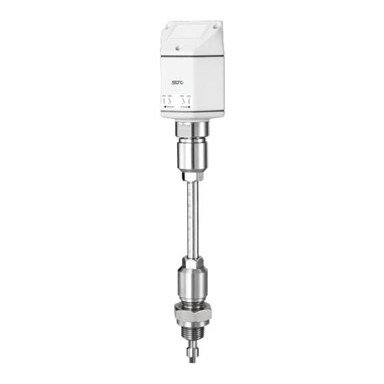
- Page 1 English Instruction and operation manual S409 Thermal Mass Flow Direction Switch...
- Page 2 The device is destined exclusively for the described application. SUTO offers no guarantee for the suitability for any other purpose. SUTO is also not liable for consequential damage resulting from the delivery, capability or use of this device.
-
Page 3: Table Of Contents
8 Installation ................11 8.1 Installation Requirements.............11 8.2 Installation Procedure ............11 8.3 Electrical connection ............13 8.3.1 Connection of S330/S331 to S450 ........15 8.3.2 Connection of S330/S331 to S401........15 9 Signal outputs................18 10 Optional accessories..............18 11 Maintenance................18 12 Disposal or waste..............18 S409... -
Page 4: Safety Instructions
• Consider all regulations for electrical installations. • The system must be disconnected from any power supply during maintenance work. • Any electrical work on the system is only allowed by authorized qualified personal. S409... - Page 5 • Always observe the direction of the flow when installing the sensor. The direction is indicated on the housing. • Do not exceed the maximum operation temperature at the sensors tip. • Avoid condensation on the sensor element as this will affect the accuracy enormously. S409...
-
Page 6: Registered Trademarks
• Avoid direct UV and solar radiation during storage. • For the storage the humidity must be <90%, no condensation. 2 Registered trademarks SUTO ® Registered trademark of SUTO iTEC MODBUS Registered trademark of the Modbus Organization, ® Hopkinton, USA HART ®... -
Page 7: Application
The S409 is not developed to be used in explosive areas. For the use in explosive areas please contact the manufacturer. -
Page 8: Technical Data
See dimensional drawing on the next page Tube diameter ½ to 12 (bigger diameters on request) Screwing thread G1/2” (ISO 228-1) Weight 509 g 5.2 Electrical Data Power supply 24 VDC, 60 mA 5.3 Output signals Alarm output 2 x relay, 60 V, 1 A S409... -
Page 9: Dimensional Drawing
6 Dimensional drawing 6 Dimensional drawing Unit: mm S409... -
Page 10: Determination Of The Installation Point
7 Determination of the installation point 7 Determination of the installation point In order to maintain the accuracy stated in the technical data, the S409 must be insert in the pipe without touching the inner wall of the pipe. Please consider that enough space exists at your site for a adequate installation as described in this manual. -
Page 11: Installation
• Ensure that there is a minimum clearance between S409 and the flow meter of at least 30 X D and the S409 is at least 20 X D away from any bend, or obstruction in the pipe. - Page 12 7. Tighten the clamp sleeve at the connection thread so that the S409 cannot be moved by the pressure in the pipe. However it should be possible to move the S409 shaft manually.
-
Page 13: Electrical Connection
4. Close the ball valve. 5. Release the connection thread and unscrew the S409. 8.3 Electrical connection The S409 is equipped with two M12 connectors “A” and “B”. The cables are connected to the S409 through the M12 connector. Connector A... - Page 14 Flow direction input 1 DIR2 Flow direction input 2 Not applicable ATTENTION! Do not screw the M12 connector using force. Otherwise, it may damage the connecting pins. Relay output at the switch Figure 1: Forward Direction Figure 2: Reverse Direction S409...
-
Page 15: Connection Of S330/S331 To S450
8.3.1 Connection of S330/S331 to S450 Note: Illustration of how to connect S409 to a bi-directional version of S450 and the SUTO display S330/S331. Of course the S409 can also be operated without the S330/S331 display unit. 8.3.2 Connection of S330/S331 to S401 Please note the following: •... - Page 16 Forward Direction Connector B Reverse Direction Connector A Modbus Note: Illustration of how to connect S409 to a bi-directional version of S401 and the SUTO display S330/S331. Of course the S409 can also be operated without the S330/S331 display unit. S409...
- Page 17 8 Installation Note: Illustration of how to connect S409 to a bi-directional version of S401 and the SUTO display S330/S331. Of course the S409 can also be operated without the S330/S331 display unit. S409...
-
Page 18: Signal Outputs
9 Signal outputs 9 Signal outputs The S409 has two relay outputs (60 V, 1 A). 10 Optional accessories The following accessories are available: • Sensor cable, 5 m, with the M12 connector on one end and open wires on the other. - Page 19 S409...
- Page 20 SUTO iTEC GmbH SUTO iTEC (ASIA) Co., Ltd. Grißheimer Weg 21 Room 10, 6/F, Block B, Cambridge Plaza D-79423 Heitersheim 188 San Wan Road, Sheung Shui, N.T. Germany Hong Kong Tel: +49 (0) 7634 50488 00 Tel: +852 2328 9782 Email: sales@suto-itec.com...
Need help?
Do you have a question about the S409 and is the answer not in the manual?
Questions and answers