
Related Manuals for SUTO S453


Summary of Contents for SUTO S453
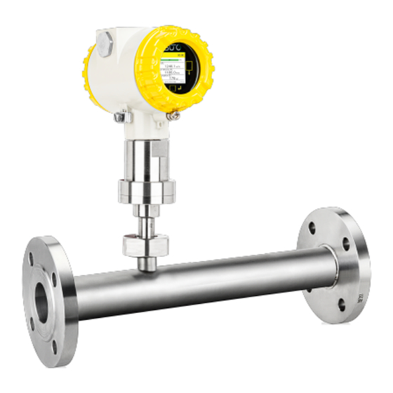
- Page 1 English Instruction and Operation Manual S453 Thermal Mass Flow Meter for Heavy Duty and Ex Applications (Inline)
- Page 2 The device is designed exclusively for the described application. SUTO offers no guarantee for the suitability for any other purpose. SUTO is also not liable for consequential damage resulting from the delivery, capability or use of this device.
-
Page 3: Table Of Contents
10.2.2 Specific Settings for Gas Flowmeters......30 10.3 Modbus/TCP Interface ............32 10.3.1 Modbus/TCP over Ethernet/APL ........32 10.3.2 Modbus/TCP over Single Pair Ethernet......32 10.4 Connection between S453 Outputs and Customer Equipment. .33 11 Operation Using the Display............36 11.1 Information on the Display..........36 11.1.1 Home Page..............36 11.1.2 Icons Shown in the Status Bar........37... - Page 4 12 Configuration Using S4C-FS App..........40 12.1 Configurable Parameters.............40 12.2 Alarm Settings..............41 12.3 Use the Service App S4C-FS..........42 13 Optional Accessories ..............43 13.1 Sensor Display..............43 14 Calibration................43 15 Maintenance................43 16 Disposal or Waste..............43 S453...
-
Page 5: Safety Instructions
• Consider all regulations for electrical installations. • The system must be disconnected from any power supply during maintenance work. • Any electrical work on the system is only allowed by authorized qualified personal. S453... - Page 6 • Always observe the direction of the flow when installing the sensor. The direction is indicated on the housing. • Do not exceed the maximum operation temperature at the sensors tip. • Avoid condensation on the sensor tip as this will affect the accuracy enormously. S453...
-
Page 7: Registered Trademarks
• Avoid direct UV and solar radiation during storage. • For the storage the humidity must be <90% with no condensation. 2 Registered Trademarks SUTO ® Registered trademark of SUTO iTEC MODBUS ® Registered trademark of the Modbus Organization, Hopkinton, USA Android™,... -
Page 8: Rf Exposure Information And Statement
• Connect the equipment into an outlet on a circuit different from that to which the receiver is connected. • Consult the dealer or an experienced radio/TV technician for help • This device and its antenna(s) must not be co-located or operating in conjunction with any other antenna or transmitter. S453... -
Page 9: Application
4 Application 4 Application The S453 Thermal Mass Flow Meter is designed for harsh and hazardous environments is mainly used to measure compressed air and process gases. The S453 can measure the following parameters: • Volumetric flow or mass flow •... -
Page 10: Technical Data
Response time (t 0.5 sec Consumption Selectable units Sm³, Sl, Scf, kg, Nm³, Nl, Ncf Pressure Accuracy 0.5% FS Selectable unit bar, psi, kPa, MPa Measuring range 0 ... 1.6 MPa(g) (option A1558) 0 ... 4.0 MPa(g) (option A1559) S453... -
Page 11: Output Signal/ Interface And Supply
30 VDC, 200 mA Scaling 1 pulse per consumption unit (selectable) Alarm Channel and threshold freely setable Fieldbus Protocol Modbus/RTU Modbus/TCP over Ethernet/APL or Modbus/TCP over single pair Ethernet Power supply Voltage, current, 16 ... 30 VDC, 200 mA, 5 W consumption S453... -
Page 12: General Data
0 ... 1.6 MPa(g) (option A1558) 0 ... 4.0 MPa(g) (option A1559) Ambient temperature -40 ... +65°C Storage temperature -40 ... +70°C Transport temperature -40 ... +70°C Fluid temperature -30 ... +90°C (Ex Version) -30 … +140°C Tube diameter DN25 ... DN80 S453... -
Page 13: Flow Ranges
• To calculate flow ranges based on pipe and reference conditions in your site, download and install the "Flow range calculator" tool for free from http://www.suto-itec.com. • To fast access the tool download page, enter "flowrange" (without spaces) in the search field and click the search result. -
Page 14: Dimensional Drawing
Thread size length length height to casing top inch (DN) (mm) (mm) (mm) (mm) 1” (DN25) R 1” 1¼”(DN32) R 1¼” 1½”(DN40) R 1½” 2” (DN50) R 2” 2½”(DN65) R 2½ ” 3” (DN80) 326.5 R 3” S453... -
Page 15: Flange Type
ØL ØD ØK casing top inch (DN) (mm) (mm) (mm) (mm) (mm) (mm) (mm) 1” (DN25) 339.5 4xØ14 1¼”(DN32) 4xØ18 1½”(DN40) 4xØ18 2” (DN50) 364.5 4xØ18 2½”(DN65) 374.5 8xØ18 3” (DN80) 8xØ18 S453... - Page 16 (DN) (mm) (mm) (mm) (mm) (mm) (mm) (mm) 1” (DN25) 339.5 123.9 88.9 4xØ19 1¼”(DN32) 133.3 98.5 4xØ19 1½”(DN40) 155.4 114.3 4xØ22.3 2” (DN50) 364.5 165.1 4xØ19 2½”(DN65) 374.5 190.5 149.3 8xØ22.3 3” (DN80) 209.5 168.1 8xØ22.3 S453...
-
Page 17: Determine The Installation Point
• Pay attention to the design of the inlet and outlet section. Obstructions can cause counter-flow turbulence as well as turbulence in the direction of the flow. • It is strongly recommended not to install S453 permanently in wet environment which exists usually right after a compressor outlet. S453... -
Page 18: Additional Inlet And Outlet Sections
The S453 with tube diameters of DN25 already has the required inlet and outlet sections. No additional straight sections are needed. For the S453 with diameters from DN32 to DN80, the S453 has a shortened inlet section and requires additional straight sections at the inlet and outlet. -
Page 19: Installation
The S453 is shipped with the mounted measurement section. When installing the device, please make sure the following: • The flow direction indicated on the S453 housing is consistent with the flow direction of the compressed air or gas. • The gas flows from the inlet (long pipe section) to the outlet (short pipe section) as illustrated in the picture below. -
Page 20: Remove The S453
9 Installation Note: The S453 can be installed in any orientation (horizontal, vertical, side and upside-down). Please consider the needed straight inlet and outlet sections described in section 8.1 Additional Inlet and Outlet Sections . 9.2 Remove the S453 ATTENTION! Only remove the flow meter if the system is in a pressure-less condition. -
Page 21: Electrical Connection
• Single wire cross section area must be between 0.25 ... 0.75 mm • The thread size for the cable glands is M20 / 1.5. 9.4.1 Connection diagram Remove the back cover from the S453, and the pin layout is shown as below. S453... -
Page 22: Pin Assignment
9 Installation 9.4.2 Pin Assignment The S453 provides 2 connection options. The pin assignment of these options are given in the following table. Output options Remarks Modbus/RTU Modbus/TCP Earth Earth GND_SDI GND_SDI 24 VDC power supply Digital interface SUTO sensor... -
Page 23: Signal Outputs
Pulse output The maximum number of pulse per second is limited to 49. In case that the flow rate is too high, the S453 cannot output the pulses with default settings (one pulse per consumption unit). In this case, you can set the pulse to 1 pulse per 10 consumption units or 1 pulse per 100 consumption units, using the S4C-FS service app. -
Page 24: Modbus Interface
10.2 Modbus Interface The Modbus communication requires to activate terminal resistors at the last device on the bus system. If the S453 is the last device on the bus system, the DIP switches on the connector board should be set to “ON”... - Page 25 Byte3-Byte2, is received from the slave (sensor), the master must change the byte order to Byte0-Byte1-Byte2-Byte3 for the correct display of the value. Remarks: Modbus communication settings as well as other settings can be changed by mobile app S4C-FS. S453...
- Page 26 INT16U 2-Byte Valid days from calibration date 2008 INT16U 2-Byte Number of measuring channels 2009 string 16-Byte Device name: “S451” or “S453” Settings 2100 Settings (max 50 holding register) Channel value information 2200 INT16U 2-Byte Unit+Resolution+type of channel 1 2201...
-
Page 27: Channel Value Information
/min mass Nl/min kg/h Mass Flow Nl/s kg/min Ncfm • Second byte: Bit7 Bit6 Bit5 Bit4 Bit3 Bit2 Bit1 Bit0 Data type: Resolution: 0 float, 1 4-byte unsigned integer 1 0.0 2 double 2 0.00 3 0.000 4 0.0000 S453... - Page 28 FLOAT Channel 2 Actual Velocity 2305 INT32U Channel 3 Consumption 2307 FLOAT Channel 4 Flow (R) 2309 FLOAT Channel 5 Actual Velocity (R) 2311 INT32U Channel 6 Consumption (R) 2313 FLOAT Channel 7 Pressure 2315 FLOAT Channel 8 Temperature S453...
- Page 29 Nm³/h, Ncfm, Nl/min 2203 Flow(R) Float Sm³/min, Sl/s, kg/min, 0.01 Nm³/min, Nl/s Kg/s 0.001 ft/min 2204 Velocity(R) Float Sm³, Sl, kg, Scf, Nm³, Nl, 2205 Consumption(R) INT32U 2206 Pressure Float bar, MPa 0.01 2207 Temperature °C, °F Float S453...
-
Page 30: Specific Settings For Gas Flowmeters
4-20 mA scaling of channel 1 Higher value 2125 Float 4-20 mA scaling of channel 2 lower value 2127 Float 4-20 mA scaling of channel 2 Higher value Coding of Calibration/Operation gas type Gas type Code Gas type Code Propane Butane Nat. gas S453... - Page 31 If there is any invalid setting performed the flow meter will respond the function code with MSB set to 1. In the data field there is error code: 01 illegal function code, 02 illegal data address, 03 illegal data value. S453...
-
Page 32: Modbus/Tcp Interface
The 10Base-T1L operates in the 2.4 Vpp mode and the cable length can be up to 1000 m. The power provision of the S453 supports 24V DC Power Class 12 (IEEE 802.3 cg) with integrated PoDL (Power Over Data Line) controller. -
Page 33: Connection Between S453 Outputs And Customer Equipment
10.4 Connection between S453 Outputs and Customer Equipment This section provides figures to show how outputs supported by the S453 connect with the customer equipment. In the following figures, the SUTO Instrument indicates the S453. Two analog outputs (Isolated) Pulse / Alarm output... - Page 34 10 Signal Outputs Modbus/RTU Ethernet/APL over Ethernet/APL Modbus/TCP over single pair Ethernet S453...
- Page 35 10 Signal Outputs Direction input SDI Sensor S453...
-
Page 36: Operation Using The Display
After powered up, the display starts an initialization procedure. After it is completed, it enters the standard mode, showing online values as below. Status bar Moving bar to indicate flow value Measured values Three optical keys on the S453 are available for operation. S453... -
Page 37: Icons Shown In The Status Bar
To see the details of the raised alarm, do the following: 1. Press the Enter button on the S453, then Menu page shows on the display. 2. On the Menu page, click Information > Alarm information. -
Page 38: Operation
01 00 00 00 Consumption checksum error 11.2 Operation By pressing the Enter key on the S453, the Menu page comes up. In order to perform any settings or calibration, the user has to enter a 4-digit password number under the Unlock menu. -
Page 39: Menu Map
11 Operation Using the Display 11.3 Menu Map S453... -
Page 40: Configuration Using S4C-Fs App
12 Configuration Using S4C-FS App 12 Configuration Using S4C-FS App 12.1 Configurable Parameters The S453 enables you to configure parameter settings according to the on-site requirements. The following table gives an overview about the available settings. Parameters Available settings Default... -
Page 41: Alarm Settings
Gateway Modbus/TCP Port over single pair Ethernet Timeout ≥200 ms To configure S453 settings, use the mobile app S4C-FS for the full settings or the local display for the most common settings. 12.2 Alarm Settings Parameter Description Settings Alarm Indicate if the alarm is enabled or... -
Page 42: Use The Service App S4C-Fs
SUTO flow meters wirelessly. Download S4C-FS from Google Play Store, the Apple Shop or SUTO website, and install it as you do for any apps on your mobile phone. For more information about introduces of the sensor settings,... -
Page 43: Optional Accessories
13 Optional Accessories 13 Optional Accessories 13.1 Sensor Display The S453 display shows the values of velocity, flow rate, consumption and error messages. 14 Calibration The flow meter is calibrated ex work. The exact calibration date is printed on the certificate which is supplied together with the flow meter. - Page 44 SUTO iTEC GmbH SUTO iTEC (ASIA) Co., Ltd. Grißheimer Weg 21 Room 10, 6/F, Block B, Cambridge Plaza D-79423 Heitersheim 188 San Wan Road, Sheung Shui, N.T. Germany Hong Kong Tel: +49 (0) 7634 50488 00 Tel: +852 2328 9782 Email: sales@suto-itec.com...
Need help?
Do you have a question about the S453 and is the answer not in the manual?
Questions and answers