Table of Contents
Advertisement
Quick Links
Advertisement
Table of Contents

Related Manuals for Pickering LXI 60-770


Summary of Contents for Pickering LXI 60-770
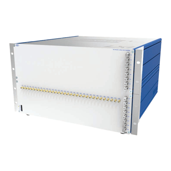
- Page 1 60-770 User Manual LXI 2.4 GHz RF Matrix pickeringtest.com Issue 3.5 January 2023...
- Page 2 © COPYRIGHT (2023) PICKERING INTERFACES. ALL RIGHTS RESERVED. No part of this publication may be reproduced, transmitted, transcribed, translated or stored in any form, or by any means without the written permission of Pickering Interfaces. Technical details contained within this publication are subject to change without notice.
- Page 3 Pickering Interfaces strives to fulfil all relevant environmental laws and regulations and reduce wastes and releases to the environment. Pickering Interfaces aims to design and operate products in a way that protects the environment and the health and safety of its employees, customers and the public. Pickering Interfaces endeavours to develop and manufacture products that can be produced, distributed, used and recycled, or disposed of, in a safe and environmentally friendly manner.
-
Page 4: Product Safety
PRODUCT SAFETY SAFETY SYMBOLS The following safety symbols may be used on the product and throughout the product documentation. MEANING / DESCRIPTION SYMBOL PROTECTIVE EARTH (GROUND) To identify any terminal which is intended for connection to an external conductor for protection against electric shock in case of a fault, or the terminal of a protective earth (ground) electrode. -
Page 5: Table Of Contents
CONTENTS Copyright Statement ..............II Technical Support and Warranty ..........III Product Safety ................IV Contents (this page) ..............V Warnings and Cautions .............. VII Section 1 Technical Specification ...............1.1 Section 2 Technical Desctiption ..............2.1 Section 3 Installation ..................3.1 Pre Operation Checks .............3.1 Hardware Installation ............3.1... - Page 6 THIS PAGE INTENTIONALLY BLANK LXI 2.4GHz MATRIX 60-770 Page (VI)
-
Page 7: Warnings And Cautions
I/O signals that may be present. Blanking panels are available to order from Pickering. If the product is not used in this manner for example by using an extender card then additional care must be taken to avoid contact with exposed signals. - Page 8 CAUTION - PRODUCT DOCUMENTATION SYMBOL Suitably qualified & trained users should ensure that the accompanying documentation is fully read and understood before attempting to install or operate the product. SAFETY INSTRUCTIONS SAFETY INSTRUCTIONS All cleaning and servicing requires the equipment to be isolated and disconnected from the power source and user I/O signals (refer to the Maintenance Section).
-
Page 9: Technical Specification
Y axis sizes of 16 and X axis sizes of 8, 16, 24 through Pickering Interfaces switch driver. and 32. The matrix is factory re-configurable up to the Pickering Interfaces can use the design methods applied to maximum size of 32x16. 60-770 to construct RF matrices with other architectures, The matrix exhibits excellent RF characteristics. - Page 10 SECTION 1 - TECHNICAL SPECIFICATION pickering Overview LXI 2.4 GHz Matrix, 60-770 Connections Y1 to Y16 50Ω SIGNAL TERMINATION SWITCHING LOOP-THRU SWITCHING 16-off Connections SMA to SMA X1 to X64 Loop-Thru Leads 50Ω SIGNAL TERMINATION SWITCHING LOOP-THRU SWITCHING Example of how two 60-770-001 32x16 matrices can be interlinked to create a 64x16 matrix. Sixteen SMA to SMA leads are used to link the Y Loop-Thru connections from the first matrix to the Y connections of the second matrix.
- Page 11 SECTION 1 - TECHNICAL SPECIFICATION pickering Specifications LXI 2.4 GHz Matrix, 60-770 60-770 Typical Insertion Loss - Y to Y Loop-Thru 60-770 Typical Insertion Loss - X to Y Thru Path 60-770 Typical VSWR - X to Y Thru Path...
- Page 12 SECTION 1 - TECHNICAL SPECIFICATION pickering Specifications LXI 2.4 GHz Matrix, 60-770 60-770 Typical Crosstalk 60-770 Typical Isolation - X to Y 60-770 Typical Isolation - X to X 60-770 Typical Isolation - Y to Y 60-770 Typical Isolation - Y to Y Loop-Thru pickeringtest.com...
- Page 13 SECTION 1 - TECHNICAL SPECIFICATION pickering Specifications LXI 2.4 GHz Matrix, 60-770 General Matrix Information LAN Interface Compliant to LXI Standard 1.4, the 60-770 has a Matrix Size: 32x16, 24x16 or 16x16 1000Base-T Ethernet Interface via a standard RJ-45 Connectors:...
- Page 14 Connection Solutions catalog. Product Customization Pickering LXI units are designed and manufactured on our own flexible manufacturing lines, giving complete product control and enabling simple customization to meet very specific requirements.
- Page 15 To learn more, please go to: pickeringrelay.com Programming Pickering provide kernel, IVI and VISA (NI & Keysight) drivers which are compatible with all Microsoft supported versions of Windows and popular older versions. For a list of all supporting operating systems, please see: pickeringtest.com/os The VISA driver support is provided for LabVIEW Real Time Operating Systems (Pharlap and Linux-RT).
- Page 16 Three Year Warranty & Guaranteed Long-Term Support All standard products manufactured by Pickering Interfaces are warranted against defective materials and workmanship for a period of three years from the date of delivery to the original purchaser. Extended warranty and service agreements are available for all our modules and systems with various levels to suit your requirements.
- Page 17 SECTION 2 - TECHNICAL DESCRIPTION pickering SECTION 2 - TECHNICAL DESCRIPTION The 60-770 is an RF matrix arranged in 32x16, 24x16 or 16x16 format under the control of an LXI interface designed for the routing of signals with frequencies up to 2.4GHz. An overall block diagram for the unit is shown in Figure 2-1.
- Page 18 Programming information for the processor is sent to the unit via the LAN interface from a remote computer using the unit’s unique Ethernet address. Programming documentation for the unit as well as data for Pickering’s other LXI compatible switching products is stored in the embedded processor and can be downloaded over the LAN interface.
-
Page 19: Installation
The product is designed for indoor use only. PREOPERATION CHECKS (UNPACKING) 1. Check the module for transport damage and report any damage immediately to Pickering Interfaces. Do not attempt to install the product if any damage is evident. 2. Ensure that the designated area for the product is of a flat and solid construction to support its weight. -
Page 20: Setting The Ip Address
SECTION 3 - INSTALLATION pickering Cooling Air Intake (left hand side) Figure 3-1. Rear view of the 60-770 RF Matrix showing the mains supply connection with power switch, LAN socket and the Reset button. Cooling air is drawn through slots in the left and right side extrusions... -
Page 21: Instaliing The Software
SECTION 3 - INSTALLATION pickering Figure 3-3. Example configuration window used to manually set the IP address of a Pickering LXI device INSTALLING THE SOFTWARE From the device web page, select ‘Driver Download’ from the menu at the left of the page. This will retrieve the driver from the instrument and install it on your PC. - Page 22 SECTION 3 - INSTALLATION pickering THIS PAGE INTENTIONALLY BLANK LXI 2.4GHz MATRIX 60-770 Page 3.4...
-
Page 23: Programming Guide
SECTION 4 - PROGRAMMING GUIDE PROGRAMMING OPTIONS FOR PICKERING INTERFACES LXI UNITS For information on the installation and use of drivers and the programming of Pickering’s products in various software environments, please refer to the Software User Manual. This is available as a download from: https://www.pickeringtest.com/support/software-drivers-and-downloads... -
Page 24: Programming The 60-770
SECTION 4 - PROGRAMMING GUIDE pickering PROGRAMMING THE 60-770 The 60-770-001 is a single matrix with 32 connections on its X axis and 16 on its Y axis, and is the largest of the 60-770 range RF matrices. For the purposes of programming, the 32x16 matrix is treated as a single sub-unit. - Page 25 The Direct I/O driver is in reality composed of a suite of separate libraries which interact to provide full control of a Pickering LXI unit. In the case of a switch card the communications library picmlx, and the switching library piplx, are needed.
- Page 26 The following code snippet demonstrates the minimum steps required to operate a switch on a Pickering LXI unit. Firstly a device session is opened on the LXI unit located at 192.168.1.100, the bus and device location is dealt with automatically by the driver.
- Page 27 SECTION 4 - PROGRAMMING GUIDE pickering SSH Interface Refer to later section for details of how to open this interface and general information on the command set available. After opening an SSH session the 60-770 is controlled as follows: To select a matrix crosspoint type XC followed by the required row and column separated by a comma, eg: XC 2,4 To clear a matrix crosspoint type XO followed by the required row and column separated by a comma, eg: XO 2,4 Or, to clear all matrix crosspoints, issue a clear sub-unit command, CS.
-
Page 28: Command Line Control
LXI instrument from the Windows utility PILMon and provides identical functionality. Enabling the Command Line Control Utility Pickering LXI devices do not provide an SSH server in the normal configuration state, the service must be explicitly enabled. - Page 29 SECTION 4 - PROGRAMMING GUIDE pickering Step 2 - Enable the SSH server Select the Diagnostics page from the main menu LXI 2.4GHz MATRIX 60-770 Page 4.7...
- Page 30 SECTION 4 - PROGRAMMING GUIDE pickering Click on Start SSH server The SSH server is now operative and instrument control access is available from an external SSH client application. NOTES: The password and state of the SSH server are stored in non-volatile memory within the LXI device and so will remain in effect even after a power cycle.
- Page 31 SECTION 4 - PROGRAMMING GUIDE pickering Instrument Control from an SSH Client In the following examples the SSH client PuTTY is used, the user will have to adapt the instructions for any other client. First start up the SSH client and enter the IP address of the LXI device. The user will be prompted for a login name and password.
- Page 32 Before attempting to control a card it is important to understand the switch architecture of that card and to know how to address the required switch. Each Pickering switch card is represented as a set of one or more sub-units, each sub-unit containing one or more switches.
- Page 33 SECTION 4 - PROGRAMMING GUIDE pickering Commonly used mnemonic commands Will list all the open cards, providing the Card Number of each which is essential for further control of a card, also provided are the details of the card model number and architecture.
- Page 34 = UNMASK|MASK an individual output MB <bit_pattern> = set OUTPUT sub-unit mask (to hex bit-pattern) = view sub-unit output mask (as hex bit-pattern) = take control of all Pickering switch cards = release control of all Pickering switch cards VO <bus> <slot> = open card at specified location VC <card>...
-
Page 35: Using The Soft Front Panel
SECTION 4 - PROGRAMMING GUIDE pickering USING THE SOFT FRONT PANEL LXI 2.4GHz MATRIX 60-770 Page 4.13... - Page 36 SECTION 4 - PROGRAMMING GUIDE pickering THIS PAGE INTENTIONALLY BLANK LXI 2.4GHz MATRIX 60-770 Page 4.14...
-
Page 37: Connections
SECTION 5 - CONNECTOR INFORMATION pickering SECTION 5 - CONNECTIONS Figure 5-1. Front Panel Connector Layout for the 60-770 LXI RF Matrix (32x16 version) LXI 2.4GHz MATRIX 60-770 Page 5.1... - Page 38 SECTION 5 - CONNECTOR INFORMATION pickering Ethernet Port Reset Button Service Port (for Pickering diagnostics only) IP Address Display Power Switch Fuses Mains Inlet Figure 5-2. Rear Panel Connector Layout for the 60-770 LXI RF Matrix LXI 2.4GHz MATRIX 60-770...
-
Page 39: Trouble Shooting
Refer to the Warnings and Cautions at the front of this manual INSTALLATION PROBLEMS The Plug & Play functionality of Pickering switching products generally ensures trouble-free installation. If you do experience any installation problems you should first ensure that all cables are properly connected. -
Page 40: Lan Reset
Q All of my device’s lights are on, why don’t I see a green Ready light, even after a few minutes? Your device has a fault, contact your local sales office. Please contact your local Pickering Interfaces sales office for any further support or email: support@pickeringtest.com You can also visit our website for product updates, help and downloadable materials at: http://www.pickeringtest.com... -
Page 41: Maintenance Information
SECTION 7 - MAINTENANCE INFORMATION SECTION 7 - MAINTENANCE INFORMATION pickering pickering SECTION 7 - MAINTENANCE INFORMATION Refer to the Warnings and Cautions at the front of this manual PERIODIC MAINTENANCE This product does not require any periodic maintenance. GENERAL CLEANING •... - Page 42 SECTION 7 - MAINTENANCE INFORMATION pickering THIS PAGE INTENTIONALLY BLANK LXI 2.4GHz MATRIX 60-770 Page 7.2...
-
Page 43: Fitting Rack Mounting Flanges
APPENDIX A - FITTING RACK MOUNTING FLANGES Pickering’s LXI devices are supplied with mounting flanges to enable fitting into a standard 19 inch rack. The following procedure describes the attachment of the flanges to the unit’s side extrusions, a No.1 cross head screwdriver will be required. - Page 44 APPENDIX A - FITTING RACK MOUNTING FLANGES pickering THIS PAGE INTENTIONALLY BLANK LXI 2.4GHz MATRIX 60-770 Page A.2...
Need help?
Do you have a question about the LXI 60-770 and is the answer not in the manual?
Questions and answers