Table of Contents
Advertisement
Quick Links
Advertisement
Table of Contents

Related Manuals for Golander pump CT3000F


Summary of Contents for Golander pump CT3000F
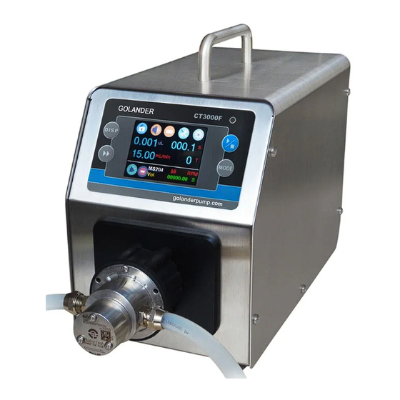
- Page 1 CT3000F Intelligent Dispensing Gear Pump Operating Manual...
-
Page 2: Table Of Contents
Contents Safety Precautions ................1 1 Introduction ..................2 2 Functions and Features ..............2 3 Specifications ..................3 4 Components and Connectors ............4 5 Display Panel and Operating Keypads ..........5 5.1 Keypad ................... 5 5.2 LCD Touch Screen Display ............6 5.3 System Settings .............. -
Page 3: Safety Precautions
Golander CT3000F Dispensing Gear Pump Safety Precautions Danger • Please use the correct AC power voltage source shown on the sticker attached to the equipment to avoid any damage. Please do not open the case. It may cause malfunction or electric shock. For maintenance, please contact the manufacturer or distributor directly. -
Page 4: Introduction
The gear pump can only transfer liquid in one direction. 1 Introduction CT3000F is a high-performance, low-noise micro gear pump, providing a speed range from 50 to 3000 rpm, with a 1 rpm resolution. Its brushless servo motor and stainless-steel magnetic drive pump head enable the continuous and smooth transfer of fluids. -
Page 5: Specifications
Golander CT3000F Dispensing Gear Pump • External signal controls start/stop/dispensing; external analog signal adjusts speed • RS485 MODBUS communications interface • Stainless steel case 3 Specifications MS204, MS209, MS213 Pump Head (PEEK gear material) RS485, supports Modbus communication Communication protocol... -
Page 6: Components And Connectors
Golander CT3000F Dispensing Gear Pump 4 Components and Connectors Handle Control Pane Pump Head Holder Magnetic Coupling Drive Pump Head Sticker External Control Port Power Switch Power Plug Cooling Fan Figure 1. Components and Connectors... -
Page 7: Display Panel And Operating Keypads
Golander CT3000F Dispensing Gear Pump 5 Display Panel and Operating Keypads LCD touch screen Start/Stop Display key Working mode Prime Key Figure 2. Display Panel 5.1 Keypad START/STOP Key. Press to start or stop the drive. DISP DISPLAY Key. Use to switch the display mode. -
Page 8: Lcd Touch Screen Display
Golander CT3000F Dispensing Gear Pump 5.2 LCD Touch Screen Display 15.00 mL/min + - MS204 Flow 25ºC Figure 3. Main Display Screen 5.2.1 A - Keypad Lock Press the icon to lock/unlock the keypad. When the keyboard is locked, a user cannot modify the control mode and system parameters. A Password can be set to unlock the keypad, preventing accidental changes to the system parameters. - Page 9 Golander CT3000F Dispensing Gear Pump 5.2.2 B - Tone Button Press the icon to turn on/off the key tone. Tone on Tone off Figure 5. Key Tone 5.2.3 C - Control Mode Press the icon to access the Control Mode window, where you can...
- Page 10 Golander CT3000F Dispensing Gear Pump level signal controls start/stop. The keypad is disabled in this mode. Internal Control Footswitch Current Control Voltage Control Mode Control Mode Mode Mode Figure 7. Control Mode Icon 5.2.4 D - Quick Settings Press the icon to access the quick setting interface to reset the accumulated liquid volume and the time.
- Page 11 Golander CT3000F Dispensing Gear Pump 5.2.6 F - Flow Rate Setting It displays the current flow rate setting. When the drive is not running, press it to input the desired value in the pop-up window. Please pay attention to the range of the value and flow rate unit.
- Page 12 Golander CT3000F Dispensing Gear Pump 5.2.10 J - Running state It shows the current operational status. When the drive is not running, the following icon will be displayed. Figure 11. Drive Stopped Upon initiation of the drive, the icon transforms into an animated illustration as depicted below: Figure 12.
-
Page 13: System Settings
Golander CT3000F Dispensing Gear Pump 5.3 System Settings When the drive is not running, press the icon to access the System Settings menu. Figure 13. System Settings 5.3.1 Setup Configure the general parameters as shown below. General Settings PumpHead Remote... - Page 14 Golander CT3000F Dispensing Gear Pump Pump Head Setup Please choose pump head. MS204 MS204 MS209 MS213 Figure 15. Pump Head Select • Language - Choose the display language as English only. • IrDA - Activate or deactivate the infrared control function.
- Page 15 Golander CT3000F Dispensing Gear Pump Remote Control Please choose remote control by logic level or pulse input. Pulse Figure 17. Remote Control Mode • Com This setting pertains to RS485 MODBUS communication and includes parameters such as baud rate, transmission mode, and pump address.
- Page 16 Golander CT3000F Dispensing Gear Pump Other Setup 0 to max speed time 0.5 s Return Figure 19. Anti-Drip Settings 5.3.2 Calibrate Ensure accurate display of the current flow rate/volume by conducting the Flow Rate Calibration. Note: Calibration is necessary for precise flow rate display.
- Page 17 Golander CT3000F Dispensing Gear Pump Please enter a password Enter Figure 21. Password 5.3.4 Info This section provides comprehensive information about the pump. Information FlowCurve Defaults SysInfo WorkInfo Return Figure 22. Information • Flowcurve - To show the flow curve of the pump head (not currently applied).
- Page 18 Golander CT3000F Dispensing Gear Pump System Information Software : V1.0 2015-01 Hardware : 16M FLASH Speed : 1RPM±0.5% Temperation : 25ºF Return Figure 23. System Information • Defaults This feature resets the pump to its factory settings. Restart the pump to apply the new settings.
-
Page 19: External Control Interface
Golander CT3000F Dispensing Gear Pump Work Information Open time: 0 D 9 H 58 M Run time: 0 D 1 H 25 M OpenCounter: 00000153 T SN: ?D4MM6F= Return Figure 25. Work Information 5.3.5 Return To return to the main display screen. -
Page 20: Operation Instructions
Golander CT3000F Dispensing Gear Pump +12V Positive of internal +12V power source Ground of Internal power source RS_W External start/stop signal input Start/stop signal output 7 Operation Instructions 7.1 Before Operation 1) Please check the packing slip to verify that everything is intact and undamaged in the package. - Page 21 Golander CT3000F Dispensing Gear Pump stainless steel screws and nuts. 7.3.2 Install tubing 1) Attach 1/8NPT threaded stainless steel or plastic joints onto the pump head. Ensure the threads are undamaged and free from any residue. Good Defective 2) Wrap two layers of Teflon tape clockwise around the threads,...
-
Page 22: First Run Wizard
Golander CT3000F Dispensing Gear Pump 3) Using a torque wrench, carefully tighten the nut on the pump. Avoid applying excessive force that could potentially strip the threads . 7.4 First Run Wizard When using the pump for the first time or following a factory reset, the system will display a welcome screen. -
Page 23: Flow Rate Calibration
Golander CT3000F Dispensing Gear Pump MS204 Calibration Working Mode 15.00 mL/min FLOW VOLUME 96.01 TIME COPY Suggested testing vol> 96.01mL To reach 0.5% precision. You can use wizard for the system to find the best parameters. Next Return ☞ Figure 26. First Run Wizard 7.5 Flow Rate Calibration... - Page 24 Golander CT3000F Dispensing Gear Pump Figure 27. System Settings 5) In the calibration wizard window, it shows the current pump head, the desired flow rate and the suggested testing volume. MS204 Calibration 15.00 mL/min 96.01 Suggested testing vol> 96.01mL To reach 0.5% precision.
- Page 25 Golander CT3000F Dispensing Gear Pump Note: Ensure that the liquid volume is not less than the suggested value. 6) Test window as shown below. Press start/stop key to test, then input the data. Test1 0.000 Test2 0.000 Test3 0.000 Prev...
- Page 26 Golander CT3000F Dispensing Gear Pump Analyze and Calculate Average Vol 97.0 Cal scale 6.400000 Re scale 6.400000 Old scale 6.400000 Prev Return Figure 30. Analyze and Calculate The scale represents a coefficient for the tubing. The calculated scale should be close to the reference scale (the “Re scale” shown on Figure 30).
-
Page 27: Working Mode
Golander CT3000F Dispensing Gear Pump 7.6 Working Mode When the drive is not running, press the MODE key to enter the Working Mode window as shown below. Working Mode FLOW VOLUME TIME COPY You can use wizard for the system to find the best parameters. - Page 28 Golander CT3000F Dispensing Gear Pump dose. 5.000 001.0 15.00 mL/min MS204 0020.00 Figure 34. Volume Dispense Mode A - Dispense volume for each dose in units of uL, mL or L. B - Dispense flow rate in mL/min. C - Lag time, indicating the duration between consecutive doses.
- Page 29 Golander CT3000F Dispensing Gear Pump E - Dispense duration for each dose. The system automatically calculates the dispensing duration based on the dispense volume and time. • TIME - Time Dispense Mode In this mode, the pump dispenses by configuring the dispense duration for each dose, along with the lag time between doses and the total number of cycles.
- Page 30 Golander CT3000F Dispensing Gear Pump dispense volume for each dose automatically based on the dispense duration and flow rate. • COPY - Copy Dispense Mode In this mode, the pump dispenses by setting the total volume to be dispensed, along with the lag time between doses and the number of dispense cycles.
-
Page 31: External Control Mode
Golander CT3000F Dispensing Gear Pump dispense volume and the number of cycles. 7.7 External Control Mode In this mode, the start/stop function is controlled by an external logic level signal, while the rotating speed is governed by an external analog signal. - Page 32 Golander CT3000F Dispensing Gear Pump AGND ADC_W RS_W 0-5V/0-10V /4-20mA Figure 40. DB15 Wiring with Internal 12VDC Power Source 2) Power on the device. The pump’s main screen will appear. 3) Press to set the Control Mode to either voltage current 4) Activate the external analog signal power source.
-
Page 33: Communication Mode
Golander CT3000F Dispensing Gear Pump 15.00 mL/min MS204 Flow 4.3410 Figure 42. Current Control Mode Note: The external DC power source can be 5V or 12V. If it is 24V, use a1.5K resistor for internal circuit protection. ADC_W AGND RS_W 1.5K... -
Page 34: Footswitch
Golander CT3000F Dispensing Gear Pump electrical interference. VCC_W 12VDC Figure 44. RS485 MODBUS Wiring 2) Power on the device. The main screen will be displayed. 3) In the Internal Control Mode, the connected status is indicated by , while the disconnected status is denoted by 4) Control the pump with the communication interface. - Page 35 Golander CT3000F Dispensing Gear Pump 1) Power off the pump. Wire the DB15 connector as shown in Figure 46 or Figure 47, and connect it to the DB15 port located at the rear of the pump. RS_W Figure 46. Control Start/Stop with Internal 12V Power Source...
-
Page 36: Maintenance
Golander CT3000F Dispensing Gear Pump 15.00 mL/min + - MS204 Flow 25ºC Figure 48. Footswitch Control 8 Maintenance 8.1 Warranty The product includes a one-year warranty covering both labor and parts. Please note that the limited warranty does not extend to any damages caused by improper usage or handling. - Page 37 Golander CT3000F Dispensing Gear Pump 3A slow-blow fuse. 3. Inspect the internal power cord connection within the pump. 4. Check the wire connection between the LCD and main control board. Hardware Motor does 1. Check the indicator on the driver not work board.
-
Page 38: Dimensions
Golander CT3000F Dispensing Gear Pump Software External Check if the pump is in the External control does Control Mode. not work Software RS485 1. Check if the display shows that comm. issue communication is ready. 2. Reset the address of the pump. -
Page 39: Naming Rule
Golander CT3000F Dispensing Gear Pump 10 Naming Rule Drive mode Group No. Speed level Version No. T (Laboratory) C(Gear Pump) S (Variable speed type) 300 (3000RPM) F (Dispensing type) 11 Suitable Pump Heads Pump Gear Liquid Output Flow Range Head... - Page 40 Golander LLC Golander GmbH 4405 International Blvd Dechant-Heimbach-Str. 29 Ste B117, Norcross, GA 30093 53177 Bonn Germany Tel: +1 678-587-8806 Tel: +49 228 50446952 info@golanderpump.com info@golander.de www.golanderpump.com www.golander.de...
Need help?
Do you have a question about the CT3000F and is the answer not in the manual?
Questions and answers