Table of Contents
Advertisement
Quick Links
Advertisement
Table of Contents

Related Manuals for CAME ACS-EM


Summary of Contents for CAME ACS-EM
- Page 1 FA01889-EN ACS-EM EN English...
-
Page 2: General Precautions
ACS01. • The user experience may vary according to the available bandwidth/ internet connection. • The control board must be powered off and all batteries must be removed during installation and maintenance or when making electronic connections. Page 2 - FA01889-EN - 09/2022 - © CAME S.p.A. - -... - Page 3 2 inputs with power supply, 2 outputs with relay, 2 keypad selectors and 2 CAME transponders can be connected to each ACS- EM. No data are stored on the ACS-EM, therefore it must always be connected to the main ACS01 module via a CAN bus.
-
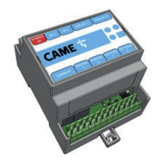
Page 4: Description Of Parts
CAME keypad connection terminal block (2 connections for SELT or S5000/S7000 accessories) ACS01 module connection terminal block (CAN bus) End-of-line jumper Input LEDs CL CH G B1 A1 B2 A2 G S1 G S2 Page 4 - FA01889-EN - 09/2022 - © CAME S.p.A. - -... -
Page 5: Technical Data
0 - 50 °C Humidity 0 - 90%, no condensation allowed Typical installation cabinet Electrical cabinet according to local electrical directives Module type Length (mm) Width (mm) Height (mm) ACS-EM 58,5 Page 5 - FA01889-EN - 09/2022 - © CAME S.p.A. - -... -
Page 6: Electrical Connections
. When the module is powered up, the LED lights up. + - + - + - NC C NO NC C NO CL CH G B1 A1 B2 A2 G S1 G S2 Page 6 - FA01889-EN - 09/2022 - © CAME S.p.A. - -... - Page 7 Connecting to the ACS01 module Connect the ACS-EM to the ACS01 module via a CAN bus to allow communication with the access-control system. CL CH G B1 A1 B2 A2 G S1 G S2 B1 A1 B2 A2 G S1 G S2 Close the end-of-line jumper on the last ACS-EM module connected.
-
Page 8: Inputs And Outputs
IN 2 RELAY 1 RELAY 2 RELAY EXPANSION MODULE KEYPAD 1 KEYPAD 2 BADGE 1 BADGE 2 CL CH G B1 A1 B2 A2 G S1 G S2 Page 8 - FA01889-EN - 09/2022 - © CAME S.p.A. - -... - Page 9 Model Transponder Module port 1 Module port 2 DIP confi guration connection connection connection 001TSP00 Red cable n.a. Black cable SELRxNDG, SELRxBDG 1,2,3 = OFF 4 = ON Page 9 - FA01889-EN - 09/2022 - © CAME S.p.A. - -...
-
Page 10: Connection Examples
CAME CONTROL BOARD ACS01 YOUR ACCESS CONTROL SYSTEM ACS-EM G CLCH − LOCK − − POWER SUPPLY ACS-EM CAME CONTROL BOARD POWER SUPPLY − − +24 V − Page 10 - FA01889-EN - 09/2022 - © CAME S.p.A. - -... - Page 11 CONFIGURATION Once the connections have been made, run cloud confi guration to assign the ACS-EM to the chosen ACS01 module. Go to www.came.io and enter your login details. Confi guration is performed online. Use an up-to-date internet browser. Page 11 - FA01889-EN - 09/2022 - © CAME S.p.A. - -...
- Page 12 From the [Site overview] screen, choose the desired [Site]. Page 12 - FA01889-EN - 09/2022 - © CAME S.p.A. - -...
- Page 13 Select [Add new module] and complete the following fi elds. In the [Name] fi eld, enter a name for the expansion module. Next use the dropdown menus to select the [ACS01 module] you want to associate the ACS-EM with, the [Connection method] and the [Port].
- Page 14 RELAY 1 RELAY 2 SN: XXXXXX XXXXXXX EXPANSION MODULE KEYPAD 1 KEYPAD 2 BADGE 1 BADGE 2 CL CH G B1 A1 B2 A2 G S1 G S2 Page 14 - FA01889-EN - 09/2022 - © CAME S.p.A. - -...
- Page 15 Page 15 - FA01889-EN - 09/2022 - © CAME S.p.A. - -...
- Page 16 Via Martiri della Libertà, 15 31030 Dosson di Casier Treviso – Italy Tel. (+39) 0422 4940 Fax (+39) 0422 4941 © CAME S.p.A. - The contents of this manual may be changed at any time and without notice. Translation of the original instructions...
Need help?
Do you have a question about the ACS-EM and is the answer not in the manual?
Questions and answers