
Related Manuals for CAME GLT40AOS


Summary of Contents for CAME GLT40AOS
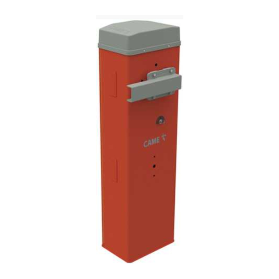
- Page 1 Automatic road barriers FA01748-EN GLT40AOS GLT40ROS GLT40ACS GLT40AX4 English INSTALLATION MANUAL...
- Page 2 DEVICE MANUAL RELEASE Releasing the device may be dangerous for the user, if the boom fastening has been damaged or if the boom is no longer intact, as the result of an accident or installation error. In these cases, the tensioned springs no longer guarantee that the boom is balanced. The boom may suddenly rotate when being released. Manual release may cause the operator to move in an uncontrolled manner due to a mechanical fault or an imbalance.
- Page 3 • The product, in its original packaging supplied by the manufacturer, must only be transported in a closed environment (railway carriage, containers, closed vehicles). • If the product malfunctions, stop using it and contact customer services at https://www.came.com/global/en/contact-us or via the telephone number on the website.
-
Page 4: Dismantling And Disposal
DISMANTLING AND DISPOSAL CAME S.p.A. employs an Environmental Management System at its premises. This system is certified and compliant with the UNI EN ISO 14001 standard to ensure that the environment is respected and safeguarded. Please continue safeguarding the environment. At CAME we consider it one of the fundamentals of our operating and market strategies. - Page 5 (**) The average product life specified should be understood purely as an indicative estimate. It applies to normal usage conditions and where the product has been installed and maintained in compliance with the instructions provided in the CAME technical manual. The average product life is also affected, including significantly, by other variables such as, but not limited to, climatic and environmental conditions.
-
Page 6: Description Of Parts
Description of parts Barrier Cover Lever arm Gear motor with encoder Boom anchoring plate Power supply terminal board Intermediate plate Line fuse Fastening flange Anchoring plate DIR/DXR photocell holes Anchoring bracket Lock for release Boom profile end cap Cabinet Spring anchoring pin Inspection hatch 001G04060 - Molla di bilanciamento Ø... -
Page 7: Control Board
Terminal board for power supply to the control board Terminal board for connecting the keypad selector Motor fuse Terminal board for connecting the transponder selector switch Connector for CAME KEY* Terminal board associated with the RSE_1 connector for paired, alternate or Memory Roll card connector CRP connection... - Page 8 Size max. 4000 Cable types and minimum thicknesses Cable length (m) up to 20 from 20 to 30 Power supply 230 V AC 3G x 1.5 mm² 3G x 2.5 mm² Power supply 120 V AC 3G x 1.5 mm² 3G x 2.5 mm²...
-
Page 9: Installation
INSTALLATION The following illustrations are examples only. The space available for fitting the operator and accessories varies depending on the area where it is installed. It is up to the installer to find the most suitable solution. In case of manual handling, have one person for every 20 kg that needs hoisting; for non-manual handling, use proper hoisting equipment in safe conditions. When the operator is being fixed in place, it may be unstable and overturn. - Page 10 Fill the hole with soil around the concrete block. Remove the nuts from the screws. Thread the electrical cables into the tubes so that they protrude by about 1500 mm. Preparing the barrier With the inspection hatch open, the operator does not work.
- Page 11 Fastening the barrier...
-
Page 12: Boom Installation
Changing the boom opening direction Boom installation Fix the flange and the intermediate plate to the anchoring plate with four screws leaving them loose. Fit the boom into the fastening flange. - Page 13 Tighten the screws using a torque wrench and a torque of 20 Nm. Choosing the hole for fixing the balance spring Passage width clearance (m) 2,00 < 2,25 2,25 < 2,75 2,75 < 3,25 3,25 < 3,50 3,50 < 3,75 3,75 <...
- Page 14 Assembling the balance spring Release the gearmotor. ① Hex-head screw M12 x 120 ② Position the boom vertically. Top spring attachment Lock the gearmotor ③ Bushing Ø13.8 4 5 6 Assemble the anchoring pin and fix it on the lever arm. ④...
- Page 15 Lubricate the spring when it is fully extended.
- Page 16 Balancing the boom Release the gearmotor. Lock the gearmotor Manually turn the spring to increase or reduce the traction. The boom should Check the proper working state of the spring. When the boom is vertical, the stabilise at 45°. spring is not taut. When the boom is horizontal, the spring is taut. Fasten the locknut.
- Page 17 Determining the travel end points with mechanical limit switches Check that the boom is parallel to the road surface when it is in the closed position and at about 89° when it is in the open position. Correct the boom’s horizontal position Release the gearmotor.
- Page 18 Correct the boom’s vertical position Release the gearmotor. Open the inspection hatch. Turn the mechanical stop until you reach the desired boom position. Fasten the mechanical stop with a locknut. Lock the gearmotor ~1° ~89°...
-
Page 19: Electrical Connections
ELECTRICAL CONNECTIONS Passing the electrical cables Connect all wires and cables in compliance with the law. The electrical cables must not touch any parts that may overheat during use (such as the motor and transformer). Make sure that the moving mechanical parts are suitably far away from the wiring. Power supply Make sure the mains power supply is disconnected during all installation procedures. - Page 20 Maximum capacity of contacts The total power of the outputs listed below must not exceed the maximum output power [Accessories] Device Output Power supply (V) Maximum power (W) Accessories 10 - 11 24 AC Flashing beacon 10 - E1 24 AC Passage-open warning light 10 - 5 24 AC...
-
Page 21: Signalling Devices
Signalling devices Additional light It increases the light in the manoeuvring area. See function [F18]. Additional flashing beacon It flashes when the operator opens and closes. See function [F18]. Operator status warning light It notifies the user of the operator status. See function [F10]. - Page 22 DIR / DELTA-S photocells DIR / DELTA-S photocells Standard connection Connection with safety test Multiple photocell pairs can be connected. Multiple photocell pairs can be connected. See function [F5] Safety devices test. 10 11 E1 TS 1 3 3P 4 2 CX CY CZ 10 11 E1 TS 1 3 3P 4...
-
Page 23: Getting Started
PROGRAMMING Programming button functions ESC button The ESC button is used to perform the operations described below. Exit the menu Delete the changes Go back to the previous screen < > buttons The <> buttons are used to perform the operations described below. Navigate the menu Increase or decrease values ENTER button... - Page 24 CY input Associate a function with the CY input. OFF (Default) C1 = Reopen while closing (photocells) C4 = Obstacle standby (photocells) C5 = Immediate closure at the travel end during opening C7 = Reopen while closing (sensitive edges) C9 = Immediate closure at the travel end during opening with obstacle standby during closure C10 = Immediate closure during opening with obstacle standby during closure (NO contact) C11 = Immediate closure during opening with obstacle standby during closure (NC contact) C13 = Reopen while closing, with immediate closure once the obstruction has been removed, even if the boom is not in motion...
- Page 25 Sensor type Choose the type of access device. 1 = Keypad (Default) 0 = Transponder LED strip light management Choose the operating mode for the LED strip light. 0 = bi-colour LED strip light (default) 1 = White LED strip light Light E1 Choose the type of device connected to output E1.
- Page 26 Configure the connector connections on RSE1 and RSE2. If an RSE card – configured for paired connections – is plugged into the RSE_1 connector, use the RSE_2 connector for remote connection (CRP). In this case, a CAME KEY cannot be connected. 1 = Paired...
- Page 27 Configure maintenance Set the number of manoeuvres the operator can perform before a maintenance warning signal is generated. The warning is displayed as an [SEr] message and signalled by 3 + 3 flashes every hour on the device connected to the 10-5 output. OFF (Default) 1 to 999 (1 = 1000 manoeuvres) Pre-flashing...
- Page 28 Remove user Remove one of the registered users. OFF (Default) No. 1 > 250 Use the arrows to choose the number associated with the user you want to remove. Alternatively, the control device associated with the user you want to remove can be activated. Press ENTER to confirm.
-
Page 29: Forgotten Password
Manoeuvre counter View the number of total or partial operator manoeuvres (after maintenance). The number of manoeuvres is the number shown multiplied by 1000. Tot = total manoeuvres Manoeuvres performed since the operator was installed. Par = partial manoeuvres Under the [Par] parameter, press the ENTER key to reset the number of partial manoeuvres. [Clr] will appear on the screen to confirm deletion. -
Page 30: Final Operations
FINAL OPERATIONS... -
Page 31: Operating Modes
PAIRED OPERATION Two connected operators are controlled with one command. Electrical connections Connect the two electronic boards with a UTP CAT 5 cable. Fit an RSE card on both control boards, using the RSE_1 connector. Connect up the electrics for the devices and accessories. For information on connecting the electrics for the devices and accessories, please see the “ELECTRICAL CONNECTIONS”... -
Page 32: Alternate Operation
ALTERNATE OPERATION The first barrier opens, the vehicle passes, the first barrier closes, the second barrier opens, the vehicle passes and the second barrier closes. Electrical connections Connect the two electronic boards with a UTP CAT 5 cable. Fit an RSE card on both control boards, using the RSE_1 connector. Connect up the electrics for the devices and accessories. - Page 33 ONLY OPEN command (2-3) on barrier B OPEN-CLOSE command (2-7) on barrier A or B for emergency opening...
- Page 34 MCBF Models LT/LS Standard boom L = 4 m 1.500.000 Skirt -20% Mobile foot -20% Articulated joint -20% The MCBF value relates to the barrier only and does not refer to any applicable accessories. The GARD LT barrier has been designed to perform up to 1.5 million cycles. Thanks to its 24V DC motor, it is extremely reliable and requires very little maintenance.
-
Page 35: Error Messages
ERROR MESSAGES Adjustment error Encoder failure error Service test failure error Operating time error Open release-hatch error Obstacle detected during closing Obstacle detected during opening The maximum number of obstacles detected consecutively has been exceeded No line voltage Serial communication error Incompatible transmitter error Open SLAVE-motor hatch error NOTICES... - Page 36 AFFIX THE PRODUCT LABEL FROM THE BOX HERE CAME S.p.A. Via Martiri della Libertà, 15 31030 Dosson di Casier Treviso – Italy Tel. (+39) 0422 4940 Fax (+39) 0422 4941...
Need help?
Do you have a question about the GLT40AOS and is the answer not in the manual?
Questions and answers