
Related Manuals for CAME ACS01


Summary of Contents for CAME ACS01
- Page 1 Access control system FA01815-EN ACS01 YOUR ACCESS CONTROL SYSTEM ACS01 Quick guide English...
-
Page 2: General Precautions
5 steps for confi guring ACS01 ① Connect ACS01 to a PoE switch with an Internet connection. ② Go to came.io and create an account, or log in if an account has already been created. ③ Create a site on came.io ④... -
Page 3: Technical Requirements
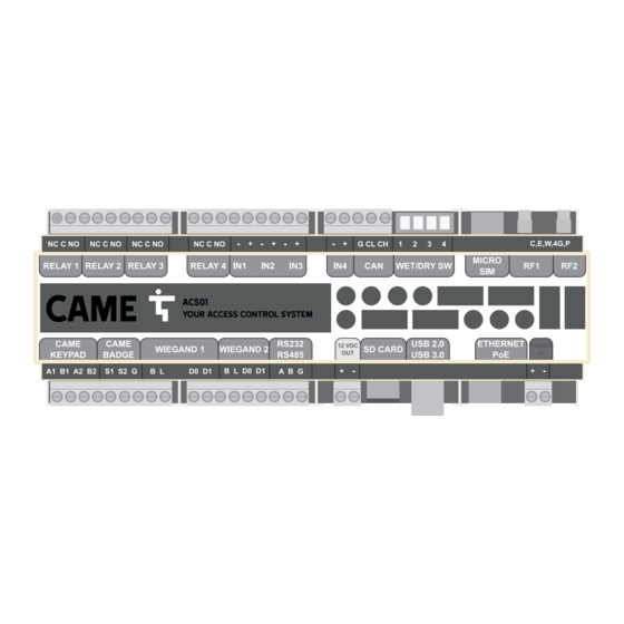
- Download >30Mbit/s; - Upload: >5Mbit/s; - Latency: 40ms; Ports for communication with the Cloud: - 443 (out): for communication with came.io UDP/TCP; - 4040 (out): for communication with mqtt.bluecherry.io UDP/TCP; - 123 (out on UDP): for NTP communication with: 147.135.207.214 93.94.88.51... - Page 4 DESCRIPTION OF PARTS AND TECHNICAL SPECIFICATIONS IN 4 IN 3 IN 2 IN 1...
- Page 5 Outputs: 4 relays can switch max. 3A to 24V DC 4 inputs (power up to 24V AC/DC) CAN-bus: enables communication with CAME BPT systems or expansion modules Microswitches to select wet or dry inputs. ON = dry contact (without power); OFF contact = wet (with power)
- Page 6 LED legend C E W 4G P Blue Cloud LED Green Ethernet Green Wi-Fi LED Red Power LED STATUS Green 4G LED OFF / Not Solid installed NO connection Quick fl ash Quick fl ash Quick fl ash Quick fl ash Solid Blinking 2x fast NOT connected...
- Page 7 2x1 mm2 wet contact 12-24V AC/DC or dry contact, Inputs 2x1 mm2 selectable by DIP- switch 900 total cable length Protocol: BPT, CAME BPT, CAN-Bus 3x1 mm2 250 maximum section termination 120Ω length CAME keypad 2x0,75 mm2 CAME transponder 2x0,75 mm2...
-
Page 8: Network Connection
Ethernet / PoE network connection Connect the Ethernet/PoE port of the module to the network. In PoE connection, the ACS01 receives power via the Ethernet cable. Connecting the power cable is optional. When no PoE is available, power the ACS01 locally... - Page 9 Wi-Fi connection Connect the antennas provided either directly on the control board or via a cable. ACS01 4G connection Insert the SIM card in the specifi c slot. Connect the antennas provided either directly on the control board or via a cable.
-
Page 10: Connecting The Power Supply
Connecting the power supply The ACS01 can be powered in two ways: 1. Ethernet (PoE) - preferable( 2. Electrical connections for 12V or 24V AC/DC( The red LED is stable when there is power. Both the power supply and the PoE can also be connected. The PoE will always be used as the primary power supply. - Page 11 CONFIGURATION - CLOUD PORTAL First access to the Cloud To access the software, the module needs to be connected to the chosen network. See "How to connect to the network". Confi guration is performed online. Use an up-to-date internet browser.
- Page 12 Go to www.came.io and click on [Create account] to create an account. Fill in all the required fi elds and click on [Create account]. The user will receive an email at the email address entered when creating an account. Click on the link in the email to activate the account.
- Page 13 Module claim Click on to associate an ACS01 module with the desired site. Scroll down to [Devices] and click on [Associate device].
- Page 14 Name the device. Enter the ID in the relevant fi eld. Be careful with capital letters. The module ID has 26 digits. Go back to the main page and click on [Open site] to start confi guring the module.
- Page 15 CONFIGURATION - SITE From the top menu it is possible to access the site confi guration categories. To access [Manual Control] and [Dashboard], click on [Overview]. To access [Manage Zones], [Manage Passages], [Manage Schedules] and [Manage Anti-Passback], click on [Access Control].
- Page 16 Passages...
- Page 17 Select the reader type from the dropdown menu. Select the connection type. Select the corresponding port. For more information on wiring readers, see "How to connect CAME components". Click on [Add to passage] to save.The reader has been added to the [Reception].
-
Page 18: Users And Groups
To view the operator status from the passage image, go to [Overview - Manual control]. Users and groups Groups Click on [Users] and select [Manage groups]. Click on [Add new group]. Name the group . If required, set the maximum number of users allowed in the group. To add zones to which users in this group have access, select a zone from the dropdown list and click [+]. - Page 19 Users Select [Users] and click on [Manage users]. Click on [Add new user]. To add a temporary user, click [Yes] and enter the start and end date when this user will be active. Enter all required data. The [Position] is where the badge will be used for the fi rst time. For example, if visitors receive their badge at reception, the position will be [Reception].
- Page 20 Add a new [Badge] by entering the badge number in the relevant fi eld. Be careful with capital letters. The badge number can be found on the badge itself. Click [+] to save and assign this badge to the user. A user may have several badges.
- Page 22 Overview Click on [Overview - Dashboard]. The [Dashboard] provides an overview of all the people inside the building, in a certain zone, all saved badges, etc.
- Page 24 CAME S.p.A. Via Martiri della Libertà, 15 31030 Dosson di Casier Treviso - Italy Tel. (+39) 0422 4940 Fax (+39) 0422 4941...
Need help?
Do you have a question about the ACS01 and is the answer not in the manual?
Questions and answers