Table of Contents
Advertisement
Advertisement
Table of Contents

Related Manuals for AnyTone AT-318UV


Summary of Contents for AnyTone AT-318UV
- Page 2 AT-318UV DUAL BAND HANDHELD RADIO INSTRUCTION MANUAL...
-
Page 4: Thank You
FM radio functions, etc.. It is a meticulous build functional and Multi frequency band radio for radio amateur. MODELS APPLY TO THIS MANUAL AT-318UV FM Transceiver Programming software: QPS318UV_1.01 PROGRAM CAUTIONS When programming the transceiver, read the factory initial data first, then rewrite the frequency and signaling... - Page 5 CAUTIONS transceiver is excellent designed with advanced technology. The following tips will be helpful for you in performing your obligation under warranty and understanding the safety of transceiver usage. 1.Keep the transceiver and accessories away from children. 2.Please do not try to open or modify the transceiver without permission, non-professionals operation may also cause damage.
-
Page 6: Table Of Contents
TABLE OF CONTENTS UNPACKING ........................................ 01 Supplied Accessories ..................................01 STANDARD ACCESSORIES/ADDITIONAL ACCESSORIES ................02 Standard Accessories ..................................02 Additional Accessories ..................................02 BATTERY INFORMATION ................................. 03 Charging Operation ....................................03 Battery Charger Type ................................... 03 Notice for Charging Battery ................................ - Page 7 TABLE OF CONTENTS Receiving ........................................12 Transmitting ......................................12 Emergency Alarm ....................................13 Side Key [PF1]/[PF2] function instruction ..........................13 MONI Key Function ....................................14 VFO Frequency Scanning Limited ............................... 14 Turn On/Off FM Radio ..................................14 CTCSS/DCS Setup ....................................15 CTCSS/DCS Scan ....................................
-
Page 8: Unpacking
UNPACKING Please carefully unpack the transceiver. We recommend that you identify the items listed in the following table before discarding the packing material. If any items are missing or have been damaged during shipment, please contact with dealers immediately. Supplied Accessories Item Number Quantity... -
Page 9: Standard Accessories/Additional Accessories
STANDARD ACCESSORIES/ADDITIONAL ACCESSORIES Standard Accessories Antenna* Li-ion Battery Battery Charger AC Adaptor Belt Clip Instruction QPS-01 Manual QA11UV QB-43L QBC-42L BC06 155/435MHz *1.Note: For frequency band of antenna, please refer to label indicated in the bottom of the antenna. Additional Accessories USB Programming Programming Software Earphone... -
Page 10: Battery Information
BATTERY INFORMATION Charging Operation The battery is not charged at the factory, please charge it before use. Charge the battery for the first time after purchase or extended storage (more than 2 months) may not bring the battery to its normal operating capacity. -
Page 11: How To Charge
BATTERY INFORMATION ▲ Do not recharge the battery if it is already fully charged. This may shorten the life of the battery or damage the battery. ▲ Do not charge the battery or transceiver if it is damp. Dry it before charging to avoid danger. WARNING: When keys or ornamental chains and other electric metals contact with the battery terminals, the battery may cause damage or hurt bodies. -
Page 12: Preparation
PREPARATION Installing / Removing the Battery ■ Installing the Battery Lay the battery to face the back of the radio. Press the button of battery, the latch in button of transceiver locks will release. After hearing a "click" sounds, the battery has been locked. ■... -
Page 13: Installing/Removing The Belt Clip
PREPARATION Installing / Removing the Belt Clip ■ Installing the Belt Clip: Place the belt clip to the grooves on the back of the transceiver, and then clockwise screw it. ■ Removing the Belt Clip: Anticlockwise turn the screws to remove the belt clip. Installing the Additional Speaker/ Microphone (Optional) Unveil the MIC-SP jack cover and then insert the Speaker/Microphone plug into MIC-SP jack. -
Page 14: Getting Acquainted
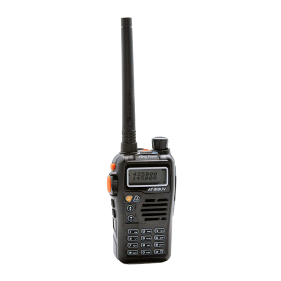
GETTING ACQUAINTED LCD Display On LCD display screen, you will see various icons which stand for the selected functions and sometimes you may forget the meaning of them. Here you will find the following table extremely useful. Frequency VOX Function Reverse Offset Frequency Scan Skip... - Page 15 GETTING ACQUAINTED ESC/M...
- Page 16 GETTING ACQUAINTED Antenna Lamp Power / Volume Switch Rotate it clockwise to turn on transceiver, rotate it anticlockwise until heard "click" to turn off the transceiver. When transceiver is power on, rotate it clockwise to increase volume, anticlockwise to reduce volume. LCD display Displays current frequency/channel and operations Speaker...
-
Page 17: Basic Operations
BASIC OPERATIONS Turn the Radio On & OFF Under power-off state, please turn [POWER]/[VOLUME] clockwise to turn on the transceiver. The transceiver will announces prompt tone and displays the current channel on screen. Under power-on state, please turn [POWER]/[VOLUME] anticlockwise till hearing "Click"... -
Page 18: Switch Between Channel Mode And Vfo Mode
BASIC OPERATIONS Switch between Channel mode and VFO mode Under standby state, press key to set main band as Channel mode or frequency mode(VFO). Channel Adjusting When transceiver in Channel mode or FM radio channel mode, rotate to adjust channel. Press to enter the downward channel, Press to enter the upward channel. -
Page 19: Fm Channel Searching
BASIC OPERATIONS 2. Enter the desired frequency by keypad. In VFO or FM VFO mode, you can directly input frequency by keypad. NOTE: The frequency input of main channel or FM radio is relevant to the stepping and transceiver frequency range. If frequency setup is beyond range or not matching with step size, the input is unavailable. Under the FM radio mode, the frequency step size input by numeric keys is 100k. -
Page 20: Emergency Alarm
BASIC OPERATIONS ensure it is not busy, press [PTT] key and talk to speaker. Please keep the distance between mouth and speaker to be 2.5-5CM, speak in normal tone to get the best acoustic fidelity. NOTE: When press and hold PTT key, transceiver is transmitting if the red LED light is on, release [PTT] key to receive calls. -
Page 21: Moni Key Function
BASIC OPERATIONS MONI Key Function 1.Squelch off: Press [MONI] key, squelch is not mute, you can hear background noise. Press [MONI] again, squelch is mute. 2.Monetary Squelch off: Press [MONI] key, squelch is not mute, you can hear background noise. Release [MONI] again, squelch is mute. -
Page 22: Ctcss/Dcs Setup
BASIC OPERATIONS press key to turn off FM radio and return to transceiver state. Re-start transceiver also can exit FM radio function. CTCSS/DCS Setup Under standby state, press key, the top left corner of LCD displays " " icon, press key, LCD displays "CT"... -
Page 23: Offset Frequency Direction Setup
BASIC OPERATIONS Offset Frequency Direction Setup Under standby state, press key, the top left corner of LCD displays " " icon, press key to choose offset frequency direction. There are 3 options, Positive offset, Minus offset, shut off offset. 1. (+) Positive offset: Indicates TX frequency is higher than RX frequency. When enable reverse function, the RX frequency is higher than TX frequency. -
Page 24: Channel Scan Skip
BASIC OPERATIONS 2. Channel Scan Under channel mode, this function is used for monitoring signal of each channel in this mode. Press numeric key or key to exit. NOTE: ▼ Frequency scan is of all bands scan, it scans upwards as your STEPPING setting. ▼... -
Page 25: Tx Power Selection
BASIC OPERATIONS to set arrow directed channel as frequency reverse, repeat above operation to turn off frequency reverse. 1. When LCD displays "R" icon, it means current arrow directed channel open the frequency reverse function, the TX frequency and RX frequency is interchanged, if CTCSS/DCS signaling is set, it will also interchange. -
Page 26: Keypad Lock
BASIC OPERATIONS 3. When current group displays "EMPTY", press key, the top left corner of LCD displays " " icon, press and hold key until transceiver emits "DU" beep, transceiver enters into DTMF edit state, LCD displays "___________", now you can enter desired DTMF data by keypad. 4. -
Page 27: Function Menu Setup
FUNCTION MENU SETUP Menu 1-13 of this transceiver are channel operations. Channel operations temporarily changed the functions of current channel. When power off or channel has been changed, the relevant setup will be erased. Only under VFO mode, the channel operations will be saved until next change. Menu 14-32 is background operation, it is valid for all channels, the relevant setup will be saved until next change. - Page 28 FUNCTION MENU SETUP No CTCSS/DCS Decode CTCSS/DCS 51 groups fixed CTCSS decode+1 group self- R-CDC 62.5HZ-254.1Hz+Self defined Decode defined CTCSS decode 000N-777I 1024 groups DCS decode No CTCSS/DCS encode/decode CTCSS/DCS 51 groups fixed CTCSS encode/decode + 1 group RT-CDC Encode/Decode 62.5HZ-254.1Hz+Self defined self-defined CTCSS encode/decode Synchronous...
- Page 29 FUNCTION MENU SETUP When current channel received matching RF Squelch mode signals, or matching optional signaling, or matching SIGNAL CT/TO setup CTCSS/DCS signaling, transceiver can hear the talking from the other party. Frequency step STEP 2.5K-50K 9 options in total size setup Wide / Narrow WIDE/NARROW...
- Page 30 FUNCTION MENU SETUP TX function is enabled in current channel TX OFF TX function is disabled in current channel BAND Band Limit ON/OFF Turn on/off band limit function FREQ Display sub band frequency or channel Sub band display DSPSUB VOLT Display current battery voltage setup Sub band display is disabled...
- Page 31 FUNCTION MENU SETUP When scanning matched signal, transceiver will 5ST-15ST stop scanning for 5-15seconds then resume. Scan Dwell Time SCAN When scanning matched signal, transceiver will stop Setup scanning, 2seconds after signal disappeared, then resume. When finished function setting or enter into FUNCT function menu, icon disappeared.
- Page 32 FUNCTION MENU SETUP VOLT Displays current battery capacity. CALL Call function. Self define PF1/ ALARM Emergency alarm function. PF2 key function SUBPTT Sub band PTT. LAMP Lamp No function.
-
Page 33: Display Mode Setup
FUNCTION MENU SETUP Display Mode Setup There are three kinds of display modes for optional. 1. Press [MONI] key to turn on radio, hold [MONI] key until transceiver emits beep. 2. Press key to choose No. 01 function item, it shows "DSP" on LCD. 3. - Page 34 FUNCTION MENU SETUP 2. Press key to choose No. 02 function item, it shows "RESTOR" on LCD. 3. Press enter into next menu, then press to select desired setting. OFF: No operations. FACT: Resume all items to factory default, including channel and background settings.
-
Page 35: Technical Specification
TECHNICAL SPECIFICATION General Receiving Part VHF: 136~174MHz Wide band narrow band Frequency Range UHF: 400~480MHZ Sensitivity ( EX: 400~520MHz) ≤0.25μV ≤0.35μV (12dB SInAD) Channel Capacity 200 channels Adjacent Channel 25KHz (wide band) ≥65dB ≥60dB Channel Spacing Selecitvity 12.5KHz (narrow band) Intermodulation ≥60dB ≥60dB... -
Page 36: Trouble Shooting Guide
TROUBLE SHOOTING GUIDE Problem Corrective Action A.The battery may be exhausting. Recharge or replace the battery. No power B.The battery may not be installed correctly. Remove the battery and install it again. Battery power dies shortly after The battery life is finished. Replace the battery pack with a new one. charging.
Need help?
Do you have a question about the AT-318UV and is the answer not in the manual?
Questions and answers