
Related Manuals for AnyTone Dual Band FM Transceiver


Summary of Contents for AnyTone Dual Band FM Transceiver
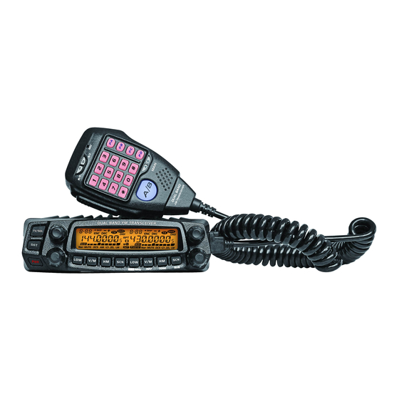
- Page 1 DUAL BAND FM TRANSCEIVER www.at-5888uv.com groups.yahoo.com/group/AT5888UV USER'S MANUAL REV 2.0 2/2013...
- Page 2 Nice Housing, Stoutness & Stability, Advanced and Reliable functions, Perfect & Valuable. Approval. Dual Band mobile radio especially designs for drivers and it pursues company philosophy of innovation and practicality. NOTE Dual Band Mobile Radio Applicable Software: QPS5888UV_S1 www.at-5888uv.com Model Apply To This Manual: Dual Band Mobile Radio...
- Page 3 The transceiver is a ruggedly-built, personal injury, or transceiver damage: high quality Dual band FM transceiver providing 50 Watts of Do not attempt to configure your transceiver while driving,it power output on the VHF band and 40 Watts on the UHF band. It is dangerous.
-
Page 4: Table Of Contents
CONTENTS New and Innovative Features ...........1 High/Mid/Low Power Switch ..........13 Frequency Range ..............1 Frequency Reverse ...............13 Supplied Accessories/Optional Accessories ......2 Band-width Selection ............13 Supplied Accessories ..............2 Home Channel ..............13 Optional Accessories ..............2 Hyper Memory channel ............13 Initial Installation ...............3 Dual Watch................14 Mobile installation ..............3 Emergency Alarm ..............14 Channel/Frequency Scan .............14... - Page 5 CONTENTS Squelch Mode Setup .............20 AM Function ................29 Compander ................21 Automatic AM function ............29 Scrambler Setup ..............21 VHF External speaker port ............30 Tone Burst (Pilot Frequency) ..........21 BEEP Volume control ............30 Keypad Mode Setup .............22 Talk Around................30 Keypad Lockout ..............23 Microphone speaker.............
-
Page 6: New And Innovative Features
New and Innovative Features Dual Band Mobile Radio has nice housing, stoutness & stability, advanced and reliable functions, perfect & valuable. This amateur mobile radio especially designs for drivers and it pursues company philosophy of innovation and practicality. More functions as follows: 758 memory channels, full duplex operation with independent volume and squelch controls 50 Watts of power output on the VHF band and 40 Watts on the UHF band with cross band repeat function. -
Page 7: Supplied Accessories/Optional Accessories
Supplied Accessories/Optional Accessories Supplied AcceSSoRieS After carefully unpacking the transceiver, identify the items listed in the table below. We suggest you keep the box and packaging. Transceiver Microphone (QHM-05) Mobile Mounting DC Power Cable with Hardware Kit for Bracket (with DTMF keyboard) Bracket (QMB-01) Fuse Holder(QPL-01) S-Washer... -
Page 8: Initial Installation
Initial Installation Determine the appropriate angle of the transceiver, using the 3 Mobile inStAllAtion screw hole positions on the side of the mounting bracket. To install the transceiver, select a safe, convenient location inside your vehicle that minimizes danger to your passengers and yourself while the vehicle is in motion. -
Page 9: Dc Power Cable Connection
Initial Installation Reconnect any wiring removed from the negative terminal. dc poweR cAble connection Locate the power input connector as close to the transceiver as possible. NOTE Mo bil e opeR At i on Black The vehicle battery must have a nominal rating of 12V. Never connect the transceiver to a 24V battery. - Page 10 Initial Installation When the ignition key is turned to ACC or ON(Start) position Connect the DC power cable to the regulated DC power supply with the radio turned off, the power switch illuminates. The and ensure that the polarities are correct. (Red: positive, illumination will be turned off when the ignition key is turned Black:negative).
-
Page 11: Antenna Connection
Initial Installation an impedance other than 50Ω reduces the efficiency of the antenna ReplA c i nG FuSeS system and can cause interference to nearby broadcast television If the fuse blows, determine the cause, then correct the problem. receivers, radio receivers, and other electronic equipment. After the problem is resolved, replace the fuse. -
Page 12: Accessories Connections
Initial Installation AcceSSoRieS connectionS Antenna[QCA-02] Microphone[QHM-04] exteR nA l SpeA keR If you plan to use an external speaker, choose a speaker with an impedance of 8 Ω. The external speaker jack accepts a 3.5 mm (1/8") mono (2-conductor) plug. External speaker[SP-02] SP-02 p c c onn ec tinG... -
Page 13: Getting Acquainted
Getting Acquainted FRont pAnel Function set Key In standby , press this key to enter function menu Press it to power On /Off the transceiver In standby press it to change H/L power for present Frequency Left【LOW】Key channel.Long press it to turn On/Off Reverse Function In standby, press it to switch between channel... -
Page 14: Rear Panel
Getting Acquainted ReAR pAnel NO. INDICATOR FUNCTION Displays the channel number and Menu number. Appears when current channel is priority channel Appears when current channel is set Scan Skip Appears when current channel has CTCSS Encode Appears when current channel has CTCSS Decode Appears when the Offset function is ON Appears while transmitting. -
Page 15: Microphone
Getting Acquainted MicRophone NO. KEY FUNCTION Increase frequency ,channel number or setting value. Decrease frequency, channel number or DOWN setting value. Press the PTT (Push-TO-Talk) key to transmit. Number Key Input VFO frequency or DTMF dial out etc. A/B band Choose left band or right band as Main band Band indicator The indicator light on for Main band. -
Page 16: Basic Operations
Press key to switch the transceiver ON, knob clockwise to increase frequency; the LCD displays "WELCOME ANYTONE", then counterclock-wise to decrease frequency. display current frequency or channel. E v e r y g e a r w i l l i n c r e a s e o r d e c r e a s e frequency by one step. -
Page 17: Switch Between Main Band And Sub Band
Basic Operations correspondent selector knob, the channel number flashes in this This transceiver can be set working on 2 UHF band or 2 VHF band. NOTE situation, the channel number will increase 10 channels by each gear of selector knob. Press microphone [ UP/DOWN ] key also able to adjust ReceiVinG the channel. -
Page 18: Shortcut Operations
Shortcut Operations Squelch leVel Setup In channel mode, this operation is for temporary use only NOTE This function is used to setup the strength of receiving signal, when the strength reach a certain level, the calling can be heard, otherwise, the FRequencY ReVeRSe transceiver will keep mute. -
Page 19: Dual Watch
Shortcut Operations for over 0.5 second, the radio prompts duAl wAtch "DU DU", and LCD displays "SKIP", and now In standby, hold key for over 0.5 second to enter Dual Watch the current channel is Scan Skip. mode. The radio will scan the channel in every 5 seconds. When the radio receives matching signal, it pause scanning until the signaling disappear. -
Page 20: Channel Delete
Shortcut Operations storage has data , the LCD will display the frequency, otherwise will display"----------") Press key, the LCD displays MEN-IN, channel copy completed. chAnnel delete I n s t a n d b y, h o l d k e y u n t i l t h e transceiver prompt DU, and channel number flashes. -
Page 21: General Setting
General Setting Basic operation steps for Function menu Turn the Main band selector knob to choose No. 02 menu. the LCD displays "ARS" Press key to enter function menu. Press the Main band selector knob to Turn the Main band selector knob to choose wanted function. enter function setup Press the Main band selector knob to enter function setup. -
Page 22: Vfo Band Lockout
General Setting cpu clock FRequencY chAnGe This function is auto-hidden in channel mode NOTE When any harmonic or image frequency in the CPU clock disturbs the working frequency, turn on this function will cut the disturbing VFo bAnd lockout Press key to enter function menu. -
Page 23: 5Tone Encode Select
General Setting Switch the Main band selector knob to choose wanted value 5tone encode Select DT: means DTMF signaling is added. Press key to enter function menu. 2T: means DTMF signaling is added. Turn the Main band selector knob to choose No. -
Page 24: Ctcss Decode Setup
General Setting Press the Main band selector knob or key to store value and Sub bAnd diSplAY Setup back to function menu. Press key or hold selector knob for Press key to enter function menu. over 0.5 second to store setup and exit. Turn the Main band selector knob to choose No. -
Page 25: Dtmf Encode Transmitting Time
General Setting When the selected group is empty, the dtMF encode tRAnSMittinG tiMe LCD displays '------" Press key to enter function menu. Press the selector knob to enter the DTMF signaling edit. The LCD Turn the Main band selector knob to display "-- -- -- -- -- --", the last character flashes. -
Page 26: Compander
General Setting Press the Main band selector knob or key to store value and Press key to enter function menu. back to function menu. Press key or hold selector knob for Turn the Main band selector knob to over 0.5 second to store setup and exit. choose No 18 menu. -
Page 27: Keypad Mode Setup
General Setting Press the Main band sel ector knob or key to store value and LCD displays DT means DTMF, displays 5T means 5TONE, displays 2T means 2TONE. back to function menu. Press key or hold selector knob for over 0.5 second to store setup and exit. -
Page 28: Keypad Lockout
General Setting Switch the Main band selector knob to choose wanted mode. time.The scan direction can be changed by corresponding channel selector knob.Note:To enable this function, the BAND R, lock the right band PTT. Only channel shall be programmed with CTCSS/DCS decode. able to transmit by left band. -
Page 29: Sub Band Mute Setup
General Setting Switch the Main band selector knob to choose wanted value. editinG chAnnel nAMe ON: Frequency Reverse is turn on, The TX and RX frequency will be After edit a name for a channel, if the display mode is channel name, exchanged, the CTCSS DCS signaling also will be exchanged if the will display the name edited in this menu. -
Page 30: Microphone Pa,Pb, Pc,Pd Key Setup
General Setting Switch the Mian band selector knob to choose wanted value. S-5: Able to hear the calling when the power meter reach 4 bar. S-9: Able to hear the calling when the power meter reach 8 bar. MANUAL: Auto storage is turn off. S-FULL: Able to hear the calling when the power meter reach full bar. -
Page 31: Priority Channel Scan
General Setting Switch the Main band selector knob to oFFSet FRequencY Setup choose wanted value. Press key to enter function menu. TIME: it pauses 5s once scanning a matching signal, then resume scan. Turn the Main band selector knob to BUSY: it pauses once scanning a matching signal, then resume scan choose No36 menu. -
Page 32: Busy Channel Lockout
General Setting buSY chAnnel lockout 5tone SelF id enquiRY With this function on, the transceiver will not transmit on a busy Press key to enter function menu. channel, to avoid disturbing other transceiver using same frequency. Switch the selector knob to choose No40 Once the channel is busy and you press PTT, the transceiver will beep as function. -
Page 33: Vfo Frequency Linkage
General Setting VFo FRequencY linkAGe cRoSS bAnd RepeAt Enable this function, the adjustment for any band of VFO frequency, Set the left band and right band as VHF (136~174MHz) and will bring same frequency change to both bands. Adjust one gear, the UHF(400~470MHz)then turn off this function will enable Cross Band frequency for both bands will increase or decrease one step size value. -
Page 34: Calling Record
General Setting choose wanted value. Press key to enter function menu. Turn the Main band selector knob to ON: turn on AM function. OFF: turn off AM function. choose No. 48 menu. The LCD displays Press the Main band selector knob or key to store value and "DIMMER"... -
Page 35: Vhf External Speaker Port
General Setting Switch the Main band selector knob to choose wanted value. Press the Main band selector knob or key to store value INT: Internal speaker, VHF and UHF band share one speaker and back to function menu. EXT: External speaker, the calling on VHF is only audible through the Press key or hold selector knob for over 0.5 second to external Dual Track speaker. -
Page 36: Microphone Operation
Microphone Operation when the LCD displays"-", means minus offset. This function is valid only when current channel set with offset frequency. NOTE DOWN Add or delete priority channel: In : Numeric Keys channel mode, press the key programmed UP/DOWN lock key as PRI function to set priority channel, when the LCD displays Main/Sub band switch current channel is set as priority channel. - Page 37 Microphone Operation REV: In standby, press the key programmed as "REV" function to turn- transmit pre-programmed DTMF, 2TONE, 5TONE code. on or turn off Frequency Revrse function. COMP: Compander function in standby , press the key programmed as HOME: HOME channel switch, in standby "COMP"...
-
Page 38: Cable Clone
Cable Clone This feature will copy the programmed data and parameters from the master unit to slave units. It copies the parameters and memory program settings. Use optional CP51 cloning cable, connect the cable between the data jacks on both master and slave. Press and hold right band key to power on, then hold this key until the LCD displays "CLONE". -
Page 39: Programming Software Installing And Starting
Programming Software Installing and Starting (in windows XP system) Double click ”QPS5888UV_S1 setup.exe“, then follow the installing instruction. inStAll uSb cAble dRiVeR pRoGRAMMe Pic1 Click start menu in computer, under “ALL PROGRAMS” menu, choose and click “USB To Com port” in QPS5888UV_S1 program, install “USB To Com port”... -
Page 40: Maintenance
Maintenance deFAult VAlue FoR FActoRY ReSuMe tRouble ShootinG Dual Band Mobile Radio Possible Causes and Potential Solutions Problem Left band Right band + and - polarities of power connection are (a) Power is on, nothing reversed. Connect red lead to plus terminal VFO frequency 145.15MHz 435.15MHz... -
Page 41: Specifications
Specifications General RX/TX:144~146MHz,430~440MHz TX: 144~146MHz (EXP:136~174MHz) Receiver (ETSI EN 301 783) 430~440MHz (EXP:400~490MHz) Wide band Narrow band RX: 108~180MHz (AM/FM) Sensitivity Frequency Range ≤0.25μV ≤0.35μV 220~260MHz (FM) (12dB SINAD) 400~490MHz (FM) Adjacent Channel ≥70dB ≥60dB 350~399.995MHz (FM) Selectivity Audio Response +1~-3dB(0.3~3KHz) +1~-3dB(0.3~2.55KHz) Number of Channels... -
Page 42: Attached Chart
Attached Chart 1024 GRoupS dcS code 51 GRoupS ctcSS tone FRequencY(hz) 62.5 77.0 91.5 107.2 127.3 151.4 167.9 183.5 199.5 225.7 254.1 Self 67.0 79.7 94.8 110.9 131.8 156.7 171.3 186.2 203.5 229.1 Define 69.3 82.5 97.4 114.8 136.5 159.8 173.8 189.9 206.5 233.6 71.9 85.4 100.0 118.8 141.3 162.2 177.3 192.8 210.7 241.8 74.4 88.5 103.5 123.0 146.2 165.5 179.9 196.6 218.1 250.3 The self defined CTCSS tone supports non standard codes. - Page 43 Attached Chart www.at-5888uv.com...
- Page 44 groups.yahoo.com/group/AT5888UV www.at-5888uv.com...
Need help?
Do you have a question about the Dual Band FM Transceiver and is the answer not in the manual?
Questions and answers