
Related Manuals for Daikin VRV 5 RXYA8A7Y1B


Summary of Contents for Daikin VRV 5 RXYA8A7Y1B
- Page 1 Installer and user reference guide VRV 5 heat pump RXYA8A7Y1B RXYA10A7Y1B RXYA12A7Y1B RXYA14A7Y1B RXYA16A7Y1B RXYA18A7Y1B RXYA20A7Y1B RYMA5A7Y1B...
-
Page 2: Table Of Contents
Table of contents Table of contents 1 About this document Meaning of warnings and symbols..........................2 General safety precautions For the installer ................................2.1.1 General ................................2.1.2 Installation site ............................... 2.1.3 Refrigerant — in case of R410A or R32......................2.1.4 Electrical ................................. - Page 3 Table of contents 10.2.6 Symptom: White mist comes out of a unit (Indoor unit) ................49 10.2.7 Symptom: White mist comes out of a unit (Indoor unit, outdoor unit)............49 10.2.8 Symptom: The user interface reads "U4" or "U5" and stops, but then restarts after a few minutes..49 10.2.9 Symptom: Noise of air conditioners (Indoor unit)..................
- Page 4 Table of contents 18.1.4 To select the piping size ..........................91 18.1.5 To select refrigerant branch kits ........................93 18.1.6 Installation limitations............................ 94 18.1.7 About the piping length..........................96 18.1.8 Single and multi-outdoor-unit combinations....................98 18.1.9 Multiple outdoor units: Possible layouts ....................... 100 18.2 Connecting the refrigerant piping ..........................
- Page 5 Table of contents 21.3 Using the leak detection function ..........................161 21.3.1 About automatic leak detection ........................161 21.3.2 To manually perform a leak detection......................161 22 Commissioning 22.1 Overview: Commissioning .............................. 163 22.2 Precautions when commissioning ..........................163 22.3 Checklist before commissioning.............................
-
Page 6: About This Document
Preparation of the installation, reference data,… Detailed step-by-step instructions and background information for basic and advanced usage Format: Digital files on https://www.daikin.eu. Use the search function find your model. The latest revision of the supplied documentation is published on the regional Daikin website and is available via your dealer. - Page 7 About this document WARNING Indicates a situation that could result in death or serious injury. WARNING: FLAMMABLE MATERIAL WARNING: MILDLY FLAMMABLE MATERIAL The refrigerant inside this unit is mildly flammable. CAUTION Indicates a situation that could result in minor or moderate injury. NOTICE Indicates a situation that could result in equipment or property damage.
-
Page 8: General Safety Precautions
WARNING Improper installation or attachment of equipment or accessories could result in electrical shock, short-circuit, leaks, fire or other damage to the equipment. ONLY use accessories, optional equipment and spare parts made or approved by Daikin unless otherwise specified. WARNING Make sure installation, testing and applied materials comply with applicable legislation (on top of the instructions described in the Daikin documentation). -
Page 9: Installation Site
General safety precautions In accordance with the applicable legislation, it might be necessary to provide a logbook with the product containing at least: information on maintenance, repair work, results of tests, stand-by periods,… Also, at least, following information MUST be provided at an accessible place at the product: ▪... - Page 10 General safety precautions WARNING Take sufficient precautions in case of refrigerant leakage. If refrigerant gas leaks, ventilate the area immediately. Possible risks: ▪ Excessive refrigerant concentrations in a closed room can lead to oxygen deficiency. ▪ Toxic gas might be produced if refrigerant gas comes into contact with fire. WARNING ALWAYS recover the refrigerant.
-
Page 11: Electrical
General safety precautions Then A siphon tube is NOT present Charge with the cylinder upside down. ▪ Open refrigerant cylinders slowly. ▪ Charge the refrigerant in liquid form. Adding it in gas form may prevent normal operation. CAUTION When the refrigerant charging procedure is done or when pausing, close the valve of the refrigerant tank immediately. - Page 12 General safety precautions WARNING ▪ ONLY use copper wires. ▪ Make sure the field wiring complies with the applicable legislation. ▪ All field wiring MUST be performed in accordance with the wiring diagram supplied with the product. ▪ NEVER squeeze bundled cables and make sure they do NOT come in contact with the piping and sharp edges.
- Page 13 General safety precautions Install power cables at least 1 meter away from televisions or radios to prevent interference. Depending on the radio waves, a distance of 1 meter may NOT be sufficient. NOTICE ONLY applicable if the power supply is three‑phase, and the compressor has an ON/ OFF starting method.
-
Page 14: Specific Installer Safety Instructions
Specific installer safety instructions 3 Specific installer safety instructions Always observe the following safety instructions and regulations. Installation site (see "17.1 Preparing the installation site" [ 82]) WARNING Follow the service space dimensions in this manual to install the unit correctly. See "27.1 Service space: Outdoor unit" [ 188]. - Page 15 Specific installer safety instructions DANGER: RISK OF ELECTROCUTION Do NOT leave the unit unattended when the service cover is removed. Mounting the outdoor unit (see "17.3 Mounting the outdoor unit" [ 88]) WARNING Fixing method of the outdoor unit MUST be in accordance with the instructions from this manual.
- Page 16 Specific installer safety instructions CAUTION Do NOT vent gases into the atmosphere. WARNING Any gas or oil remaining inside the stop valve may blow off the pinched piping. Failure to observe the instructions in procedure below properly may result in property damage or personal injury, which may be serious depending on the circumstances.
- Page 17 Specific installer safety instructions WARNING The appliance MUST be installed in accordance with national wiring regulations. CAUTION Do NOT push or place redundant cable length into the unit. WARNING ▪ If the power supply has a missing or wrong N-phase, equipment might break down.
-
Page 18: Instructions For Equipment Using R32 Refrigerant
Specific installer safety instructions "22 Commissioning" [ 163]) Commissioning (see WARNING Commissioning MUST be in accordance with the instructions from this manual. See "22 Commissioning" [ 163]. CAUTION Do NOT perform the test operation while working on the indoor units. When performing the test operation, NOT ONLY the outdoor unit, but the connected indoor unit will operate as well. - Page 19 65]. WARNING Make sure installation, servicing, maintenance and repair comply with instructions from Daikin and with applicable legislation (for example national gas regulation) and are executed ONLY by authorised persons. WARNING ▪ Take precautions to avoid excessive vibration or pulsation to refrigeration piping.
-
Page 20: For The User
For the user RYMA5+RXYA8~20A7Y1B Installer and user reference guide VRV 5 heat pump 4P749918-1 – 2023.12... -
Page 21: User Safety Instructions
User safety instructions 4 User safety instructions Always observe the following safety instructions and regulations. In this chapter General....................................Instructions for safe operation............................... 4.1 General WARNING If you are NOT sure how to operate the unit, contact your installer. WARNING This appliance can be used by children aged from 8 years and above and persons with reduced physical, sensory or mental capabilities or lack of experience and knowledge if... -
Page 22: Instructions For Safe Operation
4.2 Instructions for safe operation WARNING Make sure installation, servicing, maintenance, repair and applied materials follow the instructions from Daikin (including all documents listed in “Documentation set”) and, in addition, comply with applicable legislation and are performed by qualified persons only. In Europe and areas where IEC standards apply, EN/IEC 60335-2-40 is the applicable standard. - Page 23 User safety instructions CAUTION ▪ NEVER touch the internal parts of the controller. ▪ Do NOT remove the front panel. Some parts inside are dangerous to touch and appliance problems may happen. For checking and adjusting the internal parts, contact your dealer. CAUTION Do NOT operate the system when using a room fumigation-type insecticide.
- Page 24 User safety instructions CAUTION Do NOT insert fingers, rods or other objects into the air inlet or outlet. Do NOT remove the fan guard. When the fan is rotating at high speed, it will cause injury. CAUTION: Pay attention to the fan! It is dangerous to inspect the unit while the fan is running.
- Page 25 User safety instructions WARNING ▪ Do NOT pierce or burn refrigerant cycle parts. ▪ Do NOT use cleaning materials or means to accelerate the defrosting process other than those recommended by the manufacturer. ▪ Be aware that the refrigerant inside the system is odourless.
- Page 26 User safety instructions CAUTION Do NOT touch the heat exchanger fins. These fins are sharp and could result in cutting injuries. RYMA5+RXYA8~20A7Y1B Installer and user reference guide VRV 5 heat pump 4P749918-1 – 2023.12...
-
Page 27: About The System
About the system 5 About the system The VRV 5 uses R32 refrigerant which is rated as A2L and is mildly flammable. For compliance with the requirements for enhanced tightness refrigerating systems and IEC60335-2-40 the installer must take extra measures. For more information, "3.1 Instructions for equipment using R32 refrigerant" [ 18]. -
Page 28: System Layout
About the system NOTICE It is NOT allowed to cool technical rooms like server rooms and data centres, where year-round cooling is required. 5.1 System layout Your VRV 5 heat pump series outdoor unit can be one of following models: Model Description RXYA8~12... -
Page 29: User Interface
User interface 6 User interface CAUTION ▪ NEVER touch the internal parts of the controller. ▪ Do NOT remove the front panel. Some parts inside are dangerous to touch and appliance problems may happen. For checking and adjusting the internal parts, contact your dealer. -
Page 30: Operation
Operation 7 Operation In this chapter Before operation ..................................Operation range..................................Operating the system ................................7.3.1 About operating the system ..........................7.3.2 About cooling, heating, fan only, and automatic operation ................. 7.3.3 About the heating operation ..........................7.3.4 To operate the system (WITHOUT cool/heat changeover remote control switch) ..........7.3.5 To operate the system (WITH cool/heat changeover remote control switch)............. -
Page 31: Operating The System
Operation Cooling Heating Outdoor temperature –5~46°C DB –20~20°C DB –20~15.5°C WB Indoor temperature 21~32°C DB 15~27°C DB 14~25°C WB Indoor humidity ≤80% To avoid condensation and water dripping out of the unit. If the temperature or the humidity is beyond these conditions, safety devices may be put in action and the air conditioner may not operate. -
Page 32: To Operate The System (Without Cool/Heat Changeover Remote Control Switch)
Operation frost from the outdoor unit’s coil. During defrost operation the heating capacity on the indoor unit side will temporarily drop until defrosting is completed. After defrosting, the unit will regain its full heating capacity. In case of Then Multi-use models The indoor unit will continue heating operation at a (continuous heating) reduced level during defrost operation. -
Page 33: To Operate The System (With Cool/Heat Changeover Remote Control Switch)
Operation 7.3.5 To operate the system (WITH cool/heat changeover remote control switch) Overview of the changeover remote control switch FAN ONLY/AIR CONDITIONING SELECTOR SWITCH Set the switch to for fan only operation or to for heating or cooling operation. COOL/HEAT CHANGEOVER SWITCH Set the switch to for cooling or to heating... -
Page 34: To Use The Dry Program (Without Cool/Heat Changeover Remote Control Switch)
Operation ▪ The micro computer automatically determines temperature and fan speed (cannot be set by the user interface). ▪ The system does not go into operation if the room temperature is low (<20°C). 7.4.2 To use the dry program (WITHOUT cool/heat changeover remote control switch) To start 1 Press the operation mode selector button on the user interface several times and select... -
Page 35: Adjusting The Air Flow Direction
Operation NOTICE Do not turn off power immediately after the unit stops, but wait for at least 5 minutes. 7.5 Adjusting the air flow direction Refer to the operation manual of the user interface. 7.5.1 About the air flow flap Air flow flap types: ▪... -
Page 36: Setting The Master User Interface
Operation 7.6 Setting the master user interface 7.6.1 About setting the master user interface a Outdoor unit b SV unit c VRV DX indoor unit d User interface e Direct connection to VRV DX indoor unit When the system is installed as shown in the figure above, it is necessary to – for each subsystem –... - Page 37 Operation Type Description Two user interface control Two user interfaces control one indoor unit (in system case of group control system, one group of indoor units). The unit is individually operated. NOTICE Contact your dealer in case of changing the combination or setting of group control and two user interface control systems.
-
Page 38: Energy Saving And Optimum Operation
Energy saving and optimum operation 8 Energy saving and optimum operation Observe the following precautions to ensure the system operates properly. ▪ Adjust the air outlet properly and avoid direct air flow to room inhabitants. ▪ Adjust the room temperature properly for a comfortable environment. Avoid excessive heating or cooling. -
Page 39: Available Main Operation Methods
Energy saving and optimum operation 8.1 Available main operation methods Basic The refrigerant temperature is fixed independent from the situation. It corresponds to the standard operation which is known and can be expected from/ under previous VRV systems. Automatic The refrigerant temperature is set depending on the outdoor ambient conditions. As such adjusting the refrigerant temperature to match the required load (which is also related to the outdoor ambient conditions). -
Page 40: Maintenance And Service
Maintenance and service 9 Maintenance and service In this chapter Precautions for maintenance and service..........................Maintenance before a long stop period ..........................Maintenance after a long stop period ........................... About the refrigerant ................................After-sales service................................... 9.5.1 Recommended maintenance and inspection......................9.5.2 Recommended maintenance and inspection cycles ..................... -
Page 41: About The Refrigerant
Maintenance and service ▪ Clean air filters and casings of indoor units. Contact your installer or maintenance person to clean air filters and casings of the indoor unit. Maintenance tips and procedures for cleaning are provided in the installation/operation manuals of dedicated indoor units. -
Page 42: Recommended Maintenance And Inspection Cycles
Maintenance and service WARNING ▪ Do NOT modify, disassemble, remove, reinstall or repair the unit yourself as incorrect dismantling or installation may cause an electrical shock or fire. Contact your dealer. ▪ In case of accidental refrigerant leaks, make sure there are no naked flames. The refrigerant itself is entirely safe, non-toxic and mildly flammable, but it will generate toxic gas when it accidentally leaks into a room where combustible air from fan heaters, gas cookers, etc. - Page 43 Maintenance and service ▪ Power fluctuation is high (voltage, frequency, wave distortion, etc.) (the unit cannot be used if power fluctuation is outside the allowable range). ▪ Bumps and vibrations are frequent. ▪ Dust, salt, harmful gas or oil mist such as sulphurous acid and hydrogen sulfide may be present in the air.
-
Page 44: Troubleshooting
Troubleshooting 10 Troubleshooting If one of the following malfunctions occurs, take the measures shown below and contact your dealer. WARNING Stop operation and shut OFF the power if anything unusual occurs (burning smells etc.). Leaving the unit running under such circumstances may cause breakage, electrical shock or fire. -
Page 45: Error Codes: Overview
Troubleshooting Malfunction Measure The system operates but ▪ Check if air inlet or outlet of outdoor or indoor cooling or heating is unit is not blocked by obstacles. Remove any insufficient. obstacles and make sure the air can flow freely. ▪... - Page 46 Troubleshooting Main code Contents External protection device was activated The R32 sensor in one of the indoor units has detected a refrigerant leak The R32 sensor in one of the SV unit has detected a refrigerant leak. Safety system error (leak detection) EEPROM failure (indoor) Drain system malfunction (indoor/SV unit) Fan motor malfunction (indoor)
- Page 47 Troubleshooting Main code Contents SV unit damper malfunction Discharge temperature malfunction (outdoor) Abnormal suction temperature (outdoor) Refrigerant overcharge detection High pressure switch malfunction Low pressure switch malfunction Fan motor malfunction (outdoor) Ambient temperature sensor malfunction (outdoor) Discharge temperature sensor malfunction (outdoor) Suction temperature sensor malfunction (outdoor) De-icing temperature sensor malfunction (outdoor) or heat exchanger gas temperature sensor malfunction (outdoor)
-
Page 48: Symptoms That Are Not System Malfunctions
Troubleshooting Main code Contents External ventilation input error Centralised address duplication Malfunction in communication centralised control device - indoor unit Faulty wiring indoor/SV unit Auto address malfunction (inconsistency) Airflow rate below the legal limit (for EKEA/EKVDX) The error code is only shown on the user interface of the indoor unit where the error occurs. -
Page 49: Symptom: The Fan Direction Does Not Correspond To The Setting
Troubleshooting speed. This is to prevent cold air blowing directly on occupants of the room. The fan speed will not change even when another indoor unit is in heating operation, if the button is pressed. 10.2.5 Symptom: The fan direction does not correspond to the setting The fan direction does not correspond with the user interface display. -
Page 50: Symptom: Noise Of Air Conditioners (Indoor Unit, Outdoor Unit)
Troubleshooting 10.2.10 Symptom: Noise of air conditioners (Indoor unit, outdoor unit) ▪ A continuous low hissing sound is heard when the system is in cooling or defrost operation. This is the sound of refrigerant gas flowing through both indoor and outdoor units. -
Page 51: Relocation
Relocation 11 Relocation Contact your dealer to remove and reinstall the entire unit. Moving units requires technical expertise. RYMA5+RXYA8~20A7Y1B Installer and user reference guide VRV 5 heat pump 4P749918-1 – 2023.12... -
Page 52: Disposal
Disposal 12 Disposal This unit uses hydrofluorocarbon. Contact your dealer when discarding this unit. It is required by law to collect, transport and discard the refrigerant in accordance with the "hydrofluorocarbon collection and destruction" regulations. NOTICE Do NOT try to dismantle the system yourself: dismantling of the system, treatment of the refrigerant, oil and other parts MUST comply with applicable legislation. -
Page 53: Technical Data
Follow the steps below to consult the Energy Label – Lot 21 data of the unit and outdoor/indoor combinations. 1 Open the following webpage: https://energylabel.daikin.eu/ 2 To continue, choose: ▪ "Continue to Europe" for the international website. ▪ "Other country" for a country related site. -
Page 54: For The Installer
For the installer RYMA5+RXYA8~20A7Y1B Installer and user reference guide VRV 5 heat pump 4P749918-1 – 2023.12... -
Page 55: About The Box
About the box 14 About the box Keep the following in mind: ▪ At delivery, the unit MUST be checked for damage and completeness. Any damage or missing parts MUST be reported immediately to the claims agent of the carrier. ▪... -
Page 56: To Unpack The Outdoor Unit
About the box 14.1 To unpack the outdoor unit Remove the packaging material from the unit: ▪ Take care not to damage the unit when removing the shrink foil with a cutter. ▪ Remove the 4 bolts fixing the unit to its pallet. Note: This product is not designed for repacking. -
Page 57: Accessory Pipes: Diameters
About the box a General safety precautions b Installation manual and operation manual c Additional refrigerant charge label d Installation information sticker e Fluorinated greenhouse gases label f Multilingual fluorinated greenhouse gases label g Piping accessory bag 14.3 Accessory pipes: Diameters Accessory pipes Øa [mm] Øb [mm]... - Page 58 About the box 2 Remove the transportation stay (b) as shown in the figure below. (12.3 N·m) a Bolt b Transportation stay RYMA5+RXYA8~20A7Y1B Installer and user reference guide VRV 5 heat pump 4P749918-1 – 2023.12...
-
Page 59: About The Units And Options
About the units and options 15 About the units and options In this chapter 15.1 Identification label: Outdoor unit............................15.2 About the outdoor unit ................................15.3 System layout..................................15.4 Combining units and options..............................15.4.1 About combining units and options........................15.4.2 Possible combinations of indoor units........................ -
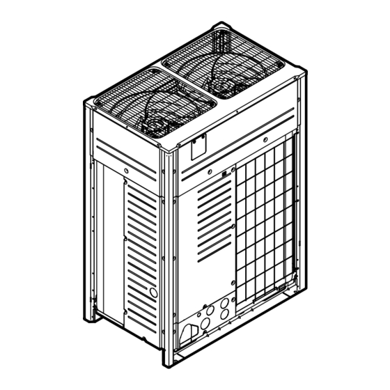
Page 60: About The Outdoor Unit
About the units and options 15.2 About the outdoor unit This installation manual concerns the VRV 5, full inverter driven, heat pump system. Model line up: Model Description RXYA8~12 Heat pump model, for single or multi-use RXYA14~20 Heat pump model, for single use (standalone unit) RYMA5 Heat pump model, only for multi-use and only for standard combinations... -
Page 61: Combining Units And Options
About the units and options a Heat pump outdoor unit b Safety valve unit (SV) c VRV direct expansion (DX) indoor unit d VRV direct expansion (DX) indoor unit (direct connection from outdoor to indoor) e Remote controller in normal mode f Remote controller in alarm only mode g Remote controller in supervisor mode (mandatory in some situations) h Centralised controller (optional) -
Page 62: Possible Combinations Of Outdoor Units
About the units and options 15.4.3 Possible combinations of outdoor units Possible standalone outdoor units Non-continuous heating RXYA8 RXYA10 RXYA12 RXYA14 RXYA16 RXYA18 RXYA20 Possible standard combinations of outdoor units ▪ RYMA5 units cannot be used as standalone outdoor units. ▪... - Page 63 About the units and options Description Model name Refnet joint KHRQ22M20TA (inch) KHRQ22M29T9 (inch) KHRA22M65T (inch) KHRQM22M20T (mm) KHRQM22M29T (mm) KHRAM22M65T (mm) For the selection of the optimal branching kit, please refer to "18.1.5 To select refrigerant branch kits" [ 93]. Outdoor multi connection piping kit Number of outdoor units Model name...
-
Page 64: About The Piping Connections
About the units and options 15.5 About the piping connections a Liquid piping b Equalising piping c Gas piping The VRV heat pump system has three piping connections. Depending on the type of application connection of the piping will vary: ▪... -
Page 65: Special Requirements For R32 Units
Special requirements for R32 units 16 Special requirements for R32 units In this chapter 16.1 Installation space requirements............................. 16.2 System layout requirements ..............................16.3 To determine the required safety measures ......................... 16.3.1 Overview: flowchart ............................... 16.4 Safety measures..................................16.4.1 No safety measure ..............................16.4.2 Alarm .................................. - Page 66 Special requirements for R32 units For more information about the SVS output, see "20.7 To connect the external outputs" [ 138]. Indoor unit installation NOTICE If one or more rooms are connected to the unit using a duct system, make sure air inlet AND outlet are connected directly to the same room by ducting.
- Page 67 Special requirements for R32 units Examples NOT OK Case Remote controller is not R32 safety system compatible Indoor units without remote controller are not allowed In case of one R32 safety system compatible remote controller, it should be the master and in the same room of the indoor unit.
-
Page 68: To Determine The Required Safety Measures
Special requirements for R32 units NOT OK Case In particular situations it is mandatory to install a remote controller at a supervised location In room: master remote controller in fully functional OR alarm only. In supervisor room: supervisor remote controller a Outdoor unit b SV unit c Indoor unit... - Page 69 Special requirements for R32 units Lowest underground floor All other floors No safety measure No safety measure Alarm + shut-off valve [SV unit] NOT allowed Alarm + natural ventilation m [kg] m [kg] [m²] [m²] m [kg] Lowest underground floor All other floors m [kg] Lowest underground floor...
- Page 70 Special requirements for R32 units Use the total amount of refrigerant in the system and the smallest area of the room in which the indoor unit is installed/conditioning to check which safety measure is required. Note: When "No safety measure" is required, it is still allowed to apply natural ventilation or alarm or shut-off valve (SV unit) if wanted.
- Page 71 Special requirements for R32 units SV unit Room area Required safety measure A=15 m²<40 m² Alarm + natural ventilation OR Alarm + shut-off valve (SV unit) No safety measure Alarm + shut-off valve [SV unit] Alarm + natural ventilation m [kg] m Total refrigerant charge in the system [kg] Minimum room area [m²] (a) Lowest underground floor (=Lowest underground floor) (b) All other floors (=All other floors)
-
Page 72: Overview: Flowchart
Special requirements for R32 units 16.3.1 Overview: flowchart Procedure to check required countermeasure for indoor unit Determine total amount of See Step 1 in above text refrigerant in the system. Total charge amount [kg] Determine the smallest area out of: - the room where an indoor unit is installed, - each of the rooms served by a ducted indoor unit installed in a different room... -
Page 73: Alarm
Special requirements for R32 units Note: For more information, see "21.1.9 Indoor unit field setting" [ 155]. 16.4.2 Alarm For installation of the remote controller, please refer to the installation and operation manual delivered with the remote controller. Each indoor unit must be connected with a R32 safety system compatible remote controller (e.g. -
Page 74: Natural Ventilation
Special requirements for R32 units Note: Depending on configuration, the remote controller is operable in three possible modes. Each mode offers different controller functionality. For detailed information about setting the operation mode of the remote controller and its function, please refer to the installer and user reference guide of the remote controller. - Page 75 Special requirements for R32 units The natural ventilation safety measure can be applied by following the steps below: Step 1 – Determine total room area, which is the total area of the space that has natural ventilation and the space in which the indoor unit is installed: The respective room area can be determined by projecting the walls, doors and partitions to the floor and calculating the enclosed area.
- Page 76 Special requirements for R32 units ≥ 20 mm ≥ 20 mm nvmin ≥ 50% A nvmin ≤ 100 mm Minimal natural ventilation area nvmin For the lower opening: It is not an opening to the outside The opening cannot be closed The opening must be ≥0.012 m²...
-
Page 77: Shut-Off Valves
Special requirements for R32 units 16.4.4 Shut-off valves In case shut-off valves are required as a safety measure, SV unit which has shut-off valves needs to be installed to reduce the amount of refrigerant leakage in to the room where the indoor unit is installed. For installation of the SV unit, refer to the installation and operation manual delivered with the SV unit. - Page 78 Special requirements for R32 units Area of installed/conditioned Maximum total indoor unit capacity class room [m²] 1 indoor unit per branch pipe 2~5 indoor units per branch pipe port port 40 m after 1 branch 90 m after 1 branch — — —...
- Page 79 Special requirements for R32 units Example VRV system serving three rooms via one SV unit. Room 1 (20 m²) is served by one indoor unit (32 class) connected to port A. Room 2 (42 m²) is served by two indoor units (2×50 class) connected to port B (no extension and liquid pipe size up has been done).
-
Page 80: Overview: Flowchart
Special requirements for R32 units 16.4.5 Overview: flowchart §16.4.1 §16.4.2 §16.4.3 §16.4.4 Shut-off valves No safety measure Alarm Natural ventilation Select the SV unit. Make field settings in the indoor unit Determine total room area (= total area of the accordingly. -
Page 81: Combinations Of Safety Measures
Special requirements for R32 units 16.5 Combinations of safety measures It is possible to combine indoor units with different safety measures (no safety measures, alarm and/or natural ventilation, alarm and shut-off valves) in the same VRV 5 system. Example a Heat pump outdoor unit b Safety valve unit (SV) c Indoor unit with no safety measure d Indoor unit with alarm safety measure... -
Page 82: Unit Installation
Unit installation 17 Unit installation WARNING The installation MUST comply with the requirements that apply to this R32 equipment. For more information, see "16 Special requirements for R32 units" [ 65]. In this chapter 17.1 Preparing the installation site ..............................17.1.1 Installation site requirements of the outdoor unit ....................17.1.2 Additional installation site requirements of the outdoor unit in cold climates ........... - Page 83 Unit installation INFORMATION Equipment meets the requirement for commercial and light-industrial location when professionally installed and maintained. CAUTION Appliance NOT accessible to the general public. Install it in a secured area, protected from easy access. This unit is suitable for installation in a commercial and light industrial environment. The outdoor unit is designed for outdoor installation only, and for the following ambient temperatures: Cooling...
- Page 84 Unit installation a Personal computer or radio b Fuse c Earth leakage protector d User interface e Indoor unit f Outdoor unit ▪ In places with weak reception, keep distances of 3 m or more to avoid electromagnetic disturbance of other equipment and use conduit tubes for power and transmission lines.
-
Page 85: Additional Installation Site Requirements Of The Outdoor Unit In Cold Climates
Unit installation ▪ In vehicles or vessels ▪ Where acidic or alkaline vapour is present Seaside installation. Make sure the outdoor unit is NOT directly exposed to sea winds. This is to prevent corrosion caused by high levels of salt in the air, which might shorten the life of the unit. - Page 86 Ambient indoor temperature Ambient outdoor temperature If the unit has to operate for 5 days in this area with high humidity (>90%), Daikin recommends to install the optional heater tape kit (EKBPH012TA or EKBPH020TA) to keep the drain holes free. RYMA5+RXYA8~20A7Y1B...
-
Page 87: Opening The Unit
Unit installation 17.2 Opening the unit 17.2.1 About opening the units At certain times, you have to open the unit. Example: ▪ When connecting the electrical wiring ▪ When maintaining or servicing the unit DANGER: RISK OF ELECTROCUTION Do NOT leave the unit unattended when the service cover is removed. 17.2.2 To open the outdoor unit DANGER: RISK OF ELECTROCUTION DANGER: RISK OF BURNING/SCALDING... -
Page 88: Mounting The Outdoor Unit
Unit installation 14~20 HP 6× NOTICE When closing the switch box cover, make sure that the sealing material on the lower back side of the cover is NOT caught and bent towards the inside (see figure below). a Switch box cover b Front side c Power supply terminal block d Sealing material... -
Page 89: To Install The Outdoor Unit
Unit installation ≥AB (mm) Minimum foundation a Anchor point (4×) 5~12 14~20 1076 1302 ▪ Fasten the unit in place using four foundation bolts M12. It is best to screw in the foundation bolts until their length remains 20 mm above the foundation surface. NOTICE ▪... -
Page 90: Piping Installation
Piping installation 18 Piping installation CAUTION "3 Specific installer safety instructions" [ 14] to make sure this installation complies with all safety regulations. In this chapter 18.1 Preparing refrigerant piping ..............................18.1.1 Refrigerant piping requirements ........................... 18.1.2 Refrigerant piping material ............................ 18.1.3 Refrigerant piping insulation.......................... -
Page 91: Refrigerant Piping Material
Piping installation 18.1.2 Refrigerant piping material ▪ Piping material: phosphoric acid deoxidised seamless copper ▪ Flare connections: Only use annealed material. ▪ Piping temper grade and thickness: Outer diameter (Ø) Temper grade Thickness (t) Ø 6.4 mm (1/4") Annealed (O) ≥0.80 mm 9.5 mm (3/8") 12.7 mm (1/2") 15.9 mm (5/8") - Page 92 Piping installation A~D Piping A, B: Piping between outdoor unit and (first) refrigerant branch kit Choose from the following table in accordance with the outdoor unit total capacity type. Pipe A is in case of multi-connection the sum of the outdoor units connected upstream.
-
Page 93: To Select Refrigerant Branch Kits
Piping installation Size-up of piping a Outdoor unit b Main pipes (size up if equivalent length >90 m) c First refrigerant branch kit d Last refrigerant branch kit e Indoor unit f SV unit g Piping between first and last refrigerant branch kit (size-up may be required, see "18.1.8 Single and multi-outdoor-unit combinations" [ 98]) -
Page 94: Installation Limitations
Piping installation ▪ For refnet joints other than the first branch, select the proper branch kit model based on the total capacity index of all indoor units connected after the refrigerant branch. Indoor unit capacity index Refrigerant branch kit <200 KHRQ22M20TA (inch) KHRQM22M20T (mm) 200≤x<290... - Page 95 Piping installation a, b See table below. c Maximum limit of 16 downstream ports of SV units in refrigerant flow-through. Unused ports must also be counted. E.g. 16 ports=SV8A+SV4A+SV4A. d At least one indoor unit must be connected to a SV unit (SV6A and SV8A: always start from one of the first four ports).
-
Page 96: About The Piping Length
Piping installation Description Model SV1 SV4 SV6 SV8 Maximum number of indoor units connected to SV units in refrigerant flow-through (c) 18.1.7 About the piping length Make sure the piping installation does not exceed the maximum allowable pipe length, the allowable level difference, and the allowable length after branching. To illustrate the piping length requirements, 2 cases are discussed in the chapters below. - Page 97 Piping installation c 15 m d 10 m The equivalent length for an indoor unit connected to SV1 is the sum of: a=20 m, b=10 m, equivalent length of branch pipe=6.7 m, and the equivalent length of SV1 depending on the total downstream Capacity Index as indicated in the table above: CI 400 → 3.42 m. 20+10+(6.7+3.42)=40.12 m The equivalent length for an indoor unit connected to SV2 is the sum of: a=20 m,...
-
Page 98: Single And Multi-Outdoor-Unit Combinations
Piping installation 18.1.8 Single and multi-outdoor-unit combinations Connection with only VRV DX indoor units a Outdoor unit b VRV DX indoor unit c Safety valve unit (SV) d VRV DX indoor unit (duct) e VRV DX indoor unit (large duct) Pipe Maximum length (actual/equivalent) Longest pipe from the outdoor unit or... - Page 99 Piping installation The limitation can be extended to 90 m if the following conditions are met: • The piping length between all indoor units and the SV unit is ≤40 m. • Size-up: → It is required to size-up both liquid and gas piping between the first branch kit or SV unit and the last branch kit or last SV unit.
-
Page 100: Multiple Outdoor Units: Possible Layouts
Piping installation Pipe Maximum length (actual/equivalent) Total pipe length 1000 m/— 500 m/— If the equivalent piping length is more than 90 m, size up the main piping according to "18.1.4 To select the piping size" [ 91]. In case of multi-outdoor-unit combinations. The limitation can be extended to 90 m if the following conditions are met: •... - Page 101 Piping installation a To indoor unit b Oil collects to the outmost outdoor unit when the system stops NOT allowed (oil remains in piping) Allowed ▪ If the piping length between the outdoor units exceeds 2 m, create a rise of 200 mm or more in the gas line within a length of 2 m from the kit.
-
Page 102: Connecting The Refrigerant Piping
Piping installation NOTICE There are restrictions on the refrigerant pipe connection order between outdoor units during installation in case of a multiple outdoor unit system. Install according to following restrictions. The capacities of outdoor units A and B must fulfill the following restriction conditions: A≥B. -
Page 103: Multiple Outdoor Units: Knockout Holes
Piping installation NOTICE Take the following precautions on refrigerant piping into account: ▪ Avoid anything but the designated refrigerant to get mixed into the refrigerant cycle (e.g. air). ▪ Only use R32 when adding refrigerant. ▪ Only use installation tools (e.g. manifold gauge set) that are exclusively used for R32 installations to withstand the pressure and to prevent foreign materials (e.g. - Page 104 Piping installation ▪ The gas and liquid stop valves are factory closed. ▪ Make sure to keep all stop valves open during operation. ▪ The figures below show the name of each part required in handling the stop valve. a Service port and service port cover b Stop valve c Field piping connection d Dust cap...
-
Page 105: To Route The Refrigerant Piping
Piping installation To close the stop valve 1 Remove the stop valve cover. 2 Insert a hexagon wrench into the stop valve and turn the stop valve clockwise. 3 When the stop valve cannot be turned any further, stop turning. 4 Install the stop valve cover. -
Page 106: To Protect Against Contamination
Piping installation Note: For side connections, remove the knockout hole on the bottom plate as shown below: a Large knockout hole b Drill c Points for drilling NOTICE Precautions when making knockout holes: ▪ Avoid damaging the casing. ▪ After making the knockout holes, we recommend you remove the burrs and paint the edges and areas around the edges using repair paint to prevent rusting. -
Page 107: To Remove The Pinched Pipes
Piping installation 18.2.7 To remove the pinched pipes WARNING Any gas or oil remaining inside the stop valve may blow off the pinched piping. Failure to observe the instructions in procedure below properly may result in property damage or personal injury, which may be serious depending on the circumstances. -
Page 108: To Braze The Pipe End
Piping installation 18.2.8 To braze the pipe end NOTICE Precautions when connecting field piping. Add brazing material as shown in the figure. ≤Ø25.4 >Ø25.4 ▪ When brazing, blow through with nitrogen to prevent creation of large quantities of oxidised film on the inside of the piping. This film adversely affects valves and compressors in the refrigerating system and prevents proper operation. -
Page 109: To Connect The Multi Connection Piping Kit
Piping installation NOTICE Precautions when connecting field piping. Add brazing material as shown in the figure. ≤Ø25.4 >Ø25.4 NOTICE ▪ Be sure to use the supplied accessory pipes when carrying out piping work in the field. ▪ Be sure that the field installed piping does not touch other pipes, the bottom panel or side panel. -
Page 110: To Connect The Refrigerant Branching Kit
Piping installation 18.2.11 To connect the refrigerant branching kit For installation of the refrigerant branching kit, refer to the installation manual delivered with the kit. ▪ Mount the refnet joint so that it branches either horizontally or vertically. ▪ Mount the refnet header so that it branches horizontally. a Horizontal surface b Refnet joint mounted vertically c Refnet joint mounted horizontally... -
Page 111: Checking Refrigerant Piping: General Guidelines
Piping installation Method 2: After power ON If the system has already been powered on, activate setting [2‑21] (refer to "21.1.4 To access mode 1 or 2" [ 143]). This setting will open field expansion valves to guarantee a refrigerant piping pathway and make it possible to perform the leak test and the vacuum drying. -
Page 112: Checking Refrigerant Piping: Setup
Piping installation NOTICE Do NOT purge the air with refrigerants. Use a vacuum pump to evacuate the installation. 18.3.3 Checking refrigerant piping: Setup p < p > a Pressure reducing valve b Nitrogen c Weighing scales d Refrigerant R32 tank (siphon system) e Vacuum pump f Liquid line stop valve g Gas line stop valve... -
Page 113: To Perform Vacuum Drying
Piping installation 3 Should the pressure rise, the system may either contain moisture (see vacuum drying below) or have leaks. Pressure leak test 1 Break the vacuum by pressurising with nitrogen gas to a minimum gauge pressure of 0.2 MPa (2 bar). Never set the gauge pressure higher than the maximum operation pressure of the unit at the piping, i.e. -
Page 114: To Insulate The Refrigerant Piping
Piping installation 18.3.6 To insulate the refrigerant piping After finishing the leak test and vacuum drying, the piping must be insulated. Take into account the following points: ▪ Make sure to insulate the connection piping and refrigerant branch kits entirely. ▪... -
Page 115: To Check For Leaks After Charging Refrigerant
Piping installation 2 Wind heat insulation around the curves, and then cover it with vinyl tape (c, see above). 3 Make sure the field piping does not touch any compressor components. 4 Seal the insulation ends (sealant etc.) (b, see above). 5 Wrap the field piping with vinyl tape (d, see above) to protect it against sharp edges. -
Page 116: Charging Refrigerant
Charging refrigerant 19 Charging refrigerant 19.1 Precautions when charging refrigerant INFORMATION Also read the precautions and requirements in the following chapters: ▪ General safety precautions ▪ Preparation WARNING ▪ Only use R32 as refrigerant. Other substances may cause explosions and accidents. -
Page 117: About Charging Refrigerant
Charging refrigerant NOTICE In case of maintenance and the system (outdoor unit + SV unit + field piping + indoor units) does not contain any refrigerant any more (e.g., after refrigerant reclaim operation), the unit has to be charged with its original amount of refrigerant (refer to the nameplate on the unit) and the determined additional refrigerant amount. - Page 118 Charging refrigerant INFORMATION For final charge adjustment in the test laboratory, please contact your local dealer. INFORMATION Note down the amount of additional refrigerant that is calculated here, for later use on the additional refrigerant charge label. See "19.8 To fix the fluorinated greenhouse gases label" [ 123].
- Page 119 Charging refrigerant Model Parameter C SV8A 0.9 kg Metric piping. When using metric piping, replace the weight factors in the formula by the ones from the following table: Inch piping Metric piping Piping Weight factor Piping Weight factor Ø6.4 mm 0.020 Ø6 mm 0.016 Ø9.5 mm 0.053...
-
Page 120: To Charge Refrigerant: Flow Chart
Charging refrigerant 19.4 To charge refrigerant: Flow chart For more information, see "19.5 To charge refrigerant" [ 120]. Step 1 p < p > Calculate additional refrigerant charge amount: R (kg) Step 2+3 • Close valve A • Open valve B to the liquid line •... - Page 121 Charging refrigerant Pre-charging refrigerant 1 Calculate the additional amount of refrigerant to be added using the formula mentioned in "19.3 To determine the additional refrigerant amount" [ 117]. Note: The first 10 kg of additional refrigerant can be pre-charged without outdoor unit operation. Note: Pre-charging can be done without compressor operation Prerequisite: Make sure that all outdoor unit stop valves and manifold valve A are closed.
- Page 122 Charging refrigerant b Refrigerant R32 tank (siphon system) c Vacuum pump d Refrigerant charge port A Valve A INFORMATION For a multi outdoor unit system, it is not required to connect all charge ports to a refrigerant tank. The refrigerant will be charged with ±1 kg per minute. If you need to speed up in case of a multiple outdoor system, connect the refrigerant tanks to each outdoor unit.
-
Page 123: Error Codes When Charging Refrigerant
Charging refrigerant 19.6 Error codes when charging refrigerant If a malfunction occurs, close valve A immediately. Confirm the malfunction code and take corresponding action, "25.3 Solving problems based on error codes" [ 176]. 19.7 Checks after charging refrigerant ▪ Are all stop valves open? ▪... -
Page 124: To Check Refrigerant Piping Joints For Leaks After Charging Refrigerant
Charging refrigerant 19.9 To check refrigerant piping joints for leaks after charging refrigerant Tightness test of field-made refrigerant joints indoors 1 Use a leakage test method with a minimum sensitivity of 5 g of refrigerant/ year. Test leaks using a pressure of at least 0.25 times the maximum working pressure (see "PS High"... -
Page 125: Electrical Installation
Electrical installation 20 Electrical installation CAUTION "3 Specific installer safety instructions" [ 14] to make sure this installation complies with all safety regulations. In this chapter 20.1 About connecting the electrical wiring ..........................125 20.1.1 Precautions when connecting the electrical wiring ....................125 20.1.2 About the electrical wiring............................. - Page 126 Electrical installation INFORMATION Also read the precautions and requirements in the "2 General safety precautions" [ 8]. WARNING ▪ If the power supply has a missing or wrong N-phase, equipment might break down. ▪ Establish proper earthing. Do NOT earth the unit to a utility pipe, surge absorber, or telephone earth.
-
Page 127: About The Electrical Wiring
Electrical installation NOTICE ▪ The reversed phase protection detector of this product only functions when the product starts up. Consequently reversed phase detection is not performed during normal operation of the product. ▪ The reversed phase protection detector is designed to stop the product in the event of an abnormality when the product is started up. -
Page 128: Guidelines When Knocking Out Knockout Holes
Electrical installation a Outdoor unit b Indoor unit + SV unit c Indoor unit (direct connection) d Main line e Branch line 1 f Branch line 2 g Branch line 3 h Branch line 4 i No branch is allowed after branch j Central user interface (etc...) A Outdoor/indoor interconnection wiring B Master/slave interconnection wiring... -
Page 129: Guidelines When Connecting The Electrical Wiring
Electrical installation NOTICE Precautions when making knockout holes: ▪ Avoid damaging the casing and underlying piping. ▪ After making the knockout holes, we recommend to remove the burrs and paint the edges and areas around the edges using repair paint to prevent rusting. ▪... - Page 130 Electrical installation Use the following methods for installing wires: Wire type Installation method Single-core wire AA´ A´ Stranded conductor wire twisted to "solid-like" connection a Curled wire (single-core or twisted stranded conductor wire) b Screw c Flat washer Stranded conductor wire with round crimp-style terminal a Terminal...
-
Page 131: About Electrical Compliance
Electrical installation 20.1.5 About electrical compliance This equipment complies with: ▪ EN/IEC 61000‑3‑11 provided that the system impedance Z is less than or equal to Z at the interface point between the user's supply and the public system. EN/IEC 61000‑3‑11 = European/International Technical Standard setting the limits for voltage changes, voltage fluctuations and flicker in public low-voltage supply systems for equipment with rated current ≤75 A. -
Page 132: Specifications Of Standard Wiring Components
Electrical installation 20.1.6 Specifications of standard wiring components For standard combinations Component Single outdoor units RYMA5 RXYA8 RXYA10 RXYA12 RXYA14 RXYA16 RXYA18 RXYA20 Power supply cable MCA 15 A 16.1 A 22 A 24 A 27 A 31 A 35 A 42 A Voltage 380-415 V Phase Frequency 50 Hz Wire size 5 core cable Must comply with national wiring regulation. - Page 133 Electrical installation Example Combining the RXYA20 by using two RXYA10 units. ▪ Minimum circuit ampacity of the RXYA10=22.0 A Accordingly, the minimum circuit ampacity of the RXYA20=22.0+22.0=44.0 A Multiply the above result by 1.1: (44.0 A×1.1)=48.4 A, so the recommended fuse capacity would be 50 A. NOTICE When using residual current operated circuit breakers, be sure to use a high-speed type 300 mA rated residual operating current.
-
Page 134: To Route And Fix The Interconnection Wiring
Electrical installation 20.2 To route and fix the interconnection wiring NOTICE Sheathed and shielded cables are required for interconnection wiring between outdoor unit and SV unit. Interconnection wiring can be routed through the front side only. Fix it to the upper mounting hole. -
Page 135: To Connect The Interconnection Wiring
Electrical installation a Wiring between the units (indoor-outdoor) (F1/F2 left) b Internal interconnection wiring (Q1/Q2) c Plastic bracket d Tie wrap (field supply) e P-clamp for cable shield earthing Fix to the indicated plastic brackets using field supplied clamping material. The indoor F1/F2 interconnection wiring MUST be shielded wire. -
Page 136: To Finish The Interconnection Wiring
Electrical installation 20.4 To finish the interconnection wiring After installing the interconnection wiring, wrap it along with the onsite refrigerant piping using finishing tape, as shown in the illustration below. a Liquid piping b Gas piping c Equalising piping d Finishing tape e Interconnection cable (F1/F2) f Insulation 20.5 To route and fix the power supply... -
Page 137: To Connect The Power Supply
Electrical installation 20.6 To connect the power supply The power supply MUST be clamped to the bracket using field supplied clamp material to prevent external force being applied to the terminal. The green and yellow striped wire MUST be used for earthing only. "20.1.6 ... -
Page 138: To Connect The External Outputs
Electrical installation NOTICE When connecting the earth wire, align the wire with the cut out section of the cup washer. Incomplete earthing may cause electrical shock. Multiple outdoor units To connect the power supply for multiple outdoor units to each other, ring tongues have to be used. -
Page 139: To Check The Insulation Resistance Of The Compressor
Electrical installation (SVS) a SVS output terminal b Relay c AC power supply 220~240 V AC d External alarm Cable routing Route the SVEO or SVS output cable as indicated below. 5~12 HP 14~20 HP a Output cable (SVEO or SVS)(field supply) b Cable tie (accessory) Alternate routing INFORMATION... - Page 140 Electrical installation 2 Turn ON the power and leave it on for 6 hours. Result: The compressor will heat up and evaporate any refrigerant in the compressor. 3 Measure the insulation resistance again. RYMA5+RXYA8~20A7Y1B Installer and user reference guide VRV 5 heat pump 4P749918-1 –...
-
Page 141: Configuration
Configuration 21 Configuration DANGER: RISK OF ELECTROCUTION INFORMATION It is important that all information in this chapter is read sequentially by the installer and that the system is configured as applicable. In this chapter 21.1 Making field settings................................141 21.1.1 About making field settings ........................... -
Page 142: Field Setting Components
Configuration Item Description DIP switches By operating the DIP switches it is possible to: ▪ DS1 (1): COOL/HEAT selector (refer to the manual of cool/heat selector switch). OFF=not installed=factory setting ▪ DS1 (2~4): NOT USED. DO NOT CHANGE THE FACTORY SETTING. -
Page 143: To Access The Field Setting Components
Configuration b Push buttons c DIP switches 21.1.3 To access the field setting components It is not required to open the complete switch box to access the push buttons on the PCB and read out the 7‑segment display(s). To access you can remove the front inspection cover of the front plate (see figure). Now you can open the inspection cover of the switch box front plate (see figure). -
Page 144: To Use Mode 1
Configuration Stage Display When turning on the power supply: flashing as indicated. First checks on power supply are executed (8~10 min). When no trouble occurs: lighted as indicated (1~2 min). Ready for operation: blank display indication as indicated. 7‑segment display indications: Blinking In case of malfunction, the malfunction code is displayed on the indoor unit user interface and the outdoor unit 7‑segment display. -
Page 145: To Use Mode 2
Configuration What To quit and return to the initial Push BS1. status Example: Checking the content of parameter [1‑10] (to know how many indoor units are connected to the system). [A‑B]=C in this case defined as: A=1; B=10; C=the value we want to know/monitor: 1 Make sure the 7‑segment display indication is in the default situation (normal operation). -
Page 146: Mode 1: Monitoring Settings
Configuration Example: Checking the content of parameter [2‑18] (to activate or deactivate the high static pressure setting of the outdoor unit's fan). [Mode‑Setting]=Value in this case is defined as: Mode=2; Setting=18; Value=the value we want to know/change. 1 Make sure the 7‑segment display indication is in the default situation (normal operation). - Page 147 Configuration ▪ The first method is to enable an automatic low noise operation during night time by field setting. The unit will operate at the selected low noise level during the selected time frames. ▪ The second method is to enable low noise operation based on an external input. For this operation an optional accessory is required.
-
Page 148: Mode 2: Field Settings
Configuration Code Shows ... [1‑18] The 2nd last malfunction code [1‑19] The 3rd last malfunction code When the latest malfunction codes were reset by accident on an indoor unit user interface, they can be checked again through this monitoring settings. For the content or reason behind the malfunction code see "25.3 Solving problems based on error... - Page 149 Configuration [2‑0] Description 0 (default) Each individual outdoor unit can select Cool/Heat operation (by Cool/Heat selector if installed), or by defining master indoor user interface. Master unit decides Cool/Heat operation when outdoor units are connected in multiple system combination Slave unit for Cool/Heat operation when outdoor units are connected in multiple system combination It is necessary to use the optional external control adaptor for outdoor unit (DTA104A61/62).
- Page 150 Configuration [2‑12] Description 0 (default) Deactivated. Activated. [2‑14] Input additional refrigerant amount that was charged. In case you want to use the automatic leak detection functionality, it is required to input the total additional refrigerant charge amount. [2‑14] Additional amount charged [kg] 0 (default) No input 0<x<5...
- Page 151 Configuration [2‑20] Manual additional refrigerant charge/SV/indoor unit connection check [2‑20] Description 0 (default) Manual additional refrigerant charge deactivated. Manual additional refrigerant charge activated. To stop the manual additional refrigerant charge operation (when the required additional refrigerant amount is charged), push BS3. If this function was not aborted by pushing BS3, the unit will stop its operation after 30 minutes.
- Page 152 Configuration If the system needs to be running under low noise operation conditions when an external signal is sent to the unit, this setting defines the level of low noise that will be applied. This setting will only be effective when the optional external control adaptor (DTA104A61/62) is installed and the setting [2‑12] was activated.
- Page 153 Configuration [2‑30] Power consumption limitation (approximately) [2‑31] Power consumption limitation level (step 2) via the external control adaptor (DTA104A61/62). If the system needs to be running under power consumption limitation conditions when an external signal is sent to the unit, this setting defines the level power consumption limitation that will be applied for step 2.
- Page 154 Configuration [2‑49] Height difference setting. [2‑49] Description 0 (default) — In case the outdoor unit is installed in the highest position (indoor units are installed on a lower position than outdoor units) and the height difference between the lowest indoor unit and the outdoor unit exceeds 50 m, the setting [2‑49] has to be changed to 1.
-
Page 155: Indoor Unit Field Setting
Configuration [2‑81] Cooling comfort setting 1 (default) Mild Quick Powerful For more information and advice about the impact of these settings, see "21.2 Energy saving and optimum operation" [ 156]. [2‑82] Heating comfort setting. This setting is used in conjunction with setting [2‑9]. [2‑82] Heating comfort setting 1 (default) -
Page 156: Energy Saving And Optimum Operation
Configuration 21.2 Energy saving and optimum operation This VRV 5 heat pump system is equipped with advanced energy saving functionality. Depending on the priority, emphasis can be put on energy saving or comfort level. Several parameters can be selected, resulting in the optimal balance between energy consumption and comfort for the particular application. -
Page 157: Available Comfort Settings
Configuration For details concerning to Hi-sensible applications, please contact your dealer. To activate this in… Change… Cooling operation [2‑8] to the appropriate value, matching the requirements of the pre-designed system containing a high sensible solution. Heating operation [2‑9] to the appropriate value, matching the requirements of the pre-designed system containing a high sensible solution. - Page 158 Configuration Quick Overshoot (during heating operation) or undershoot (during cooling operation) is allowed compared to the requested refrigerant temperature, in order to achieve the required room temperature very fast. The overshoot is allowed from the start up moment. ▪ In case of cooling operation the evaporating temperature is allowed to go down to 6°C on temporary base depending on the situation.
-
Page 159: Example: Automatic Mode During Cooling
Configuration To activate this in… Change… Cooling operation [2‑81]=0 This setting is used in conjunction with setting [2‑8]. Heating operation [2‑82]=0 This setting is used in conjunction with setting [2‑9]. 21.2.3 Example: Automatic mode during cooling 100% 6°C 3°C 35°C A Actual load curve B Virtual load curve (initial capacity automatic mode) C Virtual target value (initial evaporation temperature value automatic mode) -
Page 160: Example: Automatic Mode During Heating
Configuration A Indoor unit set temperature B Operation start C Operating time D Mild E Quick F Powerful 21.2.4 Example: Automatic mode during heating 100% 49°C 46°C 2°C A Virtual load curve (default automatic mode peak capacity) B Load curve C Virtual target value (initial condensation temperature value automatic mode) D Design temperature E Load factor... -
Page 161: Using The Leak Detection Function
Configuration D Mild E Quick F Powerful 21.3 Using the leak detection function 21.3.1 About automatic leak detection The (automatic) leak detection function is not by default activated and can only start working when the additional refrigerant charge was input into the system's logic (see [2‑14]). - Page 162 Configuration Code Description Unit is not prepared to execute leak detection operation (refer to requirements to be able to execute leak detection operation). Indoor unit is out of temperature range 20~32°C for leak detection operation. Outdoor unit is out of temperature range 4~43°C for leak detection operation.
-
Page 163: Commissioning
NOTICE General commissioning checklist. Next to the commissioning instructions in this chapter, a general commissioning checklist is also available on the Daikin Business Portal (authentication required). The general commissioning checklist is complementary to the instructions in this chapter and can be used as a guideline and reporting template during commissioning and hand-over to the user. -
Page 164: Checklist Before Commissioning
Commissioning CAUTION Do NOT perform the test operation while working on the indoor units. When performing the test operation, NOT ONLY the outdoor unit, but the connected indoor unit will operate as well. Working on an indoor unit while performing a test operation is dangerous. -
Page 165: Checklist During Commissioning
Commissioning Insulation test of the main power circuit Using a megatester for 500 V, check that the insulation resistance of 2 MΩ or more is attained by applying a voltage of 500 V DC between power terminals and earth. NEVER use the megatester for the interconnection wiring. Fuses, circuit breakers, or protection devices Check that the fuses, circuit breakers, or the locally installed protection devices are of the size and type specified in the chapter... -
Page 166: About The Sv Unit Test Run
Commissioning To perform a SV/indoor unit connection check (optional). 22.5 About the SV unit test run The SV unit test run has to be performed on all SV units in the system, before the test run of the outdoor unit. The SV unit test run has to confirm that the required safety measures are properly installed. -
Page 167: Correcting After Abnormal Completion Of The Test Run
Commissioning 2 Make sure all field settings you want are set; see "21.1 Making field settings" [ 141]. 3 Turn ON the power to the outdoor unit and the connected indoor units. NOTICE Turn ON the power 6 hours before operation in order to have power running to the crankcase heater and to protect the compressor. -
Page 168: To Perform A Sv/Indoor Unit Connection Check
Commissioning INFORMATION Refer to the installation manual of the indoor unit for detailed malfunction codes related to indoor units. 22.7 To perform a SV/indoor unit connection check This test run can be performed to confirm if wiring and piping connections between indoor units and SV units are matching. - Page 169 Commissioning Code Description Indoor unit is out of temperature range 20~27°C for SV connection check. Outdoor unit is out of temperature range 0~43°C for SV connection check. Too low pressure was noticed during SV connection check. Restart SV/indoor unit connection check. Indicates an indoor unit is not compatible with this function.
-
Page 170: Operating The Unit
Commissioning In case of miswiring between two different SV units, it is not possible to detect a misconnection during the check. a Outdoor unit b SV unit c Indoor unit d Remote controller e Spare remote controller Refrigerant piping User interface wiring Note: Connection check is not possible in the following cases: ▪... -
Page 171: Hand-Over To The User
Hand-over to the user 23 Hand-over to the user Once the test run is finished and the unit operates properly, make sure the following is clear for the user: ▪ Make sure that the user has the printed documentation and ask him/her to keep it for future reference. -
Page 172: Maintenance And Service
Maintenance and service 24 Maintenance and service NOTICE Maintenance MUST be done by an authorised installer or service agent. We recommend performing maintenance at least once a year. However, applicable legislation might require shorter maintenance intervals. NOTICE Applicable legislation on fluorinated greenhouse gases requires that the refrigerant charge of the unit is indicated both in weight and CO equivalent. -
Page 173: Checklist For Yearly Maintenance Of The Outdoor Unit
Maintenance and service 2 Measure the voltage between terminals on the terminal block for power supply with a tester and confirm that the power supply is shut off. In addition, measure points as shown in the figure, with a tester and confirm that the voltage of the capacitor in the main circuit is less than 50 V DC. -
Page 174: To Use Vacuum Mode
Maintenance and service 24.3.1 To use vacuum mode 1 When the unit is at standstill, set the unit in [2‑21]=1. Result: When confirmed, the indoor and outdoor unit expansion valves will fully open. At that moment the 7‑segment display indication= and the user interface of all indoor units indicate TEST (test operation) and (external... - Page 175 Maintenance and service 3P736525-1 a Caution for maintenance and servicing of SV unit b Consult the installation manual or service manual c Apply the field setting on the outdoor unit d Wait for two minutes to allow the system to close the valves e Turn off the system power f Perform maintenance and servicing on the SV unit RYMA5+RXYA8~20A7Y1B...
-
Page 176: Troubleshooting
Troubleshooting 25 Troubleshooting CAUTION "3 Specific installer safety instructions" [ 14] to make sure troubleshooting complies with all safety regulations. In this chapter 25.1 Overview: Troubleshooting ..............................176 25.2 Precautions when troubleshooting............................176 25.3 Solving problems based on error codes..........................176 25.3.1 Error codes: Overview............................ -
Page 177: Error Codes: Overview
Troubleshooting After correcting the abnormality, press BS3 to reset the malfunction code and retry operation. The malfunction code which is displayed on the outdoor unit will indicate a main malfunction code and a sub code. The sub code indicates more detailed information about the malfunction code. - Page 178 Troubleshooting Main Sub code Cause Solution SVEO code Master Slave 1 The R32 sensor in one of the indoor Possible R32 leak. The SV unit will units has detected a refrigerant close the shut-off valves of the leak branch pipe port to which the corresponding indoor unit is connected.
- Page 179 Troubleshooting Main Sub code Cause Solution SVEO code Master Slave 1 R32 sensor malfunction in one of Check connection on PCB or the indoor units actuator. The system will continue operating, but the indoor unit in scope will stop operating. Refer to the service manual for more information.
- Page 180 Troubleshooting Main Sub code Cause Solution SVEO code Master Slave 1 Low pressure malfunction: ▪ Open stop valves. ▪ Stop valve closed ▪ Check refrigerant amount +recharge unit. ▪ Refrigerant shortage ▪ Check the user interface's display ▪ Indoor unit malfunction interconnection wiring between the outdoor unit and the...
- Page 181 Troubleshooting Main Sub code Cause Solution SVEO code Master Slave 1 Discharge temperature sensor Check connection on PCB or malfunction (R21T): open circuit – actuator. main PCB (X33A) Discharge temperature sensor Check connection on PCB or malfunction (R21T): short circuit - actuator.
- Page 182 Troubleshooting Main Sub code Cause Solution SVEO code Master Slave 1 High pressure sensor malfunction Check connection on PCB or (S1NPH): open circuit - main PCB actuator. (X32A) High pressure sensor malfunction Check connection on PCB or (S1NPH): short circuit - main PCB actuator.
- Page 183 Troubleshooting Main Sub code Cause Solution SVEO code Master Slave 1 Indoor unit communication error Check user interface connection. Malfunction code: faulty wiring to Check Q1/Q2wiring. Q1/Q2 Too many indoor units are Check indoor unit amount and total connected to F1/F2 line capacity connected.
-
Page 184: Refrigerant Leak Detection System
Troubleshooting Main Sub code Cause Solution SVEO code Master Slave 1 — Outdoor unit is out of temperature Retry when ambient conditions are range -7~48°C for leak detection satisfied. operation. — Too low pressure was noticed Restart leak detection operation. during leak detection operation —... - Page 185 Troubleshooting Leak detection operation If the R32 sensor in the indoor unit detects a refrigerant leak: The user will be warned by both audible and visible signals of the remote controller of the leaking indoor unit (and the supervisor remote controller, if applicable).
- Page 186 Troubleshooting Note: It is possible to stop the leak detection alarm from the remote controller and from the app. To stop the alarm from the remote controller, press 3 seconds. Note: Leak detection will trigger SVS output. For more information, see "20.7 ...
-
Page 187: Disposal
Disposal 26 Disposal NOTICE Do NOT try to dismantle the system yourself: dismantling of the system, treatment of the refrigerant, oil and other parts MUST comply with applicable legislation. Units MUST be treated at a specialised treatment facility for reuse, recycling and recovery. RYMA5+RXYA8~20A7Y1B Installer and user reference guide VRV 5 heat pump... -
Page 188: Technical Data
▪ A subset of the latest technical data is available on the regional Daikin website (publicly accessible). ▪ The full set of the latest technical data is available on the Daikin Business Portal (authentication required). In this chapter 27.1 Service space: Outdoor unit ..............................188 27.2... - Page 189 Technical data Layout A+B+C+D Possibility 1 Possibility 2 a≥10 mm a≥50 mm — b≥300 mm b≥100 mm c≥10 mm c≥50 mm d≥500 mm d≥500 mm e≥20 mm e≥100 mm f≥600 mm f≥500 mm a≥10 mm a≥50 mm b≥300 mm b≥100 mm c≥10 mm c≥50 mm d≥500 mm d≥500 mm e≥20 mm e≥100 mm a≥10 mm a≥50 mm — b≥500 mm b≥500 mm c≥10 mm c≥50 mm d≥500 mm d≥500 mm e≥20 mm e≥100 mm...
-
Page 190: Piping Diagram: Outdoor Unit
Technical data 27.2 Piping diagram: Outdoor unit Piping diagram: 5~12 HP R16T R11T S2PH R13T S1NPH S1PH R21T R15T S1NPL Y11S R12T R10T Y10S 3D138283 a Stop valve (liquid) b Service port c Stop valve (gas) d Stop valve (equalising pipe) e Charge port RYMA5+RXYA8~20A7Y1B Installer and user reference guide... - Page 191 Technical data Piping diagram: 14~20 HP R11T S2PH R13T S1NPH S1PH R21T R15T S1NPL Y11S R12T R10T 3D138283 Y10S a Stop valve (liquid) b Service port c Stop valve (gas) d Stop valve (equalising pipe) e Charge port RYMA5+RXYA8~20A7Y1B Installer and user reference guide VRV 5 heat pump 4P749918-1 –...
- Page 192 Technical data Charge port / Service port Stop valve Filter Check valve Pressure relief valve Thermistor Solenoid valve Heat sink (PCB) Capillary tube Expansion valve 4‑way valve Propeller fan High pressure switch *PL: low pressure sensor *PH: high pressure sensor Oil separator Accumulator Heat exchanger...
-
Page 193: Wiring Diagram: Outdoor Unit
Technical data 27.3 Wiring diagram: Outdoor unit Refer to the wiring diagram sticker on the unit. The abbreviations used are listed below: INFORMATION The wiring diagram on the outdoor unit is only for the outdoor unit. For the indoor unit or optional electrical components, refer to the wiring diagram of the indoor unit. Symbols (see below). - Page 194 Technical data Legend for wiring diagram Printed circuit board (main) Printed circuit board (noise filter) Printed circuit board (inverter) Printed circuit board (fan) A5P (14~20 HP Printed circuit board (fan) only) A6P (14~20 HP Printed circuit board (sub) only) BS1~BS3 (A1P) Push button switch (MODE, SET, RETURN) DS1, DS2 (A1P) DIP switch...
- Page 195 Technical data R15T Thermistor (M1C body) R16T (5~12 HP Thermistor (gas injection) only) R21T Thermistor (M1C discharge) S1NPH High pressure sensor S1NPL Low pressure sensor S1PH High pressure switch S2PH High pressure switch SEG1~SEG3 (A1P) 7-segment display Mechanical ventilation error input Current sensor Connector Terminal strip...
-
Page 196: Glossary
Optional equipment Equipment made or approved by Daikin that can be combined with the product according to the instructions in the accompanying documentation. Field supply Equipment NOT made by Daikin that can be combined with the product according to the instructions in the accompanying documentation. - Page 200 4P749918-1 2023.12 Verantwortung für Energie und Umwelt...
Need help?
Do you have a question about the VRV 5 RXYA8A7Y1B and is the answer not in the manual?
Questions and answers