
Related Manuals for Daikin VRV 5 RXYA8A7Y1B


Summary of Contents for Daikin VRV 5 RXYA8A7Y1B
- Page 1 Installation and operation manual VRV 5 heat pump RXYA8A7Y1B RXYA10A7Y1B RXYA12A7Y1B RXYA14A7Y1B RXYA16A7Y1B RXYA18A7Y1B RXYA20A7Y1B Installation and operation manual English VRV 5 heat pump RYMA5A7Y1B...
- Page 2 Lowest underground floor All other floors No safety measure No safety measure Alarm + shut-off valve [SV unit] NOT allowed Alarm + natural ventilation m [kg] m [kg] [m²] [m²] m [kg] Lowest underground floor All other floors m [kg] Lowest underground floor All other floors No safety measure...
-
Page 3: Table Of Contents
Table of contents 8.2.14 Symptom: The outdoor unit fan does not spin ..... 17 Table of contents 8.2.15 Symptom: The display shows "88"....... 17 8.2.16 Symptom: The compressor in the outdoor unit does not stop after a short heating operation ....... 17 1 About this document 8.2.17 Symptom: The inside of an outdoor unit is warm... - Page 4 To use mode 2 ............46 for basic and advanced usage 18.1.7 Mode 1: monitoring settings........46 18.1.8 Mode 2: field settings ..........47 ▪ Format: Digital files on https://www.daikin.eu. Use the search 18.1.9 Indoor unit field setting..........48 function to find your model. 18.2 Using the leak detection function ..........
- Page 5 2 Specific installer safety instructions CAUTION CAUTION This equipment is NOT intended for use in residential ▪ Do NOT use mineral oil on flared part. locations and will NOT guarantee to provide adequate ▪ Do NOT reuse piping from previous installations. protection to radio reception in such locations.
- Page 6 2 Specific installer safety instructions Charging refrigerant (see "16 Charging refrigerant" [ 4 36]) WARNING ▪ All wiring MUST be performed by an authorised WARNING electrician and MUST comply with the national wiring ▪ The refrigerant inside the unit is mildly flammable, but regulation.
-
Page 7: Instructions For Equipment Using R32 Refrigerant
WARNING Make sure installation, servicing, maintenance and repair WARNING comply with instructions from Daikin and with applicable ▪ When carrying out an inspection on the switch box of legislation (for example national gas regulation) and are the unit, ALWAYS make sure that the unit is executed ONLY by authorised persons. -
Page 8: Instructions For Safe Operation
Children SHALL NOT play with the maintenance, repair and applied appliance. materials follow the instructions from Cleaning and user maintenance Daikin (including all documents listed in SHALL NOT be made by children “Documentation set”) and, in addition, without supervision. comply with applicable legislation and... - Page 9 3 User safety instructions Maintenance and service (see "7 Maintenance and WARNING service" [ 4 14]) ▪ The refrigerant inside the unit is WARNING mildly flammable, but normally does The unit is equipped with a refrigerant NOT leak. If the refrigerant leaks in leak detection system for safety.
-
Page 10: About The System
4 About the system ▪ In case of accidental refrigerant About the system leaks, make sure there are no naked The VRV 5 uses R32 refrigerant which is rated as A2L and is mildly flames. The refrigerant itself is flammable. For compliance with the requirements for enhanced tightness refrigerating systems and IEC60335-2-40 the installer must entirely safe, non-toxic and mildly take extra measures. -
Page 11: User Interface
5 User interface Operating the system 6.2.1 About operating the system ▪ Operation procedure varies according to the combination of outdoor unit and user interface. ▪ To protect the unit, turn on the main power switch 6 hours before operation. Heat pump outdoor unit ▪... -
Page 12: To Operate The System (Without Cool/Heat Changeover Remote Control Switch)
6 Operation 6.2.4 To operate the system (WITHOUT cool/ Using the dry program heat changeover remote control switch) 6.3.1 About the dry program 1 Press the operation mode selector button on the user interface several times and select the operation mode of your choice. ▪... -
Page 13: Adjusting The Air Flow Direction
6 Operation To stop Setting the master user interface 5 Press the ON/OFF button on the user interface once again. Result: The operation lamp goes out and the system stops 6.5.1 About setting the master user interface operating. NOTICE Do not turn off power immediately after the unit stops, but wait for at least 5 minutes. -
Page 14: Maintenance And Service
7 Maintenance and service WARNING Maintenance and service ▪ Do NOT modify, disassemble, remove, reinstall or repair the unit yourself as incorrect dismantling or Precautions for maintenance and installation may cause an electrical shock or fire. Contact your dealer. service ▪... - Page 15 8 Troubleshooting Malfunction Measure Main code Contents The system operates ▪ Check if air inlet or outlet of outdoor or R32 sensor end of lifetime<6 months in one of the but cooling or heating indoor unit is not blocked by obstacles. indoor units is insufficient.
- Page 16 8 Troubleshooting 8.2.5 Symptom: The fan direction does not Main code Contents correspond to the setting Connection malfunction over indoor units or type mismatch The fan direction does not correspond with the user interface System lock display. The fan direction does not swing. This is because the unit is External ventilation input error being controlled by the micro computer.
-
Page 17: Symptom: Noise Of Air Conditioners (Outdoor Unit)
9 Relocation 8.2.11 Symptom: Noise of air conditioners 8.2.17 Symptom: The inside of an outdoor unit is (Outdoor unit) warm even when the unit has stopped When the tone of operating noise changes. This noise is caused by This is because the crankcase heater is warming the compressor so the change of frequency. -
Page 18: To Remove The Transportation Stay (Only For 5~12 Hp)
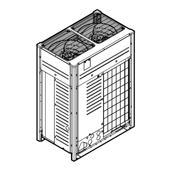
12 About the units and options Accessory pipes Øa [mm] Øb [mm] About the units and options Liquid pipe ▪ Front connection 12.1 About the outdoor unit ID Øb This installation manual concerns the VRV 5, full inverter driven, 12.7 ID Øa heat pump system. -
Page 19: 13 Special Requirements For R32 Units
13 Special requirements for R32 units Indoor unit installation Special requirements for R32 NOTICE units If one or more rooms are connected to the unit using a duct system, make sure air inlet AND outlet are connected In this chapter directly to the same room by ducting. - Page 20 Special requirements for R32 units Examples NOT OK Case Remote controller is not R32 safety system compatible Indoor units without remote controller are not allowed In case of one R32 safety system compatible remote controller, it should be the master and in the same room of the indoor unit.
-
Page 21: To Determine The Required Safety Measures
Special requirements for R32 units 13.3 To determine the required safety measures Step 1 – Determine the total amount of refrigerant in the system. Use the values on the unit nameplate to determine the total amount OTHER FLOORS of refrigerant in the system. Contains fluorinated greenhouse gases GWP: xxx GWP ×... -
Page 22: Overview: Flowchart
Special requirements for R32 units 13.3.1 Overview: flowchart Procedure to check required countermeasure for indoor unit Determine total amount of See Step 1 in above text refrigerant in the system. Total charge amount [kg] Determine the smallest area out of: - the room where an indoor unit is installed, - each of the rooms served by a ducted indoor unit installed in a different room... -
Page 23: Natural Ventilation
Special requirements for R32 units and how to set up, please check the note below or refer to the Note: Some centralised controllers can also be used as supervisor installation and operation manual delivered with the remote remote controller. For further details on installation, please refer to controller. -
Page 24: Shut-Off Valves
Special requirements for R32 units Step 3 – The total amount of refrigerant in the system MUST be less 2 In addition, apply the Natural ventilation safety measure: total than the refrigerant charge limit derived from the graph above. If room areas of installed room and adjacent room where natural NOT, natural ventilation safety measure is not allowed. - Page 25 Special requirements for R32 units Possible changes: Area of installed/ Maximum total indoor unit capacity class conditioned room [m²] 1 indoor unit per 2~5 indoor units per branch pipe port ▪ Increase the area of smallest room (installed & conditioned) branch pipe port 40 m after 1 branch...
-
Page 26: Overview: Flowchart
Special requirements for R32 units 13.4.5 Overview: flowchart §13.4.1 §13.4.2 §13.4.3 §13.4.4 No safety measure Alarm Natural ventilation Shut-off valves Select the SV unit. Make field settings in the indoor unit Determine total room area (= total area of the accordingly. -
Page 27: Combinations Of Safety Measures
Ambient outdoor temperature Mind the spacing guidelines. See the "Technical data" chapter. If the unit has to operate for 5 days in this area with high humidity (>90%), Daikin recommends to install the INFORMATION optional heater tape kit (EKBPH012TA or EKBPH020TA) Equipment meets the requirement for commercial and to keep the drain holes free. -
Page 28: Opening The Unit
14 Unit installation Power supply terminal block 14.2 Opening the unit Sealing material Moisture and dirt could enter NOT allowed 14.2.1 To open the outdoor unit Allowed DANGER: RISK OF ELECTROCUTION 14.3 Mounting the outdoor unit DANGER: RISK OF BURNING/SCALDING 14.3.1 To provide the installation structure 5~12 HP... -
Page 29: To Install The Outdoor Unit
15 Piping installation Depending on the applicable legislation and the maximum NOTICE working pressure of the unit (see "PS High" on the unit name ▪ Prepare a water drainage channel around the plate), larger piping thickness might be required. foundation to drain waste water from around the unit. During heating operation and when the outdoor 15.1.3 To select the piping size... -
Page 30: To Select Refrigerant Branch Kits
15 Piping installation 15.1.4 To select refrigerant branch kits Indoor unit capacity Piping outer diameter [mm] index Gas pipe Liquid pipe Refrigerant refnets 290≤x<392 22.2 12.7 size" [ 4 29]. For piping example, refer to "15.1.3 To select the piping 392≤x<620 28.6 ▪... -
Page 31: Installation Limitations
15 Piping installation 15.1.5 Installation limitations 15.1.6 Multiple outdoor units: Possible layouts The illustration and table below show the installation limitations. ▪ The piping between the outdoor units must be routed level or slightly upward to avoid the risk of oil retention into the piping. Pattern 1 Pattern 2 To indoor unit... -
Page 32: Connecting The Refrigerant Piping
15 Piping installation Then NOTICE >2 m >2 m Reinstall dust cap to prevent aging of O-ring and risk of leakage. To close the stop valve 1 Remove the stop valve cover. ≤2 m 2 Insert a hexagon wrench into the stop valve and turn the stop valve clockwise. -
Page 33: To Protect Against Contamination
15 Piping installation Large knockout hole Drill Points for drilling NOTICE WARNING Precautions when making knockout holes: ▪ Avoid damaging the casing. ▪ After making the knockout holes, we recommend you remove the burrs and paint the edges and areas around the edges using repair paint to prevent rusting. -
Page 34: To Connect The Refrigerant Branching Kit
15 Piping installation ▪ Make sure that the total length of the piping connected to the joint NOTICE is absolute straight for more than 500 mm. Only if a straight field Leak test and vacuum drying of field piping, SV units and piping of more than 120 mm is connected, more than 500 mm of indoor units is impossible when field expansion valves are straight section can be ensured. -
Page 35: Checking Refrigerant Piping: Setup
15 Piping installation 15.3.3 Checking refrigerant piping: Setup NOTICE ALWAYS use a recommended bubble test solution from p < p > your wholesaler. NEVER use soap water: ▪ Soap water may cause cracking of components, such as flare nuts or stop valve caps. ▪... -
Page 36: To Check For Leaks After Charging Refrigerant
16 Charging refrigerant Inside the outdoor unit NOTICE To insulate the refrigerant piping, proceed as follows: If the power of some units is turned off, the charging procedure cannot be finished properly. NOTICE In case of a multiple outdoor system, turn on the power of all outdoor units. -
Page 37: About Charging Refrigerant
16 Charging refrigerant ▪ Parameter A: If the total indoor unit capacity connection ratio 16.2 About charging refrigerant (CR)>100%, charge an additional 0.5 kg of refrigerant per outdoor unit. Once vacuum drying and leak test are finished, additional refrigerant charging can start. ▪... -
Page 38: To Charge Refrigerant: Flow Chart
16 Charging refrigerant 16.4 To charge refrigerant: Flow chart refrigerant" [ 4 38]. For more information, see "16.5 To charge Step 1 p < p > Calculate additional refrigerant charge amount: R (kg) Step 2+3 • Close valve A • Open valve B to the liquid line •... -
Page 39: Error Codes When Charging Refrigerant
16 Charging refrigerant p < p > 6 Activate setting [2‑20] to start the manual additional refrigerant charge mode. For details, see "18.1.8 Mode 2: field settings" [ 4 47]. Result: The unit will start operation. 7 Open valve A and charge refrigerant until the remaining determined additional refrigerant amount is added, and then close valve A. -
Page 40: To Fix The Fluorinated Greenhouse Gases Label
17 Electrical installation 16.8 To fix the fluorinated greenhouse Electrical installation gases label CAUTION 1 Fill in the label as follows: instructions" [ 4 4] to make "2 Specific installer safety sure this installation complies with all safety regulations. Contains fluorinated greenhouse gases RXXX GWP: XXX... -
Page 41: Specifications Of Standard Wiring Components
17 Electrical installation 17.2 Specifications of standard wiring components For standard combinations Component Single outdoor units RYMA5 RXYA8 RXYA10 RXYA12 RXYA14 RXYA16 RXYA18 RXYA20 Power supply cable 15 A 16.1 A 22 A 24 A 27 A 31 A 35 A 42 A Voltage 380-415 V Phase Frequency 50 Hz Wire size 5 core cable Must comply with national wiring regulation. -
Page 42: To Route And Fix The Interconnection Wiring
17 Electrical installation 5~12 HP 14~20 HP For earth connections, use the following method: Wire type Installation method Single-core wire Stranded conductor wire twisted to "solid- like" connection a Clockwise curled wire (single-core or twisted stranded conductor wire) b Screw c Spring washer d Flat washer e Coupling washer... -
Page 43: To Finish The Interconnection Wiring
17 Electrical installation Indoor unit Tie wrap Outdoor unit/other system interconnection (F1/F2) Knockout hole has to be removed. Close the hole to avoid small animals or dirt from entering. ▪ The interconnecting wiring between the outdoor units in the same piping system must be connected to the Q1/Q2 (Out Multi) 17.8 To connect the power supply... -
Page 44: To Connect The External Outputs
17 Electrical installation Cable routing NOTICE Route the SVEO or SVS output cable as indicated below. When connecting the earth wire, align the wire with the cut 5~12 HP 14~20 HP out section of the cup washer. Incomplete earthing may cause electrical shock. -
Page 45: Configuration
18 Configuration 1" [ 4 46] ▪ "18.1.5 To use mode Configuration 2" [ 4 46] ▪ "18.1.6 To use mode DANGER: RISK OF ELECTROCUTION settings" [ 4 46] ▪ "18.1.7 Mode 1: monitoring settings" [ 4 47] ▪ "18.1.8 Mode 2: field INFORMATION It is important that all information in this chapter is read 18.1.2 Field setting components sequentially by the installer and that the system is... -
Page 46: To Access Mode 1 Or 2
18 Configuration 18.1.4 To access mode 1 or 2 What Changing and accessing Push BS1 one time to select Initialisation: default situation the setting in mode 1 mode 1. Push BS2 to select the required NOTICE setting. Turn ON the power 6 hours before operation in order to Push BS3 one time to access the have power running to the crankcase heater and to protect selected setting's value. -
Page 47: Mode 2: Field Settings
18 Configuration [1‑5] [1‑6] [2‑8] target [°C] Code Shows ... [1‑5] The current T target parameter position [2‑9] [1‑6] The current T target parameter position target temperature during heating operation. [1‑10] [2‑9] target [°C] Shows the total number of connected indoor units. 0 (default) Auto [1‑13]... -
Page 48: Indoor Unit Field Setting
18 Configuration For details about the supervisor remote controller, see "13.2 System [2‑20] Description requirements" [ 4 19] or refer to the remote controller layout Perform a SV/indoor unit connection check. installation and user reference guide. Perform a SV units and indoor units connection [2‑60] Description check where for each indoor unit is checked if... -
Page 49: Using The Leak Detection Function
Next commissioning instructions in this chapter, a general ▪ When the height difference between indoor units is commissioning checklist is also available on the Daikin ≥50/40 m, the leak detection function can not be used. Business Portal (authentication required). 18.2.2... -
Page 50: Checklist Before Commissioning
19 Commissioning 19.2 Checklist before commissioning Air inlet/outlet Check that the air inlet and outlet of the unit is NOT 1 After the installation of the unit, check the items listed below. obstructed by paper sheets, cardboard, or any other 2 Close the unit. -
Page 51: To Perform A Test Run
19 Commissioning ▪ Check for incorrect wiring (communication check with indoor Completion Description units). Abnormal Indication of malfunction code on the ▪ Check of the stop valves opening. completion 7‑segment display. ▪ Judgement of piping length. Refer to "19.5.2 Correcting after abnormal run" [ 4 51] to take completion of the test ▪... -
Page 52: 20 Hand-Over To The User
20 Hand-over to the user INFORMATION Maintenance and service During the check operation, it is not possible to stop the unit operation from a user interface. To abort the operation, NOTICE press BS3. The unit will stop after ±30 seconds. Maintenance MUST be done by an authorised installer or service agent. -
Page 53: Checklist For Yearly Maintenance Of The Outdoor Unit
22 Troubleshooting 4 After the service is finished, plug the junction connector back in. 21.3.3 Before the maintenance and service of a Otherwise the malfunction code will be displayed on the system with SV unit user interface or on the outdoor unit 7‑segment display and normal operation will NOT be performed. -
Page 54: Error Codes: Overview
22 Troubleshooting With an interval of 1 second, the display will switch between main INFORMATION code and sub code. See the service manual for: ▪ The complete list of error codes ▪ A more detailed troubleshooting guideline for each error 22.1.1 Error codes: Overview In case other error codes appear, contact your dealer. - Page 55 22 Troubleshooting Main code Sub code Cause Solution SVEO Master Slave 1 High pressure switch was activated (S1PH) – Check stop valve situation or abnormalities in main PCB (X2A) (field) piping or airflow over air cooled coil. ▪ Refrigerant overcharge ▪ Check refrigerant amount+recharge unit. ▪...
- Page 56 22 Troubleshooting Main code Sub code Cause Solution SVEO Master Slave 1 Heat exchanger deicer temperature sensor Check connection on PCB or actuator (R11T) – main PCB (X35A) Upper heat exchanger – gas - temperature Check connection on PCB or actuator. sensor (R8T) –...
- Page 57 22 Troubleshooting Main code Sub code Cause Solution SVEO Master Slave 1 Warning because there is an error on another Check if other indoor units/SV units have a unit (indoor/SV unit) malfunction and confirm if indoor unit mix is allowed. Connection malfunction over indoor units or Check if other indoor units have a malfunction type mismatch and confirm if indoor unit mix is allowed.
-
Page 58: Refrigerant Leak Detection System
23 Disposal 22.2 Refrigerant leak detection system Normal operation During normal operation, the alarm only and supervisor remote controller have no functionality. The screen of the remote controller in alarm only and supervisor mode will be off. Operation of the remote controller can be checked by pushing the button to open the installer menu. -
Page 59: 24 Technical Data
▪ A subset of the latest technical data is available on the regional a≥10 mm a≥50 mm — Daikin website (publicly accessible). b≥300 mm b≥100 mm ▪ The full set of the latest technical data is available on the Daikin c≥10 mm c≥50 mm Business Portal (authentication required). d≥500 mm d≥500 mm 24.1 Service space: Outdoor unit e≥20 mm... -
Page 60: Piping Diagram: Outdoor Unit
24 Technical data 24.2 Piping diagram: Outdoor unit Piping diagram: 5~12 HP R16T R11T S2PH R13T S1NPH S1PH R21T R15T S1NPL Y11S R12T R10T Y10S 3D138283 Stop valve (liquid) Service port Stop valve (gas) Stop valve (equalising pipe) Charge port Installation and operation manual RYMA5+RXYA8~20A7Y1B VRV 5 heat pump 4P739915-1 –... - Page 61 24 Technical data Piping diagram: 14~20 HP R11T S2PH R13T S1NPH S1PH R21T R15T S1NPL Y11S R12T R10T 3D138283 Y10S Stop valve (liquid) Service port Stop valve (gas) Stop valve (equalising pipe) Charge port RYMA5+RXYA8~20A7Y1B Installation and operation manual VRV 5 heat pump 4P739915-1 –...
-
Page 62: Wiring Diagram: Outdoor Unit
24 Technical data Charge port / Service port Use dry contact for micro current (10 mA or less, 15 V DC). Stop valve When using the optional adapter, refer to the installation manual of the optional adapter. Filter Symbols: Check valve Field wiring Pressure relief valve Terminal block Connector... - Page 63 Solenoid valve (heat exchanger lower) the accompanying documentation. Solenoid valve (heat exchanger upper) Field supply Equipment NOT made by Daikin that can be combined with Y8S (5~12 HP Solenoid valve (gas injection) product according...
- Page 64 4P739915-1 0000000W 4P739915-1 2023.12 Verantwortung für Energie und Umwelt...
Need help?
Do you have a question about the VRV 5 RXYA8A7Y1B and is the answer not in the manual?
Questions and answers