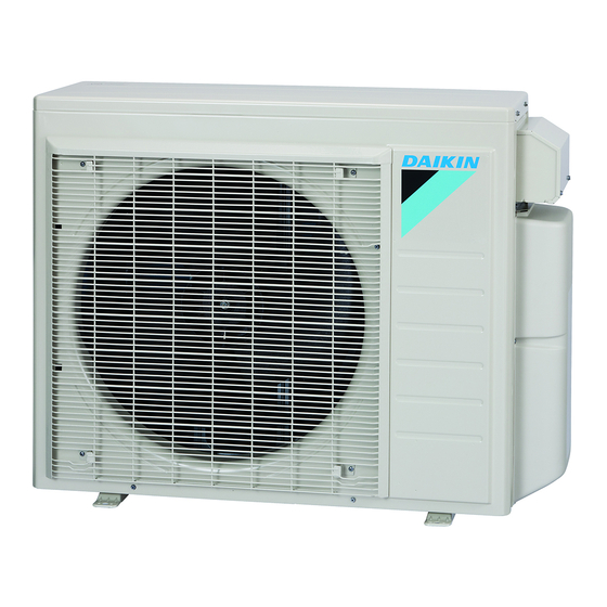
Outer Panels Si121558EC 1. Outer Panels Warning Be sure to wait for 10 minutes or more after turning off all power supplies before disassembling work. Step Procedure Points Remove the 6 screws Top panel and remove the top panel. (R22351) Remove the 8 screws of the front panel.
Page 5
Si121558EC Outer Panels Step Procedure Points Unfasten the 2 hooks When reassembling, make on the right side. sure that the 2 hooks are Front panel securely fastened. Remove the front panel. Hook (R22280) Remove the 4 screws of the discharge grille. Discharge grille (R22281) Unfasten the 2 hooks...
Outdoor Fan / Fan Motor Si121558EC 2. Outdoor Fan / Fan Motor Warning Be sure to wait for 10 minutes or more after turning off all power supplies before disassembling work. Step Procedure Points Remove the drip proof Drip proof cover cover.
Page 7
Si121558EC Outdoor Fan / Fan Motor Step Procedure Points Remove the nut and Nut size: M8 remove the outdoor fan. D-cut 13 mm (0.51 inch) (R18965) When reassembling, align mark of the fan rotor with the D-cut section of the motor shaft.
Right Side Panel / Electrical Box Si121558EC 3. Right Side Panel / Electrical Box Warning Be sure to wait for 10 minutes or more after turning off all power supplies before disassembling work. Step Procedure Points 1. Remove the terminal ...
Page 9
Si121558EC Right Side Panel / Electrical Box Step Procedure Points Remove the 19 screws Terminal board on the 5 terminal boards and disconnect the 4 connecting wires (Room A, B, C, D) and Room A Room B Power supply the power supply wire. wire power supply Connecting wire...
Page 10
Right Side Panel / Electrical Box Si121558EC Step Procedure Points 4. Remove the stop valve When reassembling, make cover and the right side sure to fit the 3 hooks. panel. Remove the 3 screws. Hook Slide the stop valve cover downward and remove it.
Page 11
Si121558EC Right Side Panel / Electrical Box Step Procedure Points Release the outdoor Some models do not have a Slit temperature thermistor Outdoor slit for outdoor temperature temperature thermistor harness. from the slit. thermistor Remove the 3 screws. When reassembling, make sure that the 2 hooks are Unfasten the 2 hooks securely fastened.
Page 12
Right Side Panel / Electrical Box Si121558EC Step Procedure Points Disconnect the [S80]: four way valve coil connector [S80] and pull out the clamp. Clamp [S80] (R22303) Disconnect the [S40]: overload protector [S40] connector [S40]. (R22304) Disconnect the relay connector for compressor.
Page 13
Si121558EC Right Side Panel / Electrical Box Step Procedure Points Pull out the clamp at the back of the electrical box. Clamp (R23007) Remove the screw and remove the electrical Electrical box. (R22308) Removal Procedure...
PCBs Si121558EC 4. PCBs Warning Be sure to wait for 10 minutes or more after turning off all power supplies before disassembling work. Step Procedure Points 1. Remove the service When reassembling, make Switch cover monitor PCB. sure that the 2 hooks are securely fastened.
Page 15
Si121558EC PCBs Step Procedure Points Unfasten the 4 Projection projections and remove the service monitor PCB. Service monitor PCB Projection (R22314) 2. Remove the main PCB. Remove the 2 screws. (R22315) Turn over the terminal Before pulling out the Terminal for power supply mounting plate.
Page 16
PCBs Si121558EC Step Procedure Points Cut the clamp and Before pulling out the Black Clamp disconnect the 2 terminals, confirm the White terminal locations. terminals for room B (black and white). Black White (R22319) (R22318) Pull out the 3 clamps. Clamp Clamp (R23008)
Page 17
Si121558EC PCBs Step Procedure Points Disconnect the [S]: to terminal board connector [S]. (R22322) Cut the clamp. Clamp (R22323) Pull out the 4 clamps. Clamp Clamp (R22324) Removal Procedure...
Page 18
PCBs Si121558EC Step Procedure Points 10 Remove the 8 screws. (R23078) 11 Unfasten the 4 hooks and remove the main PCB. Hook (R22326) Main PCB (R22327) Removal Procedure...
Si121558EC Thermistor ASSYs 5. Thermistor ASSYs Warning Be sure to wait for 10 minutes or more after turning off all power supplies before disassembling work. Step Procedure Points 1. Remove the thermistor Be careful not to lose the clip ASSY.
Page 20
Thermistor ASSYs Si121558EC Step Procedure Points 2. Remove the gas pipe The number of the gas pipe thermistors ASSY. thermistors varies depending on the model. Cut the 4 clamps and pull out the 4 gas pipe Be careful not to lose the clip thermistors.
Si121558EC Electronic Expansion Valve Coil ASSY 6. Electronic Expansion Valve Coil ASSY Warning Be sure to wait for 10 minutes or more after turning off all power supplies before disassembling work. Be careful not to get yourself burnt with the pipes and other parts that are heated by the gas brazing machine.
Partition Plate / Sound Blankets Si121558EC 7. Partition Plate / Sound Blankets Warning Be sure to wait for 10 minutes or more after turning off all power supplies before disassembling work. Step Procedure Points 1. Remove the partition When reassembling, fit the plate.
Page 23
Si121558EC Partition Plate / Sound Blankets Step Procedure Points Remove the sound Since the piping ports are blanket (outer). torn easily, remove the sound blanket carefully. Sound blanket (outer) (R22344) Remove the sound Some models do not have blanket (inner top).
Four Way Valve Si121558EC 8. Four Way Valve Warning Be sure to wait for 10 minutes or more after turning off all power supplies before disassembling work. Be careful not to get yourself burnt with the pipes and other parts that are heated by the gas brazing machine.
Page 25
Si121558EC Four Way Valve Step Procedure Points Remove the terminal cover. Terminal cover (R22348) Remove the protection Overload Protection bushing U (red) bushing. protector Disconnect the compressor lead wires and the overload protector. V (yellow) W (blue) (R20954) Heat up the 4 brazed Four way valve Brazed part parts and remove the...
Compressor Si121558EC 9. Compressor Warning Be sure to wait for 10 minutes or more after turning off all power supplies before disassembling work. Be careful not to get yourself burnt with the pipes and other parts that are heated by the gas brazing machine.
Page 27
Si121558EC Compressor Step Procedure Points Remove the terminal cover. Terminal cover (R22348) Remove the protection Overload Protection bushing U (red) bushing. protector Disconnect the compressor lead wires and the overload protector. V (yellow) W (blue) (R20954) Remove the putty. Brazed part of the Brazed part of the discharge side pipe suction side pipe...
Page 28
Revision History Month / Year Version Revised contents 08 / 2015 Si121558E First edition 02 / 2016 Si121558EA Model Addition: 2MXL18QMVJU, 3MXL24QMVJU 08 / 2018 Si121558EB Model Addition: 3MXS24RMVJU, 4MXS36RMVJU, 3MXL24RMVJU 09 / 2019 Si121558EC Model Addition: 3MXS18/24PMVM, 4MXS28/34PMVM...
Page 29
Improper installation can result in water or refrigerant leakage, electrical shock, fire or explosion. Use only those parts and accessories supplied or specified by Daikin. Ask a qualified installer or contractor to install those parts and accessories. Use of unauthorized parts and accessories or improper installation of parts and accessories can result in water or refrigerant leakage, electrical shock, fire or explosion.
Need help?
Do you have a question about the 2MXS18NMVJU and is the answer not in the manual?
Questions and answers