Mitsubishi Electric 800 Series Instruction Manual
Vector control terminal block
Hide thumbs
Also See for 800 Series:
- Instruction manual (727 pages) ,
- Instruction manual (function (534 pages) ,
- Manual (183 pages)
Table of Contents
Advertisement
Quick Links
Advertisement
Table of Contents

Related Manuals for Mitsubishi Electric 800 Series


Summary of Contents for Mitsubishi Electric 800 Series
- Page 1 INVERTER PRE-OPERATION INSTRUCTIONS Control terminal option INSTALLATION FR-A8TP WIRING INSTRUCTION MANUAL PARAMETER Vector control terminal block ORIENTATION CONTROL ENCODER FEEDBACK CONTROL VECTOR CONTROL ENCODER PULSE DIVIDING OUTPUT...
-
Page 2: Safety Instructions
Safety instructions Thank you for choosing this Mitsubishi Electric inverter control terminal option. This Instruction Manual provides handling information and precautions for use of the equipment. Incorrect handling might cause an unexpected fault. Before using this product, always read this Instruction Manual carefully to use this product correctly. - Page 3 Injury Prevention CAUTION The voltage applied to each terminal must be as specified in the Instruction Manual. Otherwise an explosion or damage may occur. The cables must be connected to the correct terminals. Otherwise an explosion or damage may occur. ...
- Page 4 CAUTION Usage As all parameters return to their initial values after the Parameter clear or All parameter clear is performed, the parameters must be set again as required before the operation is started. To avoid damage due to static electricity, static electricity in your body must be discharged before you touch this product. Maintenance, inspection and parts replacement ...
-
Page 5: Table Of Contents
Encoder specification / terminating resistor switch setting..................28 Encoder ..................................31 Wiring of control circuit ..............................33 3.3.1 Wiring method..................................33 3.3.2 Wire treatment ..................................35 3.3.3 Wiring of terminals related to the encoder .......................... 37 Encoder cables dedicated to Mitsubishi Electric motors ..................39... - Page 6 PARAMETER Extended parameter list ..............................42 Thermal protector input ..............................45 Encoder input selection ..............................46 Function differences between induction motors and PM motors................48 ORIENTATION CONTROL Connection diagram ..............................50 Terminals..................................52 Specifications ................................53 Parameter related to orientation control ........................54 5.4.1 Encoder orientation gear ratio setting ..........................54 ENCODER FEEDBACK CONTROL Connection diagram ..............................56 Specifications ................................57...
- Page 7 Appendix 1 Restricted Use of Hazardous Substances in Electronic and Electrical Products ........69 Appendix 2 Regarding Directive on Waste Electrical and Electronic Equipment ............70 REVISIONS...
-
Page 8: Pre-Operation Instructions
PRE-OPERATION INSTRUCTIONS Unpacking and product confirmation Take the control terminal option out of the package, check the product name, and confirm that the product is as you ordered and intact. The product is a control terminal option made for the FR-A800 series. 1.1.1 Product confirmation Check the enclosed items. -
Page 9: Serial Number Check
1.1.2 SERIAL number check The FR-A8TP can be used for the inverter models listed below with the following SERIAL number or later. Check the SERIAL number indicated on the inverter rating plate or package. For the location of the rating plate, refer to the Instruction Manual (Detailed) of the inverter. -
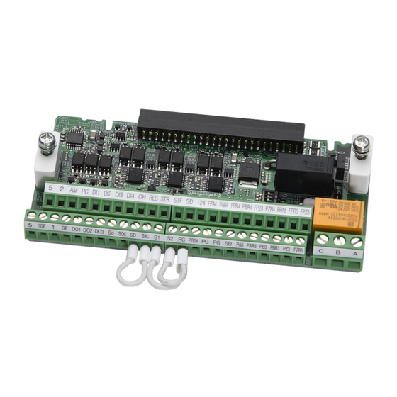
Page 10: Component Names
1.1.3 Component names SW5A Refer Symbol Name Description to page Mounting screw Fixes the option to the inverter. Terminal block Connect signal cables. Connector Connects to the control circuit connection connector of the inverter. Control logic switchover jumper connector Switches the control logic (sink logic/source logic). External thermal relay switch (SW5A) Switches the control logic of terminal OH (sink logic/source logic). -
Page 11: Terminal Layout
1.1.4 Terminal layout PRE-OPERATION INSTRUCTIONS... -
Page 12: Control Logic Switchover
1.1.5 Control logic switchover Switch the control logic of input signals as necessary. To change the control logic, change the jumper connector position on the control circuit board. Connect the jumper connector to the connector pin of the desired control logic using a pair of needle-nose pliers etc. The control logic of input signals is initially set to the sink logic (SINK). -
Page 13: Terminal Oh Control Logic Switchover
1.1.6 Terminal OH control logic switchover Change the external thermal relay switch (SW5A) position to switch the terminal OH control logic (sink logic or source logic) as necessary. The control logic of input signals is initially set to the sink logic (SINK). SINK SOURCE NOTE... -
Page 14: Terminal Connection Diagrams
Terminal connection diagrams PRE-OPERATION INSTRUCTIONS... -
Page 15: Control Terminal Specification
Control terminal specification Input signal Terminal Rated Function Common Terminal name Terminal function description symbol specification Turn ON the STF signal to start Input resistance: forward rotation and turn it OFF 4.7 kΩ Forward rotation to stop. Voltage when When the STF start The function of terminal can be... - Page 16 Terminal Rated Function Common Terminal name Terminal function description symbol specification Use this signal to reset a fault output provided when a protective function is activated. Turn ON Input resistance: SD (sink the RES signal for 0.1 s or longer, then turn it 4.7 kΩ...
- Page 17 Terminal Rated Function Common Terminal name Terminal function description symbol specification Change the input specification of the terminal 2 10 VDC ±0.4 V Frequency setting using Pr.73 when connecting it to the terminal Permissible load power supply 10E. current: 10 mA When voltage is input: Input resistance: 10...
- Page 18 Terminal Rated Function Common Terminal name Terminal function description symbol specification Control terminal Differential line option / A-phase driver/ signal input Complementary terminal Control terminal option / A-phase Differential line PAR3 inverse signal driver input terminal Control terminal Differential line option / B-phase driver/ signal input...
- Page 19 Terminal Rated Function Common Terminal name Terminal function description symbol specification Input power for the encoder power supply. Connect the external power supply (5 V, 12 V, 15 V) and the encoder power cable. When the encoder output is the differential line driver type, Encoder power Encoder only 5 V can be input.
- Page 20 Output signal Terminal Type Common Terminal name Terminal function description Rated specification symbol 1 changeover contact output that indicates that an inverter's protective function has been activated Contact capacity: 230 and the outputs are stopped. Relay output Fault: discontinuity across B and C (continuity Relay A, B, C ―...
- Page 21 Terminal Type Common Terminal name Terminal function description Rated specification symbol Control terminal option / Encoder FPA4 differential A-phase output terminal Control terminal option / Encoder FPAR4 differential A-phase inverse signal output terminal Control terminal option / Encoder Outputs A-, B- and Z-phase (home position and FPB4 differential B-phase mark pulse) signals from the encoder.
- Page 22 Safety stop signal Terminal Common Terminal name Terminal function description Rated specification symbol The terminals S1 and S2 are used for the safety stop input signal for the safety relay module. The terminals S1 and S2 Safety stop input are used at the same time (dual channel).
- Page 23 Common terminal Terminal Terminal name Terminal function description Rated specification symbol Contact input common Common terminal for the contact input terminal (sink logic). (sink) Connect this terminal to the power supply common terminal of a External transistor transistor output (open collector output) device, such as a programmable common (source) controller, in the source logic to avoid malfunction by undesirable current.
- Page 24 NOTE • The parameter names for function assignment to the terminals listed below or the terminal names for I/O terminal monitor (Pr.52) are the standard control circuit terminal names of the inverter. FR-A8TP terminal I/O terminal monitor name RL terminal function selection RM terminal function selection RH terminal function selection JOG terminal function selection...
-
Page 25: Installation
INSTALLATION Pre-installation instructions Check that the inverter's input power and the control circuit power are both OFF. CAUTION • Do not mount or remove the control terminal option while the input power is ON. Doing so may damage the inverter or the control terminal option. - Page 26 Be careful not to bend the pins of the inverter's control circuit connector, install the control terminal option and fix it with the mounting screws for the control terminal option. (Tightening torque: 0.33 to 0.4 N•m) Fix with the screws NOTE •...
-
Page 27: Precautions For Removal And Reinstallation Of The Control Circuit Terminal Block
Precautions for removal and reinstallation of the control circuit terminal block The following are the precautions to remove or reinstall the control circuit terminal block. Observe the following for proper handling to avoid malfunctions or failures of the inverter. • To remove or reinstall the control circuit terminal block, keep it upright so that it is parallel with the inverter. •... - Page 28 NOTE • Do not tilt the terminal block while tightening the screws or removing it from the inverter. (Otherwise, a stress applied to the control circuit terminal block or the control circuit connector may cause damage to them.) INSTALLATION...
-
Page 29: Wiring
WIRING Encoder specification / terminating resistor switch setting Encoder specification selection switch (SW3) Selects either differential line driver or complementary. It is initially set to the complementary. Switch its position according to the output circuit. Complementary (initial status) Differential line driver WIRING... - Page 30 Terminating resistor selection switch (SW1) Selects "ON"/"OFF" of the internal terminating resistor. Set the switch to "OFF (initial status)" when an encoder output type is complementary and set to "ON" when differential line driver. ON: with internal terminating resistor OFF: without internal terminating resistor (initial status) Internal terminating resistor-OFF...
- Page 31 Motor used and switch setting Power supply Encoder specification Terminating resistor Motor selection switch (SW3) selection switch (SW1) specification Mitsubishi Electric standard motor with SF-JR Differential encoder SF-HR Differential Mitsubishi Electric high-efficiency motor with *1*3 Others encoder SF-JRCA Differential...
-
Page 32: Encoder
Encoder Position detector (pulse encoder) Output pulse specifications Differential line driver Complementary A/A signal 1000 P/R to 4096 P/R A signal 1000 P/R to 4096 P/R Position detector B/B signal 1000 P/R to 4096 P/R B signal 1000 P/R to 4096 P/R Encoder Z/Z signal 1 P/R Z signal 1 P/R... - Page 33 Power supply Prepare an encoder's power supply (5 V, 12 V, 15 V, etc.) according to the encoder to be used. When the encoder output is the differential line driver type, only 5 V can be input. Make the voltage of the external power supply same as the encoder output voltage.
-
Page 34: Wiring Of Control Circuit
Wiring of control circuit 3.3.1 Wiring method Refer to page 35 and treat the wires. Loosen the terminal screw and insert the cable into the terminal. Tighten the screw according to the specified tightening torque. Undertightening may cause cable disconnection or malfunction. Overtightening may cause a short circuit or malfunction due to damage to the screw or unit. - Page 35 NOTE • For the connection to the terminal 5, use a screwdriver with a diameter of 1.6 mm or less. Put the screwdriver to avoid contact with the mounting screw area. φ 1.6 mm or less Avoid contact with mounting screw area •...
-
Page 36: Wire Treatment
3.3.2 Wire treatment • For the control circuit wiring except for terminals related to the encoder, strip off the sheath of a cable and use as it is. • Untwist the shielded twisted pair cables after stripping its sheath. Also, treat the shielding wires of the shielded twisted pair cable to ensure that they will not contact conductive areas. - Page 37 NOTE Crimp terminals commercially available (as of October 2020. The product may be changed without notice.) • Phoenix Contact Co., Ltd. Ferrule part No. Wire gauge Crimping tool Terminal screw size With insulation Without model No. sleeve insulation sleeve M3 (Terminals A, B, C) 0.75 AI 0,75-6GY A 0,75-6...
-
Page 38: Wiring Of Terminals Related To The Encoder
3.3.3 Wiring of terminals related to the encoder Use shielded twisted pair cables (0.2 mm or larger) for connection the encoder. For the wiring to the terminals PG and SD, use several cables in parallel or use a thick cable, according to the wiring length. To protect the cables from noise, run them away from any source of noise (e.g. - Page 39 To reduce noise of the encoder cable, earth (ground) the encoder's shielded cable to the enclosure (as close as possible to the inverter) with a metal P-clip or U-clip. Earthing (grounding) example using a P-clip Encoder cable Shield P-clip NOTE •...
-
Page 40: Encoder Cables Dedicated To Mitsubishi Electric Motors
Encoder cables dedicated to Mitsubishi Electric motors Use dedicated encoder cables to connect with Mitsubishi Electric encoder-equipped motors. FR-V7CBL For SF-PR-SC, SF-V5RU and SF-THY • A P-clip for earthing (grounding) a shielded cable is provided. FR-A800 F-DPEVSB 12P 0.2 mm... - Page 41 FR-JCBL For SF-JR/HR/JRCA/HRCA (with encoder) FR-A800 F-DPEVSB 12P 0.2 mm D/MS3057-12A Encoder (FR-A8TP) Approx. 140 mm PAR3 Earth cable PBR3 Positioning keyway PZR3 60mm D/MS3106B20-29S D/MS3106B20-29S (As viewed from wiring side) 2 mm 5 VDC power supply Type Length L (m) FR-JCBL5 FR-JCBL15 FR-JCBL30...
- Page 42 Connection terminal compatibility table Motor SF-PR-SC, SF-V5RU, SF-THY SF-JR/HR/JRCA/HRCA (with encoder) Encoder cable FR-V7CBL FR-JCBL PAR3 Keep this open. PBR3 Keep this open. FR-A8TP terminal PZR3 Keep this open. WIRING...
-
Page 43: Parameter
PARAMETER Extended parameter list When the FR-A8TP is installed in the inverter, the following parameters are extended. Minimum Initial Refer to Name Setting range setting group value page increments A510 Stop position command selection 0, 1, 9999 9999 A526 Orientation speed 0 to 30 Hz 0.01 Hz 2 Hz... - Page 44 Minimum Initial Refer to Name Setting range setting group value page increments G241 Feedback gain 0 to 100 A525 Orientation selection 0 to 2, 10 to 12 A540 Number of machine side gear teeth 0 to 32767 A541 Number of motor side gear teeth 0 to 32767 A542 Orientation speed gain (P term)
- Page 45 Minimum Initial Refer to Name Setting range setting group value page increments Control terminal option—Encoder position C243 0, 1 tuning setting/status H415 Speed limit 0 to 400 Hz 0.01 Hz 20 Hz H022 Thermal protector input 0, 1 Control terminal option—Encoder magnetic C244 0 to 16383, 65535 65535...
-
Page 46: Thermal Protector Input
Thermal protector input Initial Setting Name Description group value range Terminal OH is invalid. H022 Thermal protector input Terminal OH is valid. • When the motor with a temperature detector for overheat protection is used, use terminal OH to input contact signals of the thermal relay, etc. -
Page 47: Encoder Input Selection
Encoder input selection Initial Setting Name Description group value range Control terminal option- Set the number of pulses output from the encoder connected to the C240 Number of encoder 2048 0 to 4096 FR-A8TP. pulses Set the number of pulses before it is multiplied by 4. Set when using a motor (encoder) for Set for the operation at 120 which forward rotation is clockwise... - Page 48 • Using the FR-A8TP together with the Vector control compatible plug-in option enables Vector control or machine end orientation control by switching between two encoder-equipped motors. Use Pr.862 to set the combination of the motors (first/second) and the options (FR-A8TP / Vector control compatible plug-in option). RT=ON Pr.862 Pr.393...
-
Page 49: Function Differences Between Induction Motors And Pm Motors
Function differences between induction motors and PM motors • This section describes function differences between induction motors and PM motors. Control method Induction Control method PM motor motor V/F control ○ — Advanced magnetic flux vector control ○ — Vector control ○... - Page 50 Function Induction motor PM motor Brake sequence function ○ ○ Offline auto tuning ○ (Sensorless) ○ Forward rotation signal (Y30) / Reverse rotation signal (Y31) / ○ ○ Regenerative status signal (Y32) Deceleration check ○ ○ Speed limit ○ — X18 signal switchover ○...
-
Page 51: Orientation Control
ORIENTATION CONTROL The inverter can adjust the stop position (Orientation control) using a position detector (encoder) attached to a place such as the main shaft of the machine. For the details of the parameters used for orientation control, refer to the Instruction Manual (Detailed) of the inverter. Connection diagram For 24 V complementary type (SF-V5RU) SF-JR motor with encoder... - Page 52 The power supply of the fan for a 7.5 kW or lower dedicated motor is single phase. (200 V/50 Hz, 200 to 230 V/60 Hz) The pin number differs according to the encoder used. Use Pr.178 to Pr.182, Pr.185, or Pr.189 (input terminal function selection) to assign the function to a terminal. For the details, refer to the Instruction Manual (Detailed) of the inverter.
-
Page 53: Terminals
Terminals Option FR-A8AX terminal Terminal symbol Terminal name Description Input the digital signal at the relay contact or open collector terminal. X0 to X15 Digital signal input terminal Using Pr.360, speed or position command is selected as the command signal entered. Use this terminal when a digital signal read timing signal is necessary. -
Page 54: Specifications
Specifications Item Description ±1.5° Repeated positioning Depends on the load torque, moment of inertia of the load, orientation, creep speed, or position loop switching accuracy position, etc. Encoder-mounted shaft speed (6000 r/min with 1024 pulse encoder) Permissible speed The drive shaft and encoder-mounted shaft must be coupled directly or via a belt without any slip. Gear changing shafts cannot be applied. -
Page 55: Parameter Related To Orientation Control
Parameter related to orientation control 5.4.1 Encoder orientation gear ratio setting Set the encoder orientation gear ratio for machine end orientation control. To perform machine end orientation control, the FR-A8TP and the plug-in option FR-A8AP must be installed. Set "1" in Pr.862 Encoder option selection. Connect the motor-end encoder to the FR-A8TP, and connect the machine-end encoder to the FR-A8AP. - Page 56 NOTE • Pulley ratio ..Ratio of vector-driven motor side pulley diameter to spindle side pulley diameter Spindle side Motor side Setting example (When the numbers of gear teeth are as follows) A:15, C: 43, E: 60, B: 10, D: 28, F:55 Pr.394 = 15 ...
-
Page 57: Encoder Feedback Control
ENCODER FEEDBACK CONTROL Mount FR-A8TP to an FR-A800 series inverter to perform encoder feedback control under V/F control or Advanced magnetic flux vector control. This controls the inverter output frequency so that the motor speed is constant to the load variation by detecting the motor speed with the speed detector (encoder) to feed back to the inverter. -
Page 58: Specifications
The pin number differs according to the encoder used. Connect the encoder so that there is no looseness between the motor and motor shaft. Speed ratio must be 1:1. Earth (ground) the shield of the encoder cable to the enclosure using a tool such as a P-clip. (Refer to page 37.) For the differential line driver, set the terminating resistor selection switch to the ON position. -
Page 59: Vector Control
VECTOR CONTROL When the FR-A8TP is mounted on the FR-A800 series, full-scale vector control operation can be performed using a motor with encoder. (For the details, refer to the Instruction Manual (Detailed) of the inverter.) Speed control, torque control, and position control are enabled under Vector control for induction motors. Speed control and position control are enabled under Vector control for PM motors. -
Page 60: Connection Diagram
Connection diagram Speed control Vector control dedicated motor (SF-PR-SC, SF-V5RU, SF-THY), Standard motor with encoder (SF-JR), 24 V complementary 5 V differential line driver SF-PR-SC, SF-JR motor with encoder Inverter MCCB SF-V5RU, SF-THY Three-phase AC power supply Earth (Ground) MCCB Inverter PAR3... - Page 61 Torque control (available with induction motors only) Vector control dedicated motor (SF-PR-SC, SF-V5RU, SF-THY), 24 V Standard motor with encoder (SF-JR), complementary 5 V differential line driver SF-PR-SC, SF-JR motor with encoder Inverter MCCB SF-V5RU, SF-THY Three-phase AC power supply Earth (Ground)
- Page 62 Position control Vector control dedicated motor (SF-PR-SC, SF-V5RU, SF-THY), 24 V complementary SF-PR-SC, MCCB SF-V5RU, SF-THY Three-phase AC power supply Positioning unit MELSEC-Q QD75P[ ]N/QD75P[ ] MCCB MELSEC-L LD75P[ ] R/L1 Three-phase Inverter AC power S/L2 supply T/L3 Earth Thermal (ground) relay...
- Page 63 The pin number differs according to the encoder used. Speed, control, torque control, and position control by pulse train input are available with or without the Z-phase being connected. Connect the encoder so that there is no looseness between the motor and motor shaft. Speed ratio must be 1:1. Earth (ground) the shield of the encoder cable to the enclosure using a tool such as a P-clip.
-
Page 64: Setting Procedure Of Vector Control For Motor With Encoder
Setting procedure of Vector control for motor with encoder Follow the following procedure to change the setting for the Vector control for the motor with encoder. (For the details, refer to the Instruction Manual (Detailed) of the inverter.) Induction motor Set the applied encoder. - Page 65 PM motor Set the applied encoder. (Pr.852, Pr.851) Set Pr.852 Control terminal option-Encoder rotation direction and Pr.851 Control terminal option-Number of encoder pulses in accordance with the encoder specification. Set the applied motor. (Pr.9, Pr.71, Pr.80, Pr.81, Pr.83, Pr.84) Set Pr.71 Applied motor, Pr.9 Rated motor current, Pr.80 Motor capacity, Pr.81 Number of motor poles, Pr.83 Rated motor voltage, and Pr.84 Rated motor frequency according to the motor specifications.
-
Page 66: Specifications
Specifications Item Description Speed control range 1:1500 (both driving/regeneration Speed variation ratio ±0.01% (100% means 3000 r/min) Speed control Speed response 130 Hz Maximum speed 400 Hz (102400 pulses/s or less encoder pulses) Torque control range 1:50 Absolute torque accuracy Torque control ±10% Repeated torque accuracy... -
Page 67: Encoder Pulse Dividing Output
ENCODER PULSE DIVIDING OUTPUT Pulse input of encoder connected to the inverter is divided and output from the FR-A8TP terminal. Connection diagram Motor end Encoder A-, B-, Z-phases Inverter FR-A8TP A-phase FPA5 (A-phase) Division ratio Encoder pulse output B-phase FPB5 (B-phase) (open collector) Pr.863 setting (Z-phase) - Page 68 NOTE • For open collector output, the signal may become unstable if the input resistance of the connected device is large and the device may detect the signal incorrectly. In this case, adding a pull-up resistor as shown below will improve the phenomenon.
-
Page 69: Parameter Related To Encoder Pulse Dividing Output
Parameter related to encoder pulse dividing output Initial Setting Name Description group value range The encoder pulse signal at the motor end can be divided in Control terminal option- division ratio set in Pr.863 and output. M600 Encoder pulse division 1 to 32767 Use this parameter to make the response of the machine to be ratio... -
Page 70: Appendix
APPENDIX Appendix 1 Restricted Use of Hazardous Substances in Electronic and Electrical Products The mark of restricted use of hazardous substances in electronic and electrical products is applied to the product as follows based on the “Management Methods for the Restriction of the Use of Hazardous Substances in Electrical and Electronic Products”... - Page 71 Appendix 2 Regarding Directive on Waste Electrical and Electronic Equipment This symbol mark is for EU countries only, and is according to the directive 2012/19/ EU Article 14 Information for users and Annex IX. This symbol mark means that electrical and electronic equipment, at their end-of-life, should be disposed of separately from your household waste.
- Page 72 MEMO APPENDIX...
- Page 73 REVISIONS *The manual number is given on the bottom left of the back cover. Revision date *Manual number Revision Dec. 2014 IB(NA)-0600574ENG-A First edition Addition Dec. 2017 IB(NA)-0600574ENG-B • Precautions for removal and reinstallation of the control circuit terminal block •...
- Page 74 INVERTER HEAD OFFICE: TOKYO BUILDING 2-7-3, MARUNOUCHI, CHIYODA-KU, TOKYO 100-8310, JAPAN IB(NA)-0600574ENG-D(2308) MEE Printed in Japan Specifications subject to change without notice.
Need help?
Do you have a question about the 800 Series and is the answer not in the manual?
Questions and answers