
Related Manuals for Mitsubishi Electric FR-A872-E


Summary of Contents for Mitsubishi Electric FR-A872-E
- Page 1 INVERTER A800-E FR-A872-E (SEPARATED CONVERTER TYPE) INSTRUCTION MANUAL (HARDWARE) High functionality and high performance FR-A872-05690 to 07150-E...
-
Page 2: Table Of Contents
Safety instructions..............4 Chapter 1 INTRODUCTION . - Page 3 2.10 Installing a communication option ..........67 Chapter 3 PRECAUTIONS FOR USE OF THE INVERTER .
- Page 4 5.2.6 Measurement of inverter output frequency ............104 5.2.7 Insulation resistance test using megger .
-
Page 5: Safety Instructions
• A person who possesses a certification in regard with electric appliance handling, or person took a proper engineering training. Such training may be available at your local Mitsubishi Electric office. Contact your local sales office for schedules and locations. - Page 6 Electric shock prevention WARNING Do not remove the front cover or the wiring cover while the power of this product is ON, and do not run this product with the front cover or the wiring cover removed as the exposed high voltage terminals or the charging part of the circuitry can be touched.
- Page 7 Additional instructions The following instructions must be also followed. If this product is handled incorrectly, it may cause unexpected fault, an injury, or an electric shock. CAUTION Transportation and installation To prevent injury, wear cut-resistant gloves when opening packaging with sharp tools. ...
- Page 8 WARNING Usage Stay away from the equipment after using the retry function in this product as the equipment will restart suddenly after the output shutoff of this product. Depending on the function settings of this product, the product does not stop its output even when the STOP/RESET key on the operation panel is pressed.
- Page 9 CAUTION Usage The electronic thermal O/L relay function may not be enough for protection of a motor from overheating. It is recommended to install an external thermal relay or a PTC thermistor for overheat protection. Do not repeatedly start or stop this product with a magnetic contactor on its input side. Doing so may shorten the life of this product.
- Page 10 Application of caution labels Caution labels are used to ensure safety during use of Mitsubishi Electric inverters. Apply the following labels to the inverter if the "retry function" and/or "automatic restart after instantaneous power failure" have been enabled. For the retry function...
- Page 11 MEMO...
-
Page 12: Chapter 1 Introduction
CHAPTER 1 INTRODUCTION Product checking and accessories .........................13 Inverter component names .............................14 About the related manuals............................15... - Page 13 Parameter unit Parameter unit (FR-PU07) Operation panel and parameter unit Inverter Mitsubishi Electric FR-A800 series inverter (separated converter type) Ethernet board Ethernet communication board (FR-A8ETH) Vector control compatible option FR-A8AP/FR-A8AL/FR-A8APA/FR-A8APR/FR-A8APS (plug-in option), FR-A8TP (control terminal option) Parameter number (Number assigned to function)
-
Page 14: Product Checking And Accessories
Product checking and accessories Unpack the product and check the rating plate and the capacity plate of the inverter to ensure that the model is as ordered and the product is intact. Inverter model Symbol Voltage class Symbol Structure, functionality Symbol Description Communication... -
Page 15: Inverter Component Names
Inverter component names Component names are as follows. 1. INTRODUCTION 1.2 Inverter component names... -
Page 16: About The Related Manuals
Symbol Name Description Refer to page Plug-in option connector 1 Instruction Connects a plug-in option or a communication option. Manual of the Plug-in option connector 3 option The connector 2 cannot be used because the Ethernet board is installed in the Plug-in option connector 2 initial status. - Page 17 MEMO 1. INTRODUCTION 1.3 About the related manuals...
- Page 18 CHAPTER 2 INSTALLATION AND WIRING Peripheral devices ..............................18 Removal and reinstallation of the operation panel or the front covers..............21 Installation of the inverter and enclosure design ....................24 Terminal connection diagrams..........................30 Main circuit terminals ..............................35 Control circuit................................41 Communication connectors and terminals......................57 Connection to a motor with encoder (Vector control) .....................60 Parameter settings for a motor with encoder......................66 2.10...
-
Page 19: Chapter 2 Installation And Wiring
INSTALLATION AND WIRING This chapter explains the installation and the wiring of this product. Always read the instructions before use. Peripheral devices 2.1.1 Inverter and peripheral devices (c) Three-phase AC power supply (b) Converter unit (a) Inverter (g) USB connector (FR-CC2) (FR-A802) USB host... -
Page 20: Peripheral Devices
Refer to Symbol Name Overview page Inverter (FR-A802) The life of the inverter and the converter unit is influenced by the surrounding air temperature. The surrounding air temperature should be as low as possible within the permissible range. This must be noted especially when the inverter is 24, 30, installed in an enclosure. - Page 21 Refer to the following table to prepare appropriate peripheral devices. *1*3 Motor output Applicable converter Magnetic contactor (MC) *1*2 MCCB or Earth Leakage Circuit Breaker (ELB) (kW) model converter unit's input side FR-CC2-N450K 700 A 660 A FR-CC2-N500K 800 A 660 A FR-CC2-N560K 800 A...
-
Page 22: Removal And Reinstallation Of The Operation Panel Or The Front Covers
Removal and reinstallation of the operation panel or the front covers Removal and reinstallation of the operation panel • Loosen the two screws on the operation panel. • Press the upper edge of the operation panel while pulling (These screws cannot be removed.) out the operation panel. - Page 23 Removal of the lower main circuit terminal cover (a) Remove the mounting screws to remove the lower main circuit terminal cover. (b) With the cover removed, terminals U, V, and W can be wired and the cooling fan can be replaced (refer to page 98).
- Page 24 Loosen Loosen Loosen (c) With the lower cover removed, loosen the mounting screws on the upper cover. (These screws cannot be removed.) (d) Pull out the upper cover using its upper side as a support. (e) With the upper cover removed, the control circuit can be wired and the plug-in option can be installed. ...
-
Page 25: Installation Of The Inverter And Enclosure Design
Installation of the inverter and enclosure design When designing or manufacturing an inverter enclosure, determine the structure, size, and device layout of the enclosure by fully considering the conditions such as heat generation of the contained devices and the operating environment. An inverter uses many semiconductor devices. - Page 26 Humidity Normally operate the inverter within the ambient air humidity of 45% to 95%. Too high humidity will pose problems of reduced insulation and metal corrosion. On the other hand, too low humidity may cause a spatial electrical breakdown. The humidity conditions for the insulation distance defined in JEM 1103 standard "Insulation Distance from Control Equipment"...
-
Page 27: Amount Of Heat Generated By The Inverter
Especially when impacts are applied repeatedly, caution must be taken because such impacts may break the installation feet. Countermeasure • Provide the enclosure with rubber vibration isolators. • Strengthen the structure to prevent the enclosure from resonance. • Install the enclosure away from the sources of the vibration. 2.3.2 Amount of heat generated by the inverter When the heat sink is installed inside the enclosure, the amount of heat generated by the inverter unit and converter unit is... - Page 28 Cooling system Enclosure structure Comment This system is low in cost and generally used, but the Natural ventilation (enclosed enclosure size increases as the inverter capacity type / open type) increases. This system is for relatively small capacities. Natural Being a totally enclosed type, this system is the most Natural ventilation (totally appropriate for hostile environment having dust, dirt, oil enclosed type)
-
Page 29: Inverter Installation
2.3.4 Inverter installation Inverter placement • Install the inverter on a strong surface securely with screws. • Leave enough clearances and take cooling measures. • Avoid places where the inverter is subjected to direct sunlight, high temperature and high humidity. •... - Page 30 Side-by-side installation (0 cm clearance) is available. Note that clearance to pass cables is required. (Refer to page 50.) A 10 cm or more clearance is required below the bottom of the enclosure (regardless of the installation feet). There needs to be a space of at least 60 cm in front of the inverter to replace the cooling fan. Refer to page 97 for fan replacement.
-
Page 31: Terminal Connection Diagrams
Terminal connection diagrams FM type Sink logic Main circuit terminal Control circuit terminal Inverter Converter unit Fuse R/L1 Motor S/L2 T/L3 Jumper Earth (Ground) R1/L11 ∗1 S1/L21 Earth Main circuit (Ground) Control circuit Control input signals Relay output ∗7 (No voltage input allowed) ∗2 Forward rotation start Relay output 1... - Page 32 A jumper is installed across terminal R1/L11 and terminal P/+, and across terminal S1/L21 and terminal N/-. When using a separate power supply for the control circuit, remove the jumpers connected to terminals R1/L11 and S1/L21. The function of these terminals can be changed using the Input terminal function selection (Pr.178 to Pr.189). Terminal JOG is also used as a pulse train input terminal.
- Page 33 CA type Source logic Main circuit terminal Control circuit terminal Inverter Converter unit Fuse R/L1 Motor S/L2 T/L3 Jumper Earth (Ground) R1/L11 ∗1 S1/L21 Earth Main circuit (Ground) Control circuit Control input signals Relay output ∗7 (No voltage input allowed) ∗2 Forward rotation start Relay output 1 Reverse rotation start...
- Page 34 The X10 signal (NC contact input specification) is assigned to the terminal MRS in the initial setting. Set Pr.599 = "0" to change the input specification of the X10 signal to NO contact. Terminal input specifications can be changed by analog input specification switchover (Pr.73, Pr.267). To input voltage (0 to 5 V/0 to 10 V), set the voltage/current input switch OFF.
- Page 35 Connection between the converter unit and the inverter Wire correctly to ensure the command transmission from the converter unit to the inverter. Otherwise, the converter unit and the inverter may be damaged. For the wiring length, refer to the following tables. Location in the connection diagram Total wiring length Between the terminals P and P and 50m or shorter...
-
Page 36: Main Circuit Terminals
Main circuit terminals 2.5.1 Details on the main circuit terminals of the inverter Refer to Terminal symbol Terminal name Terminal function description page U, V, W Inverter output Connect a three-phase squirrel-cage motor. — Connected to terminals P/+ and N/-. To retain the fault display and fault output, or to use the converter unit (FR-CC2), remove the jumpers Power supply for the control installed in terminals R1/L11 and S1/L21, and apply external power... -
Page 37: Terminal Layout Of The Main Circuit Terminals, Wiring Of Power Supply And The Motor
2.5.3 Terminal layout of the main circuit terminals, wiring of power supply and the motor Terminal layout Converter unit Inverter To converter To inverter unit Charge lamp Charge lamp Jumper Jumper R/L1 S/L2 T/L3 Power supply Motor NOTE • Make sure the power cables are connected to the R/L1, S/L2, and T/L3. (Phase need not be matched.) Never connect the power cable to the U, V, and W of the inverter. - Page 38 Recommended bus bar dimensions (for terminals P/+ and N/-) Refer to the following for bus bars for terminals P/+ and N/-. 2×R7.5 φ15 5×45° (30) (Unit : mm) The bus bar dimensions differ depending on the arrangement of the inverter and the converter unit as shown in the following table. Arrangement of the units Dimension Left...
-
Page 39: Applicable Cables And Wiring Length
• The figure below shows how to connect bus bars to the main circuit terminals. NOTE • Ensure the upper main circuit terminal cover (front) and the lower main circuit terminal cover is reinstalled before the operation is started. 2.5.4 Applicable cables and wiring length Select a recommended size cable to ensure that the voltage drop ratio is within 2%. - Page 40 • Converter unit (FR-CC2) Bus bar dimensions (for each Terminal Earth (ground) cable size Converter model Tightening phase) screw FR-CC2-N[] torque (N·m) size R, S, T PVC cables, etc. (mm 450K to 630K M12 (M10) 24.5 6 mm thick and 40 mm wide 2×80 •...
-
Page 41: Earthing (Grounding) Precautions
2.5.5 Earthing (grounding) precautions • Always earth (ground) the motor, the inverter, and the converter unit. Purpose of earthing (grounding) Generally, an electrical apparatus has an earth (ground) terminal, which must be connected to the ground before use. An electrical circuit is usually insulated by an insulating material and encased. However, it is impossible to manufacture an insulating material that can shut off a leakage current completely, and actually, a slight current flows into the case. -
Page 42: Control Circuit
Control circuit 2.6.1 Details on the control circuit terminals of the inverter For the parameter details, refer to the Instruction Manual (Function). Input signal Terminal Type Terminal name Terminal function description Rated specification symbol Turn ON the STF signal to start forward rotation When the STF and STR Forward rotation start and turn it OFF to stop. - Page 43 Terminal Type Terminal name Terminal function description Rated specification symbol 10 ±0.4 VDC, permissible load When connecting the frequency setting potentiometer at an initial status, current: 10 mA Frequency setting connect it to terminal 10. power supply Change the input specifications of terminal 2 using Pr.73 when 5 ±0.5 VDC, connecting it to terminal 10E.
- Page 44 Output signal Terminal Type Terminal name Terminal function description Rated specification symbol 1 changeover contact output that indicates that an inverter's protective Relay output 1 (fault function has been activated and the outputs are stopped. Contact capacity: 230 output) Fault: discontinuity across B and C (continuity across A and C), Normal: VAC 0.3 A continuity across B and C (discontinuity across A and C)
-
Page 45: Details On The Control Circuit Terminals Of The Converter Unit (Fr-Cc2)
Communication Terminal Type Terminal name Terminal function description symbol Communication can be made via Ethernet. Category: 100BASE-TX/10BASE-T Data transmission speed: 100 Mbps (100BASE-TX) / 10 Mbps (10BASE-T) Transmission method: Baseband — Ethernet connector Maximum segment length: 100 m between the hub and the inverter Number of cascade connection stages: Up to 2 (100BASE-TX) / up to 4 (10BASE-T) Interface: RJ-45 Number of interfaces available: 1... - Page 46 Input signal Terminal Type Terminal name Terminal function description Rated specification symbol Use this signal to reset a fault output provided when a protective function is activated. Turn ON the RES signal for 0.1 second or longer, then turn it OFF.
-
Page 47: Control Logic (Sink/Source) Change
CAUTION • Do not use the empty terminals (NC) of the control circuit. Doing so may lead to damage of the converter unit and the inverter. • Always connect the terminal RDA of the converter unit and the terminal MRS (X10) of the inverter, and the terminal SE of the converter unit and the terminal SD (terminal PC in the source logic) of the inverter. - Page 48 • In the source logic, a signal turns ON when a current enters into the corresponding signal input terminal. Terminal PC is common to the contact input signals. Terminal SE is common to the open collector output signals. Current flow concerning the input/output signal Current flow concerning the input/output signal when sink logic is selected when source logic is selected...
-
Page 49: Wiring Of Inverter Control Circuit
2.6.4 Wiring of inverter control circuit Control circuit terminal layout 1 F/C +24 SD So SOC S1 S2 PC 5 10E 10 SE SE IPF OL FU PC RL RM RH RT AU STP MRS SD SD STF STR JOG (X10)*2 This terminal operates as terminal FM for the type FM inverter. - Page 50 • NICHIFU Co., Ltd. Blade terminal Insulation cap product Crimping tool product Cable gauge (mm product number number number 0.3 to 0.75 BT 0.75-11 VC 0.75 NH 69 Insert the wires into a socket. When using single wire or stranded wire without crimp terminal, push an open/close button all the way down with a flathead screw driver, and insert the wire.
-
Page 51: Wiring Precautions
• In the source logic, terminal PC is a common terminal for the contact input terminals (STF, STR, STP (STOP), RH, RM, RL, JOG, RT, MRS, RES, AU, CS). The open collector circuit is isolated from the internal control circuit by photocoupler. •... -
Page 52: When Using Separate Power Supplies For The Control Circuit And The Main Circuit
• Separate the wiring of the control circuit away from the wiring of the main circuit (except for terminals R1/L11 and S1/L21). Make cuts in rubber bush of the inverter side and lead the wires through. <Wiring example> Rubber bush (viewed from inside) Make cuts along the lines on the inside with a cutter knife... - Page 53 Power supply terminal block for the control circuit Power supply terminal block for the control circuit R1/L11 S1/L21 (a) Remove the upper screws. (b) Remove the lower screws. (c) Pull the jumper toward you to remove. (d) Connect the separate power supply cable for the control circuit to the upper terminals (R1/L11, S1/L21). NOTE •...
-
Page 54: When Supplying 24 V External Power To The Control Circuit
2.6.7 When supplying 24 V external power to the control circuit Connect the 24 V external power supply across terminals +24 and SD to turn the I/O terminal ON/OFF operation, keep the operation panel ON, and carry out communication during communication operation even at power-OFF state of inverter's main circuit power supply. - Page 55 Operation while the 24 V external power is supplied • Fault records and parameters can be read and parameters can be written (when the parameter write from the operation panel is enabled) using the operation panel keys. • The safety stop function is invalid during the 24 V external power supply operation. •...
-
Page 56: Safety Stop Function
2.6.8 Safety stop function Function description The terminals related to the safety stop function are as follows. Terminal Terminal function description symbol Status of both the circuit between terminals S1 and SIC and Input terminal as the safety stop channel 1. the circuit between terminals S2 and SIC Open: Safety stop is activated. - Page 57 Safety stop function operation Output Output Internal *1*2 Input terminal Operation panel indication Input *8*9*10 terminal signal safety circuit Inverter operating status power status So (SO) SAFE E.SAF — — — Output shutoff (Safe state) Not displayed Not displayed Normal Operation enabled Not displayed...
-
Page 58: Communication Connectors And Terminals
Communication connectors and terminals 2.7.1 PU connector Mounting the operation panel or the parameter unit on the enclosure surface • Having an operation panel or a parameter unit on the enclosure surface is convenient. With a connection cable, the operation panel or the parameter unit can be mounted to the enclosure surface and connected to the inverter. -
Page 59: Ethernet Connector
2.7.2 Ethernet connector Ethernet communication specifications Item Description Category 100BASE-TX/10BASE-T Data transmission speed 100 Mbps (100BASE-TX) / 10 Mbps (10BASE-T) Transmission method Baseband Maximum segment length 100 m between the hub and the inverter Number of cascade connection Up to 2 (100BASE-TX) / up to 4 (10BASE-T) stages Interface RJ-45... - Page 60 • When the inverter recognizes the USB memory device without any problem, is briefly displayed on the operation panel. • When the USB memory device is removed, is briefly displayed on the operation panel. • The operating status of the USB host can be checked on the LED display of the inverter. LED display status Operating status No USB connection.
-
Page 61: Connection To A Motor With Encoder (Vector Control)
Connection to a motor with encoder (Vector control) Using encoder-equipped motors together with a Vector control compatible option enables speed, torque, and positioning control operations under orientation control, encoder feedback control, and full-scale Vector control. This section explains wiring for use of the FR-A8AP. ... - Page 62 Switches on the FR-A8AP • Encoder type selection switch (SW3) Selects either the differential line driver or complementary setting. It is initially set to the differential line driver. Switch its position according to the output circuit. Differential line driver (initial status) Complementary •...
- Page 63 Encoder cable FR-JCBL FR-A800 F-DPEVSB 12P 0.2 mm D/MS3057-12A (FR-A8AP) Approx. 140 mm Earth cable 60 mm Positioning keyway D/MS3106B20-29S D/MS3106B20-29S (As viewed from wiring side) 2 mm Model Length L (m) FR-JCBL5 FR-JCBL15 FR-JCBL30 FR-V7CBL FR-A800 (FR-A8AP) F-DPEVSB 12P 0.2 mm D/MS3057-12A...
- Page 64 NOTE • Information on blade terminals Commercially available products (as of January 2017) Phoenix Contact Co., Ltd. Ferrule part No. Terminal screw Cable gauge Crimping tool Without insulation size name With insulation sleeve sleeve AI 0,34-6TQ A 0,34-7 CRIMPFOX 6 AI 0,5-6WH A 0,5-6 NICHIFU Co., Ltd.
- Page 65 • Torque control Standard motor with encoder, 5 V differential line driver Motor with encoder Inverter To converter unit Earth Forward rotation start FR-A8AP (Ground) Reverse rotation start ∗1 Contact input common Differential Speed limit command Frequency setting ∗2 potentiometer Complementary 1/2W1kΩ...
- Page 66 Instructions for encoder cable wiring • Use shielded twisted pair cables (0.2 mm or larger) to connect the FR-A8AP. For the wiring to terminals PG and SD, use several cables in parallel or use a thick cable, according to the wiring length. To protect the cables from noise, run them away from any source of noise (such as the main circuit and power supply voltage).
-
Page 67: Parameter Settings For A Motor With Encoder
Parameter settings for a motor with encoder Parameter for the encoder (Pr.359, Pr.369, Pr.851, Pr.852) • Set the encoder specifications. Initial Setting Name Description value range Set when using a motor for which Set for the operation forward rotation (encoder) is clockwise at 120 Hz or less. -
Page 68: Installing A Communication Option
2.10 Installing a communication option To use a communication option, the enclosed earthing (grounding) cable needs to be installed. Install the cable according to the following procedure. Description Insert spacers into the mounting holes that will not be tightened with the option mounting screws. Fit the connector of the communication option to the guide of the connector of the inverter, and insert the option as far as it goes. - Page 69 MEMO 2. INSTALLATION AND WIRING 2.10 Installing a communication option...
- Page 70 CHAPTER 3 PRECAUTIONS FOR USE OF THE INVERTER Electro-magnetic interference (EMI) and leakage currents ..................70 Power supply harmonics............................75 Power shutdown and magnetic contactor (MC)......................76 Countermeasures against deterioration of the 690 V class motor insulation............77 Checklist before starting operation .........................78 Failsafe system which uses the inverter .........................81...
-
Page 71: Chapter 3 Precautions For Use Of The Inverter
PRECAUTIONS FOR USE OF THE INVERTER This chapter explains the precautions for use of this product. Always read the instructions before use. Electro-magnetic interference (EMI) and leakage currents 3.1.1 Leakage currents and countermeasures Capacitances exist between the inverter I/O cables, other cables and earth and in the motor, through which a leakage current flows. -
Page 72: Techniques And Measures For Electromagnetic Compatibility (Emc)
Installing and selecting MCCB Install a molded case circuit breaker (MCCB) on the power receiving side to protect the wiring at the inverter input side. Select an MCCB according to the inverter input side power factor, which depends on the power supply voltage, output frequency and load. - Page 73 Techniques to reduce electromagnetic noises that are radiated by the inverter or the converter unit to cause the peripheral devices to malfunction (EMI countermeasures) Noises generated from the inverter or the converter unit are largely classified into those radiated by the cables connected to the inverter or the converter unit and its main circuits (I/O), those electromagnetically and electrostatically induced to the signal cables of the peripheral devices close to the main circuit power supply, and those transmitted through the power supply cables.
- Page 74 • Specification example (ZCAT3035-1330 by TDK) Item Description 10 to 100 MHz Impedance (Ω) 100 to 500 MHz 39 1 Cable fixing band mount 34 1 Outline dimension drawings (mm) Product name Lot number The impedance values above are reference values, and not guaranteed values. ...
-
Page 75: Converter Unit (Fr-Cc2) Built-In Emc Filter
3.1.3 Converter unit (FR-CC2) built-in EMC filter The converter unit (FR-CC2) is equipped with a built-in EMC filter (capacitive filter). These filters are effective in reducing air-propagated noise on the input side of the converter unit. To enable the EMC filter, set the EMC filter ON/OFF connector to the ON position. Two female connectors are initially connected to the OFF (disabled) male connectors. -
Page 76: Power Supply Harmonics
Power supply harmonics 3.2.1 Power supply harmonics The inverter may generate power supply harmonics from its converter circuit to affect the power generator, power factor correction capacitor etc. Power supply harmonics are different from noise and leakage currents in source, frequency band and transmission path. -
Page 77: Power Shutdown And Magnetic Contactor (Mc)
Power shutdown and magnetic contactor (MC) Converter unit input side magnetic contactor (MC) On the converter unit input side, it is recommended to provide an MC for the following purposes. (Refer to page 19 for selection.) • To disconnect the inverter from the power supply at activation of a protective function or at malfunctioning of the driving system (emergency stop, etc.). -
Page 78: Countermeasures Against Deterioration Of The 690 V Class Motor Insulation
Countermeasures against deterioration of the 690 V class motor insulation In the PWM type inverter, a surge voltage attributable to wiring constants is generated at the motor terminals. Especially in a 690 V class motor, the surge voltage may deteriorate the insulation. When the 690 V class motor is driven by the inverter, consider the following countermeasures: For the 690 V class motor, use an insulation-enhanced motor. -
Page 79: Checklist Before Starting Operation
Checklist before starting operation This product and the FR-CC2 converter unit are highly reliable products, but incorrect peripheral circuit making or operation/ handling method may shorten the product life or damage the products. Before starting operation, always recheck the following points. Refer to Check by Checkpoint... - Page 80 Refer to Check by Checkpoint Countermeasure page user • Make sure that the terminal P/+ of the converter unit and the terminal P/+ of the inverter, and the terminal N/- of the converter unit and the terminal N- of the inverter are correctly connected.
- Page 81 Refer to Check by Checkpoint Countermeasure page user When a motor is driven by the inverter, axial voltage is generated on the motor shaft, which may cause electrical corrosion of the bearing in rare cases depending on the wiring, load, operating conditions of the motor or specific inverter settings (high carrier frequency and EMC filter ON).
-
Page 82: Failsafe System Which Uses The Inverter
Failsafe system which uses the inverter When a fault is detected by the protective function, the protective function activates and outputs the Fault signal. However, the Fault signal may not be output at an inverter's fault occurrence when the detection circuit or output circuit fails, etc. Although Mitsubishi assures the best quality products, provide an interlock which uses inverter status output signals to prevent accidents such as damage to the machine when the inverter fails for some reason. - Page 83 Checking the inverter operating status by using the start signal input to the inverter and the Inverter running signal output from the inverter ... (c) The Inverter running (RUN) signal is output when the inverter is running. (The RUN signal is assigned to terminal RUN in the initial setting.) Check if the RUN signal is output while a start signal (the STF/STR signal for forward/reverse rotation command) is input to the inverter.
- Page 84 Controller System failure Sensor Inverter (speed, temperature, air volume, etc.) To the alarm detection sensor 3. PRECAUTIONS FOR USE OF THE INVERTER 3.6 Failsafe system which uses the inverter...
- Page 85 MEMO 3. PRECAUTIONS FOR USE OF THE INVERTER 3.6 Failsafe system which uses the inverter...
- Page 86 CHAPTER 4 PROTECTIVE FUNCTIONS Inverter fault and alarm indications.........................86 Reset method for the protective functions ......................87 Check and clear of the fault history ........................88 List of fault displays ..............................90...
-
Page 87: Chapter 4 Protective Functions
PROTECTIVE FUNCTIONS This chapter explains the "PROTECTIVE FUNCTIONS" that operate in this product. Always read the instructions before use. Inverter fault and alarm indications • When the inverter detects a fault, depending on the nature of the fault, the operation panel displays an error message or warning, or a protective function is activated to shut off the inverter output. -
Page 88: Reset Method For The Protective Functions
Reset method for the protective functions Reset the inverter by performing any of the following operations. Note that the accumulated heat value of the electronic thermal relay function and the number of retries are cleared (erased) by resetting the inverter. The inverter recovers about 1 second after the reset is released. -
Page 89: Check And Clear Of The Fault History
Check and clear of the fault history The operation panel stores the past eight fault records which appears when a protective function is activated. (Fault history) Check for the fault history Parameter setting mode Monitor mode Function mode Fault history mode [Operation for displaying fault history] The last eight fault records can be displayed. - Page 90 Fault history clearing procedure • Set Err.CL Fault history clear = "1" to clear the fault history. Operating procedure Turning ON the power of the inverter The operation panel is in the monitor mode. Selecting the parameter setting mode Press to choose the parameter setting mode.
-
Page 91: List Of Fault Displays
List of fault displays For the details, refer to the Instruction Manual (Function). Error message Alarm • A message regarding operational fault and setting fault • The inverter output is not shut off. An Alarm (LF) signal by the operation panel and the parameter unit is can also be output with a parameter setting. - Page 92 Others Operation panel indication Name • The fault history and the operation status of the inverter E.16 to User definition error by the PLC are displayed. It is not a fault indication. E.20 function Operation panel indication Name Parameter storage device fault E.PE E---- Fault history...
- Page 93 MEMO 4. PROTECTIVE FUNCTIONS 4.4 List of fault displays...
-
Page 94: Chapter 5 Precautions For Maintenance And Inspection
CHAPTER 5 PRECAUTIONS FOR MAINTENANCE AND INSPECTION Inspection item................................94 Measurement of main circuit voltages, currents, and powers................101... -
Page 95: Inspection Item
PRECAUTIONS FOR MAINTENANCE AND INSPECTION This chapter explains the precautions for maintenance and inspection of this product. Always read the instructions before use. Inspection item The inverter is a static unit mainly consisting of semiconductor devices. Daily inspection must be performed to prevent any fault from occurring due to the adverse effects of the operating environment, such as temperature, humidity, dust, dirt and vibration, changes in the parts with time, service life, and other factors. -
Page 96: Daily And Periodic Inspection
5.1.3 Daily and periodic inspection Inspection Area of Corrective action at fault Check interval Inspection item Description inspection occurrence by user Daily Periodic Surrounding Check the surrounding air temperature, humidity, ○ Improve the environment. environment dirt, corrosive gas, oil mist, etc. Check fault location and Check for unusual vibration and noise. -
Page 97: Checking The Inverter And Converter Semiconductor Devices
NOTE • Continuous use of a leaked, deformed, or degraded smoothing aluminum electrolytic capacitor (as shown in the table above) may lead to a burst, breakage, or fire. Replace such capacitor without delay. • For the detail of Pr.257 Control circuit capacitor life display, refer to the Instruction Manual (Function). 5.1.4 Checking the inverter and converter semiconductor devices... -
Page 98: Cleaning
Output current: 80% of the inverter rating NOTE • For parts replacement, contact the nearest Mitsubishi Electric FA center. Inverter parts life display The inverter diagnoses the control circuit capacitor and the cooling fan by itself, and estimates their lives. - Page 99 Replacement procedure of the cooling fan The replacement interval of the cooling fan used for cooling the parts generating heat such as the main circuit semiconductor is greatly affected by the surrounding air temperature. When unusual noise and/or vibration are noticed during inspection, the cooling fan must be replaced immediately.
-
Page 100: Removal And Reinstallation Of The Control Circuit Terminal Block
Smoothing capacitors A large-capacity aluminum electrolytic capacitor is used for smoothing in the DC section of the main circuit, and an aluminum electrolytic capacitor is used for stabilizing the control power in the control circuit. Adverse effects from ripple currents deteriorate capacitors. - Page 101 NOTE • Before starting the replacement, power OFF the inverter, wait for at least 10 minutes, and then check that the charge lamp is OFF to ensure safety. Removal and reinstallation precautions Precautions to be taken when removing or reinstalling the control circuit terminal block are shown below. Observe the following precautions and handle the inverter properly to avoid malfunctions or failures.
-
Page 102: Measurement Of Main Circuit Voltages, Currents, And Powers
Measurement of main circuit voltages, currents, and powers Since the voltages and currents on the inverter power supply and output sides include harmonics, measurement data depends on the instruments used and circuits measured. When instruments for commercial frequency are used for measurement, measure the following circuits with the instruments given on the next page. - Page 103 Measuring points and instruments Item Measuring point Measuring instrument Remarks (reference measured value) Between R/L1 and S/L2, Commercial power Power supply voltage S/L2 and T/L3, and T/L3 Within permissible AC voltage fluctuation. (Refer and R/L1 page 108.) Input current Line current at R/L1, S/L2, Digital power meter and T/L3...
-
Page 104: Measurement Of Powers
Item Measuring point Measuring instrument Remarks (reference measured value) Output voltage Between U and V, V and Difference between the phases must be within 1% W, and W and U Digital power meter of the maximum output voltage. Output current Line current at U, V, and (designed for inverter) Difference between the phases must be within... -
Page 105: Measurement Of Currents
The value displayed on the operation panel is the inverter-controlled voltage itself. Hence, that value is accurate and it is recommended to monitor values using the operation panel. Monitoring values via the operation panel or by outputting the analog signal is recommended as these values are accurate. 5.2.3 Measurement of currents Use a digital power meter (for inverter) for the input side of the converter unit (FR-CC2) and the output side of the inverter. -
Page 106: Withstand Voltage Test
NOTE • Before performing the insulation resistance test on the external circuit, disconnect the cables from all terminals of the inverter and the converter unit so that the test voltage is not applied to the inverter and the converter unit. •... - Page 107 MEMO 5. PRECAUTIONS FOR MAINTENANCE AND INSPECTION 5.2 Measurement of main circuit voltages, currents, and powers...
- Page 108 CHAPTER 6 SPECIFICATIONS Inverter rating................................108 Common specifications............................110 Outline dimension drawings..........................112...
-
Page 109: Chapter 6 Specifications
SPECIFICATIONS This chapter explains the specifications of this product. Always read the instructions before use. Inverter rating 690 VAC power input • Inverter Model FR-A872-[] 05690 06470 07150 Applicable motor capacity (kW) ND (initial setting) Rated capacity (kVA) ND (initial setting) Rated current (A) ND (initial setting) 110% 60 s, 120% 3 s (inverse-time characteristics) at surrounding air temperature of... - Page 110 575 VAC power input • Inverter Model FR-A872-[] 05690 06470 07150 Applicable motor capacity (kW) ND (initial setting) Rated capacity (kVA) ND (initial setting) Rated current (A) ND (initial setting) 110% 60 s, 120% 3 s (inverse-time characteristics) at surrounding air temperature of Overload current 40°C rating...
-
Page 111: Common Specifications
Common specifications Soft-PWM control, high carrier frequency PWM control (selectable among V/F control, Advanced magnetic flux vector control, Real sensorless vector control), Optimum excitation control, and Vector Control method control 0.2 to 590 Hz (The upper-limit frequency is 400 Hz under Advanced magnetic flux vector control, Real Output frequency range sensorless vector control, and Vector control 0.015 Hz/60 Hz at 0 to 10 V/12 bits (terminals 2 and 4). - Page 112 Pulse train Max. 2.4 kHz via one terminal (for the indication of inverter output frequency). output (FM type The item for monitoring can be changed using Pr.54 FM/CA terminal function selection. inverter) For indication Current output Max. 20 mADC via one terminal (for the indication of inverter output frequency). on external (CA type meters...
-
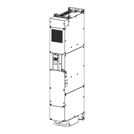
Page 113: Outline Dimension Drawings
Outline dimension drawings FR-A872-05690 to 07150 50 50 50 (45) (23) (139.5) 402.5 2×Φ24 hole 4×Φ24 hole 2×Φ10 hole 4×Φ10 hole 50 50 50 (45) (148) (Unit: mm) 6. SPECIFICATIONS 6.3 Outline dimension drawings... - Page 114 Operation panel (FR-DU08, FR-LU08) Outline drawing Panel cutting dimension drawing 120 or more∗ Panel 3.2max 27.8 Operation panel Parameter unit connection cable Air- (FR-CB2[ ]) bleeding (option) hole 2-M3 screw Operation panel connection connector (FR-ADP option) ∗ Denotes the space required to connect an optional parameter unit connection cable (FR-CB2[ ]).
- Page 115 MEMO 6. SPECIFICATIONS 6.3 Outline dimension drawings...
-
Page 116: Chapter 7 Appendix
CHAPTER 7 APPENDIX Comparison with FR-A870............................116 Instructions for compliance with the EU Directives....................117 Instructions for UL and cUL ..........................120 Instructions for EAC..............................122 Restricted Use of Hazardous Substances in Electronic and Electrical Products..........123 Referenced Standard (Requirement of Chinese standardized law) ..............124... -
Page 117: Comparison With Fr-A870
APPENDIX APPENDIX provides the reference information for use of this product. Refer to APPENDIX as required. Comparison with FR-A870 Item FR-A870 FR-A872 Pr.30 Regenerative function Setting ranges: "0, 1, 100, 101" Setting ranges: "2, 10, 11, 102, 110, 111" selection Initial value: "0"... -
Page 118: Instructions For Compliance With The Eu Directives
CE marking. • The authorized representative in the EU The authorized representative in the EU is shown below. Name: Mitsubishi Electric Europe B.V. Address: Mitsubishi-Electric-Platz 1, 40882 Ratingen, Germany EMC Directive We declare that this inverter conforms with the EMC Directive and affix the CE marking on the inverter. - Page 119 • Use a tinned (plating should not include zinc) crimping terminal to connect the earth (ground) cable. When tightening the screw, be careful not to damage the threads. • For use as a product compliant with the Low Voltage Directive, use PVC cable whose size is indicated on page •...
- Page 120 This function detects the overload of the motor and shut off the inverter output by stopping the operation of the transistor at the inverter output side. (The operation characteristic is shown below.) Operational characteristic of the electronic thermal relay function Pr.9 = 50% setting Pr.9 = 100% setting *1, 2...
-
Page 121: Instructions For Ul And Cul
Instructions for UL and cUL (Standard to comply with: UL 61800-5-1, CSA 22.2 No. 274) General precaution CAUTION - Risk of Electric Shock - The bus capacitor discharge time is 10 minutes. Before starting wiring or inspection, switch power off, wait for more than 10 minutes, and check for residual voltage between terminal P/+ and N/- with a meter etc., to avoid a hazard of electrical shock. - Page 122 Short circuit ratings Suitable for use in a circuit capable of delivering not more than 100 kA rms symmetrical amperes, 600 V maximum. Motor overload protection When using the electronic thermal relay function as motor overload protection, set the rated motor current in Pr.9 Electronic thermal O/L relay.
-
Page 123: Instructions For Eac
13.) • Authorized sales representative (importer) in the CU area The authorized sales representative (importer) in the CU area is shown below. Name: Mitsubishi Electric (Russia) LLC Address: 52, bld 1 Kosmodamianskaya Nab 115054, Moscow, Russia Phone: +7 (495) 721-2070 Fax: +7 (495) 721-2071 7. -
Page 124: Restricted Use Of Hazardous Substances In Electronic And Electrical Products
Restricted Use of Hazardous Substances in Electronic and Electrical Products The mark of restricted use of hazardous substances in electronic and electrical products is applied to the product as follows based on the "Management Methods for the Restriction of the Use of Hazardous Substances in Electrical and Electronic Products"... -
Page 125: Referenced Standard
Referenced Standard (Requirement of Chinese standardized law) This Product is designed and manufactured accordance with the following Chinese standards. GB/T 16855.1 Machinery GB/T 12668.502 safety: GB 28526 GB/T 12668.3 Electrical safety: GB/T 12668.501 GB/T 12668.3 7. APPENDIX 7.6 Referenced Standard (Requirement of Chinese standardized law) - Page 126 MEMO 7. APPENDIX 7.6 Referenced Standard (Requirement of Chinese standardized law)
- Page 127 (1) Damages caused by any cause found not to be the responsibility of Mitsubishi Electric. (2) Loss in opportunity, lost profits incurred to the user by Failures of Mitsubishi Electric products. (3) Special damages and secondary damages whether foreseeable or not, compensation for accidents, and compensation for damages to products other than Mitsubishi Electric products.
- Page 128 • The copyright and other rights of the enclosed CD-ROM all belong to Mitsubishi Electric Corporation. • No part of the enclosed CD-ROM may be copied or reproduced without the permission of Mitsubishi Electric Corporation. • Specifications of the enclosed CD-ROM are subject to change for modification without notice.
- Page 129 REVISIONS *The manual number is given on the bottom left of the back cover. Revision date Manual number Revision Jul. 2019 IB(NA)-0600830ENG-A First edition IB-0600830ENG-A...
- Page 130 HEAD OFFICE: TOKYO BUILDING 2-7-3, MARUNOUCHI, CHIYODA-KU, TOKYO 100-8310, JAPAN IB(NA)-0600830ENG-A(1907)MEE Printed in Japan Specifications subject to change without notice.
Need help?
Do you have a question about the FR-A872-E and is the answer not in the manual?
Questions and answers