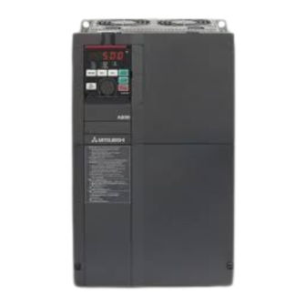
Mitsubishi Electric 800 Series Instruction Manual
Safety stop function
Hide thumbs
Also See for 800 Series:
- Instruction manual (727 pages) ,
- Instruction manual (function (534 pages) ,
- Manual (183 pages)
Advertisement
Quick Links
INVERTER
FR-A800/F800
Safety Stop Function Instruction Manual
1. GENERAL DESCRIPTION ............................................ 3
2. INSTALLATION AND WIRING...................................... 5
4. TEST AND CHECKING FAILURE ............................... 12
5. SAFETY PARAMETERS OF FR-A800/F800 ................ 13
CONTENTS
Advertisement

Summary of Contents for Mitsubishi Electric 800 Series
-
Page 1: Table Of Contents
INVERTER FR-A800/F800 Safety Stop Function Instruction Manual CONTENTS 1. GENERAL DESCRIPTION ..........3 2. INSTALLATION AND WIRING........5 3. EXAMPLE OF SAFETY SYSTEM CONFIGURATION ..9 4. TEST AND CHECKING FAILURE ....... 12 5. SAFETY PARAMETERS OF FR-A800/F800 ....13... - Page 2 The information of this manual is merely a guide for proper installation. Mitsubishi Electric Corporation. cannot assume responsibility for the compliance or the noncompliance to any code, national, local, or otherwise for the proper installation of this equipment.
-
Page 3: General Description
GENERAL DESCRIPTION Features The safety stop function of the Mitsubishi Electric FR-A800/F800 inverter can be used to prevent the inverter from supplying rotational energy to motors. (In this Instruction Manual, the STO (safe torque off) function specified in IEC 61800-5-2 is referred to as the safety stop function.) Dual input terminals S1 and S2 can be used to cut off the gate-drive power to the IGBT. - Page 4 Safety stop function with SIL 3 certification The Mitsubishi Electric FR-A800/F800 inverters now comply with safety integrity level 3 (SIL 3) of the IEC EC61508:2010 functional safety standard. • Target models Mitsubishi Electric FR-A800/F800 inverters • Change of the compliance The Mitsubishi Electric FR-A800/F800 inverters now comply with SIL 3.
-
Page 5: Installation And Wiring
IP54 and all interconnection wiring is short and protected against open and short circuit faults. Refer ISO/IEC13849-2. Installation The safety stop function of the Mitsubishi Electric FR-A800/F800 inverter should be used under the following conditions and environment. Table 2 Conditions and environment for using the safety stop function... - Page 6 Warning To avoid an electric shock hazard, insert the magnetic contactor (MC) between power source and inverter. Open the contact of MC and keep away from the inverter for discharging time (refer to your inverter’s Instruction Manual for information) before performing any work on the inverter. And verify that the voltage on the bus capacitors has discharged before measuring the DC bus voltage between terminals P(+) and N(-) or at test points (refer to your inverter’s Instruction Manual for locations).
- Page 7 Table 5 Truth table of safety related signals Output Internal Output Operation panel Inverter Input safety Input terminal signal terminal running indication power circuit status status So (SO) SAFE E.SAF Output shutoff ...
- Page 8 ●Wiring and ferrule terminal specifications Table 6 Wiring and Ferrule terminal specifications Ferrule terminal model Crimping tool name Cable gauge (mm AI 0,34-10TQ AI 0,5-10WH 0.75 AI 0,75-10GY CRIMPFOX 6 AI 1-10RD 1.25 / 1.5 AI 1,5-10BK 0.75 (for two wires) AI TWIN 2 X 0,75-10GY ...
-
Page 9: Example Of Safety System Configuration
EXAMPLE OF SAFETY SYSTEM CONFIGURATION ●FR-A800/F800 configuration example R/L1 S/L2 T/L3 So (SO) Logic RESET START STOP STOP Gate Gate Emergency ASIC Drive r Drive r IGBTs stop button +24V XS0 XS1 COM0 COM1 Internal Safety Circuit +24V S a f e t y r e l a y module M E L S E C Q S 9 0 S R 2 S N-Q PC *1 FR-A800/F800... - Page 10 ●Multiple inverter configuration example R/L1 S/L2 T/L3 So (SO) Logic RESET Gate Gate Emergency ASIC Drive r stop button Drive r IGBTs XS0 XS1 +24V COM0 COM1 Internal Safety Circuit +24V S a f e t y r e l a y module M E L S E C Q S 9 0 S R 2 S N-Q FR-A800/F800 R/L1 S/L2 T/L3...
- Page 11 Gate ASIC Driver Driver A2(0V) A2(0V) U V W Mitsubishi Electric safety controller MELSEC-WS series CPU module WS0-CPU0 Safety I/O combined module WS0-XTIO Figure 6 Safety system example of the FR-A800/F800 inverter NOTE • When starting up the system operation, press the RESET switch to reset the safety stop function first.
-
Page 12: Test And Checking Failure
TEST AND CHECKING FAILURE Caution To avoid system faults, check the safety stop function at least once per year. To comply with SIL 3, the safety stop function must be checked at least once in three months. Also, check the safety stop function at system installation, any software changes, and parameter setting changes. -
Page 13: Safety Parameters Of Fr-A800/F800
To assign the function of the SAFE signal to an output terminal, set either value shown in the following table in any of Pr.190 to Pr.196 (Output terminal function selection). Pr.190 to Pr.196 settings Output signal Positive logic Negative logic SAFE ... - Page 14 MEMO...
- Page 15 REVISIONS Revision Date Manual Number Revision Apr. 2013 BCN-A23228-001(E) First edition Edited Jun. 2013 BCN-A23228-001-A(E) ● Multiple inverter configuration example Jul. 2014 BCN-A23228-001-B(E) Compatibility with the FR-F800 series Added ● SAFE signal (2. INSTALLATION AND WIRING, 4. TEST AND May 2016 BCN-A23228-001-C(E) CHECKING FAILURE) Edited...
- Page 16 5, Mavrogenous Str. SE- 223 55 Lund GR-18542 Piraeus Phone: +46 (0) 8 625 10 00 Phone: +30 (0)211 / 1206-900 Mitsubishi Electric Turkey Elektrik Ürünleri A.Ş. TURKEY Fax: +30 (0)211 / 1206-999 Fabrika Otomasyonu Merkezi MELTRADE Kft. HUNGARY Şerifali Mahallesi Nutuk Sokak No.5 Fertő...


Need help?
Do you have a question about the 800 Series and is the answer not in the manual?
Questions and answers