Moxa Technologies MGate 5114 Series User Manual
Hide thumbs
Also See for MGate 5114 Series:
- Quick installation manual (5 pages) ,
- Quick installation manual (7 pages)

Subscribe to Our Youtube Channel
Related Manuals for Moxa Technologies MGate 5114 Series


Summary of Contents for Moxa Technologies MGate 5114 Series
- Page 1 MGate 5114 Series User Manual Version 2.1, September 2023 www.moxa.com/products © 2023 Moxa Inc. All rights reserved.
- Page 2 MGate 5114 Series User Manual The software described in this manual is furnished under a license agreement and may be used only in accordance with the terms of that agreement. Copyright Notice © 2023 Moxa Inc. All rights reserved. Trademarks The MOXA logo is a registered trademark of Moxa Inc.
-
Page 3: Table Of Contents
Table of Contents Introduction ............................5 Overview .............................. 5 Package Checklist ..........................5 Product Features ........................... 6 Hardware .............................. 7 Power Input and Relay Output Pinouts...................... 7 LED Indicators ............................7 Dimensions ............................8 Pin Assignments ............................ 8 Hardware Installation Procedure ......................9 Specifications ............................ - Page 4 Configuration (Text Mode Console) ....................59 Network Management Tool (MXstudio)....................60 SNMP Agents with MIB II and RS-232-Like Groups ................61 RFC1213 MIB-II Supported SNMP Variables .................... 61 RFC1317 RS-232-Like Groups ....................... 62...
-
Page 5: Introduction
1. Introduction Welcome to the MGate 5114 series of gateways that feature easy protocol conversion between Modbus RTU/ASCII/TCP, IEC 60870-5-101/104 protocols. This chapter is an introduction to the MGate 5114 Series. The following topics are covered in this chapter: Overview The MGate 5114 is an industrial Ethernet gateway for Modbus RTU/ASCII/TCP, IEC 60870-5-101, and IEC 61870-5-104 network communications. -
Page 6: Product Features
• • -40 to 75°C wide operating temperature models available Serial port with 2 kV built-in isolation protection • Built-in Ethernet cascading for easy wiring • Security features based on IEC-62443 standards • MGate 5114 Series User Manual... -
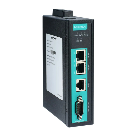
Page 7: Hardware
When the MGate 5114 acts as an IEC 60870-5-101 slave: Received a master exception (format error, checksum error, invalid data) *Only indicates serial communication status; for IEC 60870-5-104 or Modbus TCP status, please refer to the LED indicator on the Ethernet port. MGate 5114 Series User Manual... -
Page 8: Dimensions
– – – – – – – *Signal ground Ethernet Port (RJ45) Signal Console Port (RS-232) The MGate 5114 Series can use a RJ45 serial port to connect to a PC for device configuration. RS-232 MGate 5114 Series User Manual... -
Page 9: Hardware Installation Procedure
Reset Button Restore the MGate to factory default settings by using a pointed object (such as a straightened paper clip) to hold the reset button down until the Ready LED stops blinking (approx. five seconds). MGate 5114 Series User Manual... -
Page 10: Pull-High, Pull-Low, And Terminator For Rs-485
Malfunctioning MGate replacement Replace the malfunctioning MGate with a new MGate. Insert the microSD card into the new MGate. Power on the MGate. The configuration file stored on the microSD card will automatically copy to the MGate. MGate 5114 Series User Manual... - Page 11 When you replace the MGate gateway’s microSD card, the microSD card will synchronize the configurations stored on the MGate gateway. Note that the replacement microSD card should not contain any configuration files on it; otherwise, the out-of-date configuration will copy to the MGate device. MGate 5114 Series User Manual...
-
Page 12: Getting Started
The Ethernet LED maintains a solid green color when connected to a 100 Mbps Ethernet network. • The Ethernet LED maintains a solid orange color when connected to a 10 Mbps Ethernet network. • The Ethernet LED will flash when Ethernet packets are being transmitted or received. • MGate 5114 Series User Manual... -
Page 13: Installing Dsu Software
Launch DSU. You may also open the DSU through Start > Programs > MOXA > DSU. The DSU window should appear as shown below. Click Search and a new Search window will pop up. MGate 5114 Series User Manual... -
Page 14: Log In To The Web Console
When you log in the web console for the first time, a message will pop up. Emphasizing a higher security level, we suggest you to change the password. The password can be changed in the following path: System Management > Misc. Settings > Account Management. MGate 5114 Series User Manual... -
Page 15: Quick Setup
Modbus TCP Client IEC 60870-5-101 Slave Modbus TCP Client IEC 60870-5-104 Server Modbus RTU/ASCII Master IEC 60870-5-104 Server Quick Setup—System Setting First, configure the Server Settings to identify the units and Network Settings of the MGate. MGate 5114 Series User Manual... -
Page 16: Quick Setup-Select Protocol
After finishing the device protocol selection, Role 1 and Role 2 of MGate will be confirmed. You will need to configure the roles on each side by the following steps. Here is an example of Role 1 as a IEC 60870-5-104 server, and Role 2 as a Modbus RTU/ASCII master. MGate 5114 Series User Manual... - Page 17 IEC 60870-5-104 Server settings: Configure COT size, ASDU address, and Listen port. Modbus RTU/ASCII Master settings: Set Mode selection, Serial Parameters Settings and Modbus Commands. MGate 5114 Series User Manual...
-
Page 18: Quick Setup-Finish
To view IEC 60870-5-104 and Modbus mapping status, click I/O data mapping. It will go to the Protocol Settings > I/O Data Mapping page. For additional details, refer to chapter 4, Protocol Settings—I/O Data Mapping. MGate 5114 Series User Manual... -
Page 19: Web Console Configuration And Troubleshooting
You can enter a name to help you identify the unit, such as Server name (an alphanumeric string) the function, etc. You can enter a name to help you identify the unit location. Server location (an alphanumeric string) Such as “Cabinet A001.” MGate 5114 Series User Manual... -
Page 20: Network Settings
DNS server 1 This is the IP address of the primary domain name server. (or other 32-bit number) 0.0.0.0 This is the IP address of the secondary domain name DNS server 2 (or other 32-bit number) server. MGate 5114 Series User Manual... -
Page 21: Serial Settings
Configure MGate’s Role 1 and Role 2. Configure the master side first followed by the slave side. NOTE We suggest that you configure the master side first and then the slave side. After the MGate configuration is completed, click I/O data mapping to view details on exchanging data with the PSCADA. MGate 5114 Series User Manual... -
Page 22: Protocol Settings-Protocol Conversion
The MGate’s internal memory is divided into two parts—one for input and the other for output as shown in the illustration below. The internal memory concept is shown in the figure below: To learn more about MGate’s internal memory, refer to Protocol Settings—I/O Data Mapping. MGate 5114 Series User Manual... -
Page 23: Protocol Settings-Modbus Tcp Client (Master) Settings
On the MGate 5114, the Response timeout field is used to configure how long the gateway will wait for a response from a Modbus sever/slave. Refer to your device manufacturer’s documentation to manually set the response timeout MGate 5114 Series User Manual... - Page 24 Endian swap None Word Word: 0x0A, 0x0B, 0x0C, 0x0D becomes Byte and Word 0x0C, 0x0D, 0x0A, 0x0B. Byte and Word: 0x0A, 0x0B, 0x0C, 0x0D becomes 0x0D, 0x0C, 0x0B, 0x0A. Read starting 0-65535 Modbus register address. address MGate 5114 Series User Manual...
-
Page 25: Protocol Settings-Modbus Rtu/Ascii Master Settings
The user-defined values to write into the Fault value 00 00 data bits when the Set to user defined value option is selected. Defines the communication timeout for Fault timeout 100-65535 ms 6000 the opposite side. Protocol Settings—Modbus RTU/ASCII Master Settings MGate 5114 Series User Manual... - Page 26 (only for Modbus value that is not user-configurable. When the serial side RTU) of the MGate receives one character, and the next one comes after the “inter-character timeout” defined, the frame will be discarded because of timeout. MGate 5114 Series User Manual...
-
Page 27: Protocol Settings-Modbus Tcp Server (Slave) Settings
The TCP port number. Protocol Settings—Modbus RTU/ASCII Slave Settings Slave Settings Parameter Value Default Description Mode RTU or ASCII The Modbus protocol type The Modbus slave ID that this server/slave module will Slave ID 1-255 accept. MGate 5114 Series User Manual... -
Page 28: Protocol Settings-Iec 60870-5-104 Client Settings
Timeout of when to send S-format to the T2 timeout 1-3000000 ms 10000 host to acknowledge outstation messages received Timeout of sending test frame to T3 timeout 1-172800000 ms 20000 prevent from long idle state MGate 5114 Series User Manual... - Page 29 Indicate IP address of IEC 60870-5-104 IP address 255.255.255.255 0.0.0.0:2404 server that MGate connects to TCP port: 1024 - 60000 Indicate ASDU address of IEC 60870-5- ASDU address 0-65534 104 server that MGate connects to MGate 5114 Series User Manual...
- Page 30 Select/Execute mode Select/Execute Only Execute Only: Writes occur with a single command/response from the device. When connecting to an IEC 60870-5-104 server, you have to add the objects you want to collect and configure them. MGate 5114 Series User Manual...
- Page 31 Keep latest data, clear data to zero, set the data bits to user-defined values. Defines the Fault Protection Timeout 1-86400 s communication timeout for the opposite side. MGate 5114 Series User Manual...
-
Page 32: Protocol Settings-Iec 60870-5-104 Server Settings
Timeout of sending test frame to T3 timeout 1-172800000 ms 20000 prevent from long idle state Command with timestamp refers to UTC Timestamp reference Local time or Local time. MGate 5114 Series User Manual... - Page 33 Byte: 0x0A, 0x0B, 0x0C, 0x0D becomes Byte 0x0B, 0x0A, 0x0D, 0x0C Endian swap Byte Word: 0x0A, 0x0B, 0x0C, 0x0D Word Byte and Word becomes 0x0C, 0x0D, 0x0A, 0x0B. Byte and Word: 0x0A, 0x0B, 0x0C, 0x0D becomes 0x0D, 0x0C, 0x0B, 0x0A. MGate 5114 Series User Manual...
- Page 34 Measured value Event Trigger: (Normalized): 0 ~ 0xFFFF Current Reported Value > Measured value (Scaled): High Limit High Limit -32768 ~ 32767 Current Reported Value Measured value returns to below High (Floating): -999999 ~ Limit 100000000 MGate 5114 Series User Manual...
-
Page 35: Protocol Settings-Iec 60870-5-101 Master Settings
The number of retry when link confirm Link layer retries 0-255 timeout Time for master to wait before resend Offline poll period 1-2073600 s request status of link to slave after Trp timeout MGate 5114 Series User Manual... - Page 36 You can enter a name to help you Device name An alphanumeric string Device 1 identify the unit, such as the function, etc. Indicate link address of IEC 60870-5- Link address 0-65534 101 slave that the MGate connects to MGate 5114 Series User Manual...
- Page 37 Byte and Word: 0x0A, 0x0B, 0x0C, 0x0D becomes 0x0D, 0x0C, 0x0B, 0x0A. Select/Execute: Writes occur with a dual command/response from the Select/Execute, Execute device. Select/Execute mode Select/Execute Execute Only: Writes occur with a Only single command/response from the device. MGate 5114 Series User Manual...
- Page 38 Keep latest data, clear data to zero, set the data bits to user-defined values. Defines the Fault Protection Timeout 1–16777215s communication timeout for the opposite side. MGate 5114 Series User Manual...
-
Page 39: Protocol Settings-Iec 60870-5-101 Slave Settings
Set the size of the IOA address field for IOA size the relevant slave session Indicate the MGate’s link address of IEC Link address 0-65534 60870-5-101 slave Indicate the MGate’s ASDU address of ASDU address 1-65534 IEC 60870-5-101 slave MGate 5114 Series User Manual... - Page 40 If the data objects doesn’t update in a 0: Disabled period of time, the timeout will be Point Status Timeout 5 – 3600 second happened with invalid flag for the object. MGate 5114 Series User Manual...
- Page 41 Measured value (Scaled): Low Limit Low Limit 0 ~ 65535 Current Reported Value returns to above Low Limit Event Trigger: Measured value Current Reported Value - High Limit (Floating): 0 ~ Last Reported Value| > 100000000 Threshold MGate 5114 Series User Manual...
-
Page 42: Protocol Settings-Io Data Mapping
These settings are used to restrict access to the module by the IP address. Only IP addresses on the list will be allowed access to the device. The restriction difference listed as below table: (check box “Apply additional restrictions” only can be activated if “Active the accessible IP list” is activated. MGate 5114 Series User Manual... -
Page 43: System Management-Dos Defense
Users can select from several options to enable DoS Defense in order to fend off cybersecurity attacks. A denial-of-service (DoS) attack is an attempt to make a machine or a network resource unavailable. Users can select from the following options to counter DoS attacks. MGate 5114 Series User Manual... -
Page 44: System Management-System Log Settings
Warning by Email Overwrites the oldest event log Event log oversize action Stops recording event log Syslog Settings Description Syslog server IP IP address of a server which will record the log data Syslog server port MGate 5114 Series User Manual... -
Page 45: System Management-Auto Warning Settings
This field is for your mail server’s password, if required. From email address This is the email address from which automatic email warnings will be sent. To email address 1 to 4 Email addresses to which automatic email warnings will be sent. MGate 5114 Series User Manual... -
Page 46: System Management-Snmp Trap
This is a text password mechanism that is used to weakly authenticate changes Write community string to agents of managed network devices. SNMP agent version The MGate 5114 supports SNMP V1, V2c, and V3. MGate 5114 Series User Manual... -
Page 47: System Management-Lldp Settings
System Management—Certificate Use this function to load the Ethernet SSL certificate. Select or browse for the certificate file in the Select SSL certificate/key file field. This function is only available in the web console MGate 5114 Series User Manual... -
Page 48: System Management-Misc. Settings
Session Settings Value Description Maximum Login Users The number of users that can access the MGate at the same 1-10 for HTTP+HTTPS time. Auto Logout Setting 0-1440 min. Sets the auto logout time period. MGate 5114 Series User Manual... - Page 49 Admin Account admin, user account can access and modify all the settings through the web console. User account can only view the settings and can’t change anything. MGate 5114 Series User Manual...
-
Page 50: System Management-Maintenance
PC, you can use the web console to write it onto your MGate 5114. Select the desired unit from the list in the web console and click Submit to begin the process. MGate 5114 Series User Manual... -
Page 51: System Monitoring (Troubleshooting)
Protocol Status > Diagnostic page for the status of the protocol. To analyze the Modbus RTU/ACSII/TCP or IEC 60870-5-101/104 traffic in detail, view the network logs available at Protocol Status > Traffic. MGate 5114 Series User Manual... -
Page 52: System Monitoring-System Status
Ethernet link is down. You can view the relay status on this page. System Monitoring—System Status—LLDP Table You can see LLDP related information, including Port, Neighbor ID, Neighbor Port, Neighbor Port Description, and Neighbor System. MGate 5114 Series User Manual... -
Page 53: System Monitoring-Protocol Status
The MGate provides status information for Modbus RTU/ASCII/TCP, IEC 60870-5-101, and IEC 60870-5-104 troubleshooting. Verify data or packet counters to make sure the communications are running smoothly. Modbus RTU/ASCII Diagnostics (Master) Modbus RTU/ASCII Diagnostics (Slave) MGate 5114 Series User Manual... - Page 54 Modbus TCP Diagnostics (Client/Master) Modbus TCP Diagnostics (Slave/Server) IEC 60870-5-104 Diagnostics (Client) MGate 5114 Series User Manual...
- Page 55 IEC 60870-5-104 Diagnostics (Server) IEC 60870-5-101 Diagnostics (Master) MGate 5114 Series User Manual...
- Page 56 For the PCAP file specifically, it is compatible with the popular troubleshooting tool Wireshark, with which you can easily find the root cause. Here is an example of Modbus TCP and IEC 60870-5-104 traffic. Modbus TCP Traffic MGate 5114 Series User Manual...
-
Page 57: Status Monitoring
1. On the contrary, if a slave device has failed, the status value will be set to 0. Here is the Modbus address table for status monitoring. Modbus Address (Function Code 0x03) Monitor IEC 60870-5-101/104 Slave Devices 4x60000 1 to 16 devices 4x60001 17 to 32 devices MGate 5114 Series User Manual... - Page 58 IEC 60870-5- 101/104 object will turn to “invalid.’’ About the timeout settings, you configure by the following path: Protocol Settings > IEC 60870-5- 101/104 Server/Salve > Advanced Settings > Application Layer > Point Status Timeout MGate 5114 Series User Manual...
-
Page 59: Configuration (Text Mode Console)
To select the option, press the “Enter” key to go next level menu. To go previous level menu, press “Esc” key to quit. If necessary, MGate will need to restart to activate the setting. MGate 5114 Series User Manual... -
Page 60: Network Management Tool (Mxstudio)
Firmware upgrade Configuration import/export MXview LLDP for topology analysis Security View** **Security View can check the security level of devices in accordance with the IEC62443-4-2 standard. MGate 5114 supports Level 2 of the IEC-62443-4-2 standard. MGate 5114 Series User Manual... -
Page 61: Snmp Agents With Mib Ii And Rs-232-Like Groups
MGate 5114 Series User Manual... -
Page 62: Rfc1317 Rs-232-Like Groups
RFC1317 RS-232-Like Groups RS-232 MIB Async Port MIB rs232Number rs232AsyncPortIndex rs232PortIndex rs232AsyncPortBits rs232PortType rs232AsyncPortStopBits rs232PortInSigNumber rs232AsyncPortParity rs232PortOutSigNumber rs232PortInSpeed rs232PortOutSpeed Input Signal MIB Output Signal MIB rs232InSigPortIndex rs232OutSigPortIndex rs232InSigName rs232OutSigName rs232InSigState rs232OutSigState MGate 5114 Series User Manual...
Need help?
Do you have a question about the MGate 5114 Series and is the answer not in the manual?
Questions and answers