
Related Manuals for Moxa Technologies MGate 5119 Series


Summary of Contents for Moxa Technologies MGate 5119 Series
- Page 1 MGate 5119 Series Quick Installation Guide Version 1.0, December 2021 Technical Support Contact Information www.moxa.com/support 2021 Moxa Inc. All rights reserved. P/N: 1802051190010 *1802051190010*...
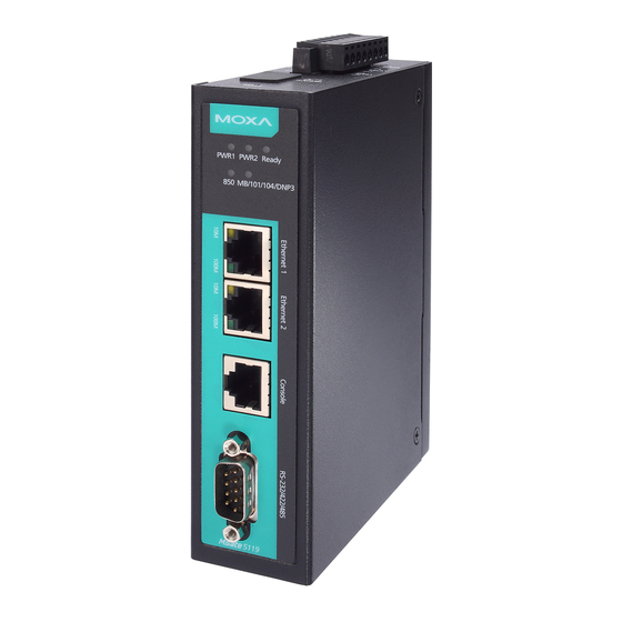
- Page 2 Overview The MGate 5119 Series is an Ethernet gateway designed for the power industry to integrate Modbus, DNP3, IEC 60870-5-101/104 devices to an IEC 61850 MMS network. Package Checklist Before installing the MGate 5119, verify that the package contains the following items: •...
- Page 3 Color Description 1. Received an outstation exception (format error, checksum error, invalid data, outstation responds are not supported) 2. Timeout (the master sent a command, but no response was received) No communication with the IEC 61850 system Green Normal IEC 61850 communication in progress When the MGate 5119 acts as an IEC 61850 server: 1.
- Page 4 Hardware Installation Procedure 1. Connect the MGate 5119's terminal block to the power supply, which could provide 12 to 48 VDC. 2. Use a serial or Ethernet cable to connect the MGate to the Modbus RTU/ASCII/TCP, DNP3 Serial/TCP, IEC60870-5-101/104 device. 3.
- Page 5 Wall-mount: NOTE The equipment is intended to be supplied by the external power source (UL listed/ IEC 60950-1/ IEC 62368-1), which output complies with ES1/SELV, PS2/LPS, output rating is 12 to 48 VDC, 0.455 A min., an ambient temperature 75°C minimum. NOTE Before connecting the Equipment to DC power inputs, make sure DC power source voltage is stable •...
- Page 6 Pin Assignments Serial Port (Male DB9) RS-422/ RS-232 RS-485 (2W) RS-485 (4W) TxD-(A) – TxD+(B) – RxD+(B) Data+(B) RxD-(A) Data-(A) – – – – – – – – – *Signal ground Ethernet Port (RJ45) Signal Power Input and Relay Output Pinouts Shielded Power Power...
Need help?
Do you have a question about the MGate 5119 Series and is the answer not in the manual?
Questions and answers