Table of Contents

Related Manuals for Aaeon AEC-6612


Summary of Contents for Aaeon AEC-6612
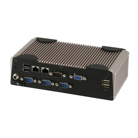
- Page 1 E m b e d d e d C o n t r o l l e r A E C - 6 6 1 2 AEC-6612 Compact Embedded Controller ® Intel Atom™ D510 1.66GHz Processor Dual LAN, 2/6 USB2.0, 2/6 COM, 1 VGA 2 PCI-Express Mini Card AEC-6612 Manual 1 November 2010...
- Page 2 AAEON assumes no liabilities resulting from errors or omissions in this document, or from the use of the information contained herein. AAEON reserves the right to make changes in the product design without notice to its users.
- Page 3 E m b e d d e d C o n t r o l l e r A E C - 6 6 1 2 Acknowledgments All other products’ name or trademarks are properties of their respective owners. • Award is a trademark of Award Software International, Inc.
- Page 4 A E C - 6 6 1 2 Packing List Before you begin operating your PC, please make sure that the following materials are enclosed: AEC-6612 Embedded Controller Wallmount Brackets Screw Package CD-ROM for manual (in PDF format) and drivers If any of these items should be missing or damaged, please contact your distributor or sales representative immediately.
- Page 5 E m b e d d e d C o n t r o l l e r A E C - 6 6 1 2 Safety & Warranty 1. Read these safety instructions carefully. 2. Keep this user's manual for later reference. 3.
- Page 6 E m b e d d e d C o n t r o l l e r A E C - 6 6 1 2 The equipment does not work well, or you cannot get it to work according to the user’s manual. The equipment has been dropped and damaged.
- Page 7 E m b e d d e d C o n t r o l l e r A E C - 6 6 1 2 Below Table for China RoHS Requirements 产品中有毒有害物质或元素名称及含量 AAEON Boxer/ Industrial System 有毒有害物质或元素 部件名称 铅...
-
Page 8: Table Of Contents
1.1 Introduction..............1-2 1.2 Features ..............1-3 1.3 Specifications ............1-4 Chapter 2 Hardware Installation 2.1 Dimension and I/O of AEC-6612....... 2-2 2.2 Location of Connectors and Jumpers of the Main Board ..................2-3 2.3 List of Jumpers ............2-5 2.4 List of Connectors ............. -
Page 9: Chapter 1 General Information
E m b e d d e d C o n t r o l l e r A E C - 6 6 1 2 Chapter General Information 1- 1 Chapter 1 General Information... -
Page 10: Introduction
-20° to 60°C. The MTBF (Mean Time Before Failure) rating states that the AEC-6612 can operate up to 50,000 hours at 40°C ambient temperature, which indicates its careful and long-life design. -
Page 11: Features
E m b e d d e d C o n t r o l l e r A E C - 6 6 1 2 1.2 Features ® Intel Atom D510 1.66 GHz Processor COM x 2 (Optional x 6), USB x 2 (Optional x 6) RS-232 x 1 (Optional x 5) Fanless Cooling System Gigabit Ethernet x 2... -
Page 12: Specifications
E m b e d d e d C o n t r o l l e r A E C - 6 6 1 2 1.3 Specifications System ® Intel Atom D510 1.66 GHz Processor Memory DDR2 400/533 SODIMM x 1, Max. 2 VGA x 1 Keyboard/Mouse Keyboard &... - Page 13 E m b e d d e d C o n t r o l l e r A E C - 6 6 1 2 Mechanical and Environmental Construction Aluminum Alloy Chassis Color Dark Gray Mounting Wallmount Dimension 7.8”(W) x 2.3”(H) x 4.3”(D) (197 mm x 57.2 mm x 110 mm) Net Weight 2.73 lb (1.24 kg)
-
Page 14: Chapter 2 Hardware Installation
E m b e d d e d C o n t r o l l e r A E C - 6 6 1 2 Chapter Hardware Installation Chapter 2 Hardware Installation... -
Page 15: Dimension And I/O Of Aec-6612
E m b e d d e d C o n t r o l l e r A E C - 6 6 1 2 2.1 Dimension and I/O of AEC-6612 COM6 LAN1 LAN2 COM1 DC IN COM2 COM3... - Page 16 E m b e d d e d C o n t r o l l e r A E C - 6 6 1 2 2.2 Connectors and Jumpers of The Main Board Component Side 2 - 3 Chapter 2 Hardware Installation...
- Page 17 E m b e d d e d C o n t r o l l e r A E C - 6 6 1 2 Solder Side 2 - 4 Chapter 2 Hardware Installation...
-
Page 18: List Of Jumpers
E m b e d d e d C o n t r o l l e r A E C - 6 6 1 2 2.3 List of Jumpers The board has a number of jumpers that allow you to configure your system to suit your application. -
Page 19: List Of Connectors
E m b e d d e d C o n t r o l l e r A E C - 6 6 1 2 2.4 List of Connectors The board has a number of connectors that allow you to configure your system to suit your application. - Page 20 E m b e d d e d C o n t r o l l e r A E C - 6 6 1 2 CN20 USB Port #3 CN21 COM Port #3 CN22 COM Port #2 CN23 Audio Line In/Out and MIC Connector CN24 RJ-45 Ethernet #2 CN25...
-
Page 21: Hard Disk Drive Installation
E m b e d d e d C o n t r o l l e r A E C - 6 6 1 2 2.5 Hard Disk Drive Installation Step 1: Unfasten the screws on the front and rear panel COM6 LAN1 LAN2... - Page 22 E m b e d d e d C o n t r o l l e r A E C - 6 6 1 2 Step 3: Fasten the four HDD screws and cover with the four black damper Black Damper Black Damper 2 - 9...
- Page 23 E m b e d d e d C o n t r o l l e r A E C - 6 6 1 2 Step 4: Assembly the HDD chassis Step 5: Assembly the damper bracket 2 - 10 Chapter 2 Hardware Installation...
- Page 24 E m b e d d e d C o n t r o l l e r A E C - 6 6 1 2 Step 6: Connect the HDD cable Step 7: Fasten the four screws on the bottom lid of AEC-6612 2 - 11 Chapter 2 Hardware Installation...
- Page 25 E m b e d d e d C o n t r o l l e r A E C - 6 6 1 2 Step 8: Fasten the two screws on the front and rear panel COM6 LAN1 LAN2 COM1 DC IN...
-
Page 26: Memory Card Installation
E m b e d d e d C o n t r o l l e r A E C - 6 6 1 2 2.6 Memory Card Installation Step 1: Unfasten the screws on the front and rear panel COM6 LAN1 LAN2... - Page 27 A E C - 6 6 1 2 Step 3: Insert the RAM at 30-degree angle to the memory slot and press Step 4: Close the bottom case of AEC-6612 and faten the four screws of the bottom lid 2 - 14...
- Page 28 E m b e d d e d C o n t r o l l e r A E C - 6 6 1 2 Step 5: Fasten the screws on the front and rear panel COM6 LAN1 LAN2 COM1 DC IN COM2...
-
Page 29: Wallmount Kit Installation
A E C - 6 6 1 2 2.7 Wallmount Kit Installation Get the brackets ready and fasten appropriate four screws on each bracket. After fastening the two brackets on the bottom lid of AEC-6612, the wallmount kit installation has been finished. 2 - 16... -
Page 30: Din Rail Kit Installation
A E C - 6 6 1 2 2.8 DIN Rail Kit Installation Get the DIN Rail kit ready and fasten the three screws to mount the DIN Rail kit to the bottom lid of AEC-6612 2 - 17 Chapter 2 Hardware Installation... -
Page 31: Chapter 3 Ami Bios Setup
E m b e d d e d C o n t r o l l e r A E C - 6 6 1 2 Chapter BIOS Setup Chapter 3 AMI BIOS Setup 3-1... -
Page 32: System Test And Initialization
3. The CMOS memory has lost power and the configuration information has been erased. The AEC-6612 CMOS memory has an integral lithium battery backup for data retention. However, you will need to replace the complete unit when it finally runs down. -
Page 33: Ami Bios Setup
E m b e d d e d C o n t r o l l e r A E C - 6 6 1 2 3.2 AMI BIOS Setup AMI BIOS ROM has a built-in Setup program that allows users to modify the basic system configuration. -
Page 34: Chapter 4 Driver Installation
E m b e d d e d C o n t r o l l e r A E C - 6 6 1 2 Chapter Driver Installation 4 - 1 Chapter 4 Driver Installation... - Page 35 E m b e d d e d C o n t r o l l e r A E C - 6 6 1 2 The AEC-6612 comes with a CD-ROM that contains all drivers and utilities that meet your needs.
- Page 36 E m b e d d e d C o n t r o l l e r A E C - 6 6 1 2 4.1 Installation: Insert the AEC-6612 CD-ROM into the CD-ROM Drive. And install the drivers from Step 1 to Step 4 in order. Step 1 – Install Chipset Driver 1.
- Page 37 E m b e d d e d C o n t r o l l e r A E C - 6 6 1 2 Step 4 – Install LAN Driver 1. Click on the STEP4-LAN folder and select the OS folder your system is 2.
-
Page 38: Appendix A Programming The Watchdog Timer
E m b e d d e d C o n t r o l l e r A E C - 6 6 1 2 Appendix Programming the Watchdog Timer Appendix A Programming the Watchdog Timer... -
Page 39: Programming
AEC-6612 utilizes W83627DHG-P chipset as its watchdog timer controller. Below are the procedures to complete its configuration and the AAEON intial watchdog timer program is also attached based on which you can develop customized program to fit your application. Configuring Sequence Description... - Page 40 E m b e d d e d C o n t r o l l e r A E C - 6 6 1 2 (3) Exit the W83627DHG config Mode. Undesired result may occur if the config Mode is not exited normally. (1) Enter the W83627DHG config Mode To enter the W83627DHG config Mode, two special I/O write operations are to be performed during Wait for Key state.
- Page 41 E m b e d d e d C o n t r o l l e r A E C - 6 6 1 2 = 010 Power LED pin is driven low. = 011 Power LED pin outputs 2Hz pulse with 50% duty cycle.
- Page 42 E m b e d d e d C o n t r o l l e r A E C - 6 6 1 2 WatchDog Timer Register II (Index=F6h, Default=00h) Bit 7-0 = 0 x 00 Time-out Disable = 0 x 01 Time-out occurs after 1 second/minute = 0 x 02 Time-out occurs after 2...
- Page 43 E m b e d d e d C o n t r o l l e r A E C - 6 6 1 2 Force Watchdog Timer time-out event: this bit is self-clearing Bit 4 : Watchdog Timer Status. R/W Watchdog Timer time-out occurred Watchdog Timer counting Bit 3-0...
-
Page 44: W83627Dhg Watchdog Timer Initial Program
E m b e d d e d C o n t r o l l e r A E C - 6 6 1 2 A.2 W83627DHG Watchdog Timer Initial Program Example: Setting 10 sec. as Watchdog timeout interval ;/////////////////////////////////////////////////////////////////////////////////////////////// Mov dx,2eh ;Enter W83627DHG config mode... - Page 45 E m b e d d e d C o n t r o l l e r A E C - 6 6 1 2 ;/////////////////////////////////////////////////////////////////////////////////////////////// Dec dx Mov al,0f5h ;CRF5 (PLED mode register) Out dx,al Inc dx In al,dx And al,not 08h ;Set second as counting unit Out dx,al...
Need help?
Do you have a question about the AEC-6612 and is the answer not in the manual?
Questions and answers