
Subscribe to Our Youtube Channel
Related Manuals for Aaeon AEC-6872


Summary of Contents for Aaeon AEC-6872
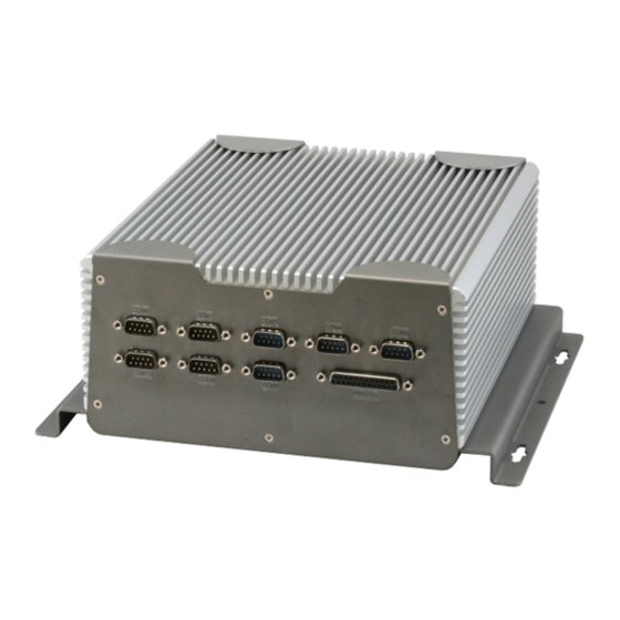
- Page 1 E m b e d d e d C o n t r o l l e r A E C - 6 8 7 2 AEC-6872 Fanless Embedded Controller ® Intel Atom D510 Processor with 2 Gigabit Ethernet 10 COMs, Audio, 4 USB 1 PCI-E or 1 PCI AEC-6872 Manual 1st Ed. April 2011...
- Page 2 AAEON assumes no liabilities resulting from errors or omissions in this document, or from the use of the information contained herein. AAEON reserves the right to make changes in the product design without notice to its users.
- Page 3 E m b e d d e d C o n t r o l l e r A E C - 6 8 7 2 Acknowledgments • Award is a trademark of Award Software International, Inc. • ™ CompactFlash is a trademark of the Compact Flash Association.
- Page 4 A E C - 6 8 7 2 Packing List Before you begin operating your PC, please make sure that the following materials have been shipped: AEC-6872 Embedded Controller Phoenix Power Connector Wallmount Brackets CD-ROM for manual (in PDF format) and...
- Page 5 E m b e d d e d C o n t r o l l e r A E C - 6 8 7 2 Safety & Warranty 1. Read these safety instructions carefully. 2. Keep this user's manual for later reference. 3.
- Page 6 E m b e d d e d C o n t r o l l e r A E C - 6 8 7 2 The equipment does not work well, or you cannot get it to work according to the user’s manual. The equipment has been dropped and damaged.
- Page 7 E m b e d d e d C o n t r o l l e r A E C - 6 8 7 2 Below Table for China RoHS Requirements 产品中有毒有害物质或元素名称及含量 AAEON Boxer/ Industrial System 有毒有害物质或元素 部件名称 铅...
-
Page 8: Table Of Contents
E m b e d d e d C o n t r o l l e r A E C - 6 8 7 2 Contents Chapter 1 General Information 1.1 Introduction..............1-2 1.2 Features ..............1-4 1.3 Specifications ............1-5 Chapter 2 Hardware Installation 2.1 Dimension .............. - Page 9 E m b e d d e d C o n t r o l l e r A E C - 6 8 7 2 Appendix B I/O Information B.1 I/O Address Map ..........B-2 B.2 Memory Address Map ..........B-4 B.3 IRQ Mapping Chart ..........B-5 B.4 DMA Channel Assignments .........B-5 viii...
-
Page 10: Chapter 1 General Information
E m b e d d e d C o n t r o l l e r A E C - 6 8 7 2 Chapter General Information 1- 1 Chapter 1 General Information... -
Page 11: Introduction
Being a control center, the AEC-6872 is suitable for public multimedia entertainment services. Equipped with a high efficiency heat conduction mechanism. The AEC-6872 is compact in size but has attractive and flexible extension capabilities such as 4 USB2.0 ports, VGA, Audio, 10 COM ports, and PCI or PCI-Express slot. - Page 12 A E C - 6 8 7 2 5 g rms. With the anti-vibration hard drive device option, the AEC-6872 can be used in high vibration environments. In addition, the AEC-6872 offers low power consumption system that while operating in ambient temperatures ranging from -10° to 55°C.
-
Page 13: Features
E m b e d d e d C o n t r o l l e r A E C - 6 8 7 2 1.2 Features • Fanless Design • ® Intel Atom™ D510 Processor • PCI-Express[x1] Slot x 1 Or PCI Slot x 1 •... -
Page 14: Specifications
E m b e d d e d C o n t r o l l e r A E C - 6 8 7 2 1.3 Specifications ® Intel Atom D510 1.6 GHz Processor ® Chipset Intel ICH8M System Memory 200-pin DDR2 SODIMM x 2, Max. - Page 15 E m b e d d e d C o n t r o l l e r A E C - 6 8 7 2 Power Requirement DC 9-30V System Cooling Passive cooling Mounting Wallmount Operating Temperature Ambient with Airflow F ~ 131 F (-10 C ~ 55...
- Page 16 E m b e d d e d C o n t r o l l e r A E C - 6 8 7 2 1- 7 Chapter 1 General Information...
-
Page 17: Chapter 2 Hardware Installation
E m b e d d e d C o n t r o l l e r A E C - 6 8 7 2 Chapter Hardware Installation Chapter 2 Hardware Installation... -
Page 18: Dimension
E m b e d d e d C o n t r o l l e r A E C - 6 8 7 2 2.1 Dimension 2 - 2 Chapter 2 Hardware Installation... -
Page 19: Com2 Ring/+5V/+12V Selection (Jp3)
2.2 COM2 Ring/+5V/+12V Selection (JP3) Function +12V Ring (Default) 2.3 Clear CMOS (JP5) Function Protected (Default) Clear 2.4 RAM Module Installation Step 1: Unfasten the two screws on the front and rear panels of AEC-6872 2 - 3 Chapter 2 Hardware Installation... - Page 20 E m b e d d e d C o n t r o l l e r A E C - 6 8 7 2 Step 2: Unfasten the six screws to release the brackets and bottom lid of AEC-6872 Step 3: Cover with a thermal pad 2 - 4...
- Page 21 E m b e d d e d C o n t r o l l e r A E C - 6 8 7 2 Step 4: Insert the RAM module to the AEC-6872 Step 5: Fasten the six screws to lock the brackets and bottom lid of...
- Page 22 E m b e d d e d C o n t r o l l e r A E C - 6 8 7 2 Step 6: Fasten the two screws on the front and rear panels of AEC-6872 2 - 6...
-
Page 23: Hdd Installation
A E C - 6 8 7 2 2.5 HDD Installation Step 1: Unfasten the two screws on the front and rear panels of AEC-6872 Step 2: Unfasten the six screws to release the brackets and bottom lid of AEC-6872... - Page 24 E m b e d d e d C o n t r o l l e r A E C - 6 8 7 2 Step 3: Fasten the four HDD screws and cover with the four black damper 2 - 8 Chapter 2 Hardware Installation...
- Page 25 E m b e d d e d C o n t r o l l e r A E C - 6 8 7 2 Step 4: Place the HDD to the HDD bracket Step 5: Assembly the damper bracket and fasten the four screws 2 - 9 Chapter 2 Hardware Installation...
- Page 26 E m b e d d e d C o n t r o l l e r A E C - 6 8 7 2 Step 6: Connect the SATA and power cables HDD DISK SATA Power W/LOCK I/O Board Side 2 - 10 Chapter 2 Hardware Installation...
- Page 27 E m b e d d e d C o n t r o l l e r A E C - 6 8 7 2 Step 7: Fasten the two screws on the front and rear panels of AEC-6872 Step 8: Fasten the six screws to release the brackets and bottom lid of...
-
Page 28: Pci-Express Card Installation
E m b e d d e d C o n t r o l l e r A E C - 6 8 7 2 2.6 PCI-Express Card Installation Step 1: Unfasten the two screws on the front and rear panels Step 2: Unfasten the six screws on the bottom lid 2 - 12 Chapter 2 Hardware Installation... - Page 29 E m b e d d e d C o n t r o l l e r A E C - 6 8 7 2 Step 3: Remove the screw with your finger and get the PCI-Express card ready to install. You should keep the shield and screw for use later. Step 4: Connect the cable 2 - 13 Chapter 2 Hardware Installation...
- Page 30 E m b e d d e d C o n t r o l l e r A E C - 6 8 7 2 Step 5: Insert the PCI-Express card into the PCI-Express slot and reattach the screw. Fasten the screw and push the tenon to lock the PCI-Express card in position.
- Page 31 E m b e d d e d C o n t r o l l e r A E C - 6 8 7 2 Step 7: Fasten the six screws on the bottom lid Step 8: Fasten the two screws on the front and rear panels 2 - 15 Chapter 2 Hardware Installation...
-
Page 32: Pci Card Installation
E m b e d d e d C o n t r o l l e r A E C - 6 8 7 2 2.7 PCI Card Installation Step 1: Unfasten the two screws on the front and rear panels Step 2: Unfasten the six screws on the bottom lid 2 - 16 Chapter 2 Hardware Installation... - Page 33 E m b e d d e d C o n t r o l l e r A E C - 6 8 7 2 Step 3: Remove the screw with your finger and get the PCI card ready to install.
- Page 34 E m b e d d e d C o n t r o l l e r A E C - 6 8 7 2 Step 5: Make sure the balance of PCI card while installing Step 6: Fasten the six screws on the bottom lid 2 - 18 Chapter 2 Hardware Installation...
- Page 35 E m b e d d e d C o n t r o l l e r A E C - 6 8 7 2 Step 7: Fasten the two screws on the front and rear panels 2 - 19 Chapter 2 Hardware Installation...
-
Page 36: Wallmount Bracket Installation
E m b e d d e d C o n t r o l l e r A E C - 6 8 7 2 2.8 Wallmount Bracket Installation Fasten the brackets with the appropriate screws. 2 - 20 Chapter 2 Hardware Installation... - Page 37 E m b e d d e d C o n t r o l l e r A E C - 6 8 7 2 Chapter BIOS Setup Chapter 3 AMI BIOS Setup 3-1...
-
Page 38: System Test And Initialization
3. The CMOS memory has lost power and the configuration information has been erased. The AEC-6872 CMOS memory has an integral lithium battery backup for data retention. However, you will need to replace the complete unit when it finally runs down. -
Page 39: Ami Bios Setup
E m b e d d e d C o n t r o l l e r A E C - 6 8 7 2 3.2 AMI BIOS Setup AMI BIOS ROM has a built-in Setup program that allows users to modify the basic system configuration. -
Page 40: Chapter 4 Driver Installation
E m b e d d e d C o n t r o l l e r A E C - 6 8 7 2 Chapter Driver Installation 4 - 1 Chapter 4 Driver Installation... - Page 41 E m b e d d e d C o n t r o l l e r A E C - 6 8 7 2 The AEC-6872 comes with a CD-ROM that contains all drivers and utilities that meet your needs.
- Page 42 E m b e d d e d C o n t r o l l e r A E C - 6 8 7 2 4.1 Installation Insert the AEC-6872 CD-ROM into the CD-ROM Drive. And install the drivers from Step 1 to Step 4 in order. Step 1 – Install Chipset Driver 1.
- Page 43 E m b e d d e d C o n t r o l l e r A E C - 6 8 7 2 Step 4 – Install LAN Driver 1. Click on the Step 4 - LAN folder and select the OS your system is 2.
-
Page 44: Appendix A Programming The Watchdog Timer
E m b e d d e d C o n t r o l l e r A E C - 6 8 7 2 Appendix Programming the Watchdog Timer Appendix A Programming the Watchdog Timer... -
Page 45: Programming
AEC-6872 utilizes W83627UHG chipset as its watchdog timer controller. Below are the procedures to complete its configuration and the AAEON intial watchdog timer program is also attached based on which you can develop customized program to fit your application. Configuring Sequence Description... - Page 46 E m b e d d e d C o n t r o l l e r A E C - 6 8 7 2 (3) Exit the W83627UHG config Mode. Undesired result may occur if the config Mode is not exited normally. (1) Enter the W83627UHG config Mode To enter the W83627UHG config Mode, two special I/O write operations are to be performed during Wait for Key state.
- Page 47 E m b e d d e d C o n t r o l l e r A E C - 6 8 7 2 0: GPIO5 is inactive. 1: GPIO5 is active. 0: WDTO# and PLED are inactive. 1: WDTO# and PLED are inactive.
- Page 48 E m b e d d e d C o n t r o l l e r A E C - 6 8 7 2 01h: Time-out occurs after 1 second/minute 02h: Time-out occurs after 2 second/minutes 03h: Time-out occurs after 3 second/minutes …………………………………………………..
-
Page 49: W83627Uhg Watchdog Timer Initial Program
E m b e d d e d C o n t r o l l e r A E C - 6 8 7 2 A.2 W83627UHG Watchdog Timer Initial Program Example: Setting 10 sec. as Watchdog timeout interval #include <stdio.h>... - Page 50 E m b e d d e d C o n t r o l l e r A E C - 6 8 7 2 // Set WatchDog time is 10 sec outportb(EFER_Port,0xf6); outportb(EFER_Port+1,0x0A); time is 10 sec outportb(EFER_Port,0xAA); exit Appendix A Programming the Watchdog Timer...
-
Page 51: Appendix B I/O Information
E m b e d d e d C o n t r o l l e r A E C - 6 8 7 2 Appendix I/O Information Appendix B I/O Information... -
Page 52: I/O Address Map
E m b e d d e d C o n t r o l l e r A E C - 6 8 7 2 B.1 I/O Address Map Appendix B I/O Information... - Page 53 E m b e d d e d C o n t r o l l e r A E C - 6 8 7 2 Appendix B I/O Information...
-
Page 54: Memory Address Map
E m b e d d e d C o n t r o l l e r A E C - 6 8 7 2 B.2 Memory Address Map Appendix B I/O Information... -
Page 55: Irq Mapping Chart
E m b e d d e d C o n t r o l l e r A E C - 6 8 7 2 B.3 IRQ Mapping Chart B.4 DMA Channel Assignments Appendix B I/O Information...
Need help?
Do you have a question about the AEC-6872 and is the answer not in the manual?
Questions and answers