
Related Manuals for Aaeon AEC-6625


Summary of Contents for Aaeon AEC-6625
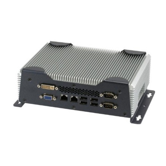
- Page 1 E m b e d d e d C o n t r o l l e r A E C - 6 6 2 5 AEC-6625 Fanless Embedded Controller ® ® Intel Core™ i7/i5/Celeron Processor Gigabit Ethernet, 6 USB, 4 COM 1 VGA, 1 DVI-D AEC-6625 Manual 3rd Ed. November 2011...
- Page 2 AAEON assumes no liabilities resulting from errors or omissions in this document, or from the use of the information contained herein. AAEON reserves the right to make changes in the product design without notice to its users.
- Page 3 E m b e d d e d C o n t r o l l e r A E C - 6 6 2 5 Acknowledgments All other products’ name or trademarks are properties of their respective owners. Award is a trademark of Award Software International, Inc.
- Page 4 E m b e d d e d C o n t r o l l e r A E C - 6 6 2 5 Packing List Before you begin operating your PC, please make sure that the following materials are enclosed: AEC-6625 Embedded Controller Wallmount Brackets Screw Package ...
- Page 5 E m b e d d e d C o n t r o l l e r A E C - 6 6 2 5 Safety & Warranty 1. Read these safety instructions carefully. 2. Keep this user's manual for later reference. 3.
- Page 6 E m b e d d e d C o n t r o l l e r A E C - 6 6 2 5 The equipment does not work well, or you cannot get it to work according to the user’s manual. The equipment has been dropped and damaged.
- Page 7 E m b e d d e d C o n t r o l l e r A E C - 6 6 2 5 ENERGY STAR ® This Product has been certified by ENERGY STAR ® ® The Regulation of ENERGY STAR : ENERGY STAR Requirements for Computer Version 5.2.
- Page 8 E m b e d d e d C o n t r o l l e r A E C - 6 6 2 5 Initiating and exiting Sleep The system set the Sleep mode after 30 minutes of inactivity when running on external power.
- Page 9 E m b e d d e d C o n t r o l l e r A E C - 6 6 2 5 Below Table for China RoHS Requirements 产品中有毒有害物质或元素名称及含量 AAEON Boxer/ Industrial System 有毒有害物质或元素 部件名称 铅...
-
Page 10: Table Of Contents
1.1 Introduction..............1-2 1.2 Features ...............1-3 1.3 Specifications .............. .1-4 Chapter 2 Hardware Installation 2.1 Dimension and I/O of AEC-6625........2-2 2.2 Location of Connectors and Jumpers of the Main Board ................... .2-6 2.3 List of Jumpers .............2-8 2.4 List of Connectors ............ - Page 11 E m b e d d e d C o n t r o l l e r A E C - 6 6 2 5 Appendix A Programming The Watchdog Timer A.1 Programming ............. .A-2 A.2 ITE8781 Watchdog Timer Initial Program ....A-6 Appendix B RAID &...
-
Page 12: Chapter 1 General Information
E m b e d d e d C o n t r o l l e r A E C - 6 6 2 5 Chapter General Information 1- 1 Chapter 1 General Information... -
Page 13: Introduction
® latest Intel processor and chipset. The cutting-edge technology has been equipped to the AEC-6625 to satisfy the versatile demands of Factory Automation, Vehicle and Marine. The AEC-6625 offers low power consumption system that while operating in ambient with airflow temperatures ranging from -20° to 60°C. -
Page 14: Features
E m b e d d e d C o n t r o l l e r A E C - 6 6 2 5 1.2 Features ® Intel QM57 Chipset Supports DVI-D x 1, VGA x 1 ... -
Page 15: Specifications
Interface — Others CompactFlash™ Slot 2.5” SATA Slim Hard Disk Drive Bay x Storage 1 (TF-AEC-6625-A3M-1010); Optional Dual 2.5” Slim Hard Disk Device Drive Kit; Optional 2.5” Slim Hard Disk Drive + Slim DVD-ROM Kit Gigabit Ethernet, RJ-45 x 2 Network —... - Page 16 E m b e d d e d C o n t r o l l e r A E C - 6 6 2 5 RJ-45 x 2 RS-232/422/485 x 1 (COM 2), RS-232 x 1 Serial Port (TF-AEC-6625-A1M-1010); RS-232 x 3 (TF-AEC-6625-A2M/A3M-1010) — Audio Line-in/ Line-out x 1 —...
- Page 17 E m b e d d e d C o n t r o l l e r A E C - 6 6 2 5 5 g rms/5~500 Hz/ random operation (CFD); Anti-Vibration 1 g rms/5~500 Hz/ random operation (HDD) 50 G peak acceleration (11 msec, duration)-CFD...
-
Page 18: Chapter 2 Hardware Installation
E m b e d d e d C o n t r o l l e r A E C - 6 6 2 5 Chapter Hardware Installation Chapter 2 Hardware Installation... -
Page 19: Dimension And I/O Of Aec-6625
E m b e d d e d C o n t r o l l e r A E C - 6 6 2 5 2.1 Dimension and I/O of AEC-6625 AEC-6625-A1/A2 Connector of AEC-6625-A1 (Front) 2 - 2... - Page 20 E m b e d d e d C o n t r o l l e r A E C - 6 6 2 5 Connector of AEC-6625-A1 (Rear) Connector of AEC-6625-A2 (Front) Connector of AEC-6625-A2 (Rear) 2 - 3...
- Page 21 E m b e d d e d C o n t r o l l e r A E C - 6 6 2 5 AEC-6625-A3 Connectors of AEC-6625-A3 (Front) 2 - 4 Chapter 2 Hardware Installation...
- Page 22 E m b e d d e d C o n t r o l l e r A E C - 6 6 2 5 Connectors of AEC-6625-A3 (Rear) 2 - 5 Chapter 2 Hardware Installation...
- Page 23 E m b e d d e d C o n t r o l l e r A E C - 6 6 2 5 2.2 Connectors and Jumpers of The Main Board Component Side 2 - 6 Chapter 2 Hardware Installation...
- Page 24 E m b e d d e d C o n t r o l l e r A E C - 6 6 2 5 Solder Side 2 - 7 Chapter 2 Hardware Installation...
-
Page 25: List Of Jumpers
E m b e d d e d C o n t r o l l e r A E C - 6 6 2 5 2.3 List of Jumpers The board has a number of jumpers that allow you to configure your system to suit your application. - Page 26 E m b e d d e d C o n t r o l l e r A E C - 6 6 2 5 Touch Panel Connector CN11 RS-232 Serial Port 1 Connector CN12 Display Port Connector CN13 UIM Connector CN14 PCI-104 Connector...
-
Page 27: Rs-232/422/485 Serial Port Connector (Com 2)
E m b e d d e d C o n t r o l l e r A E C - 6 6 2 5 2.5 RS-232/422/485 Serial Port Connector (COM 2) Signal Signal DCD (422TXD-/485DATA-) RXD (422RXD+) TXD (422TXD+/485DATA+) DTR (422RXD-) RI/+5V/+12V Selection COM2 RI/+5V/+12V Selection (JP6) -
Page 28: Compactflash™ Card Installation
E m b e d d e d C o n t r o l l e r A E C - 6 6 2 5 2.6 CompactFlash™ Card Installation Step 1: Unfasten the two screws of the CompactFlash™ Bracket Step 2: Insert the CompactFlash™... -
Page 29: Hard Disk Drive (Hdd) Installation
E m b e d d e d C o n t r o l l e r A E C - 6 6 2 5 2.7 Hard Disk Drive (HDD) Installation For A1/A2 Version Step 1: Get the HDD and HDD Bracket ready. Fasten the four screws to fix the HDD and HDD bracket Step 2: Connect the SATA cable to the HDD 2 - 12... - Page 30 A E C - 6 6 2 5 Step 3: Fasten the four screws to fix the HDD backet with the bottom case of AEC-6625 Step 4: Close the bottom cover of the AEC-6625 and fasten the screw 2 - 13 Chapter 2 Hardware Installation...
- Page 31 A E C - 6 6 2 5 Step 5: Fasten the screw to finish the installation For A3 Version Step 1: Unfasten the four screws to release the brackets from the AEC-6625 2 - 14 Chapter 2 Hardware Installation...
- Page 32 A E C - 6 6 2 5 Step 2: Unfasten the six screws to release the bottom case of the AEC-6625 Step 3: Get the HDD and HDD Bracket ready. Fasten the four screws to fix the HDD and HDD bracket...
- Page 33 A E C - 6 6 2 5 Step 4: Fasten the four screws to fix the HDD bracket with the bottom case of AEC-6625 Step 5: Get the PCI-104 card ready and fasten the four screws to install the...
- Page 34 E m b e d d e d C o n t r o l l e r A E C - 6 6 2 5 Step 6: Close the bottom case of AEC-6625 and fasten the six screws Step 7: Fasten the four screws to install the two bracket...
-
Page 35: Memory Card Installation
A E C - 6 6 2 5 2.8 Memory Card Installation Step 1: Unfasten the four screws to release the brackets from the AEC-6625 Step 2: Unfasten the five screws to release the bottom cover of the AEC-6625 2 - 18... - Page 36 E m b e d d e d C o n t r o l l e r A E C - 6 6 2 5 Step 3: Insert the RAM at 30-degree angle to the memory slot and press Step 3: Adhere the heat spreading pad to the RAM 2 - 19 Chapter 2 Hardware Installation...
-
Page 37: Wallmount Kit Installation
2.9 Wallmount Kit Installation Get the brackets ready and fasten appropriate four screws on each bracket. After fastening the two brackets on the bottom lid of AEC-6625, the wallmount kit installation has been finished. 2 - 20 Chapter 2 Hardware Installation... -
Page 38: Chapter 3 Award Bios Setup
E m b e d d e d C o n t r o l l e r A E C - 6 6 2 5 Chapter Award BIOS Setup Chapter 3 Award BIOS Setup 3-1... - Page 39 3. The CMOS memory has lost power and the configuration information has been erased. The AEC-6625 CMOS memory has an integral lithium battery backup for data retention. However, you will need to replace the complete unit when it finally runs down.
- Page 40 E m b e d d e d C o n t r o l l e r A E C - 6 6 2 5 3.2 Award BIOS Setup Awards BIOS ROM has a built-in Setup program that allows users to modify the basic system configuration.
- Page 41 Save CMOS value changes to CMOS and exit setup. Exit Without Saving Abandon all CMOS value changes and exit setup. You can refer to the "AAEON BIOS Item Description.pdf" file in the DVD for the meaning of each setting in this chapter. Chapter 3 Award BIOS Setup 3-4...
-
Page 42: Chapter 4 Driver Installation
E m b e d d e d C o n t r o l l e r A E C - 6 6 2 5 Chapter Driver Installation Chapter 4 Driver Installation... - Page 43 E m b e d d e d C o n t r o l l e r A E C - 6 6 2 5 The AEC-6625 comes with a DVD-ROM that contains all drivers that you need. Follow the sequence below to install the drivers: Step 1 –...
- Page 44 E m b e d d e d C o n t r o l l e r A E C - 6 6 2 5 4.1 Installation Insert the AEC-6625 DVD-ROM into the DVD-ROM Drive. And install the drivers from Step 1 to Step 6 in order. Step 1 – Install Chipset Driver 1.
- Page 45 E m b e d d e d C o n t r o l l e r A E C - 6 6 2 5 3. The system will help you to install the driver automatically Step 5 – Install AUDIO Driver 1.
-
Page 46: Appendix A Programming The Watchdog Timer
E m b e d d e d C o n t r o l l e r A E C - 6 6 2 5 Appendix Programming the Watchdog Timer Appendix A Programming the Watchdog Timer A-1... -
Page 47: Programming
E m b e d d e d C o n t r o l l e r A E C - 6 6 2 5 A.1 Programming AEC-6625 utilizes ITE 8781 chipset as its watchdog timer controller. Below are the procedures to complete its configuration and the AAEON initial watchdog timer program is also attached based on which you can develop customized program to fit your application. - Page 48 E m b e d d e d C o n t r o l l e r A E C - 6 6 2 5 There are three steps to complete the configuration setup: (1) Enter the MB PnP Mode; (2) Modify the data of configuration registers; (3) Exit the MB PnP Mode.
- Page 49 E m b e d d e d C o n t r o l l e r A E C - 6 6 2 5 WatchDog Timer Configuration Registers Configure Control (Index=02h) This register is write only. Its values are not sticky; that is to say, a hardware reset will automatically clear the bits, and does not require the software to clear them.
- Page 50 E m b e d d e d C o n t r o l l e r A E C - 6 6 2 5 Watch Dog Timer 1, 2, 3 Configuration Register (Index=72h, 82h, 92h Default=001s0000b) Watch Dog Timer 1,2,3 Time-Out Value (LSB) Register (Index=73h,83h,93h, Default=38h) Watch Dog Timer 1,2,3 Time-Out Value (MSB) Register (Index=74h,84h,94h Default=00h)
-
Page 51: Ite8781 Watchdog Timer Initial Program
E m b e d d e d C o n t r o l l e r A E C - 6 6 2 5 A.2 ITE8781 Watchdog Timer Initial Program .MODEL SMALL .CODE Main: CALL Enter_Configuration_mode CALL Check_Chip mov cl, 7 call Set_Logic_Device ;time setting... - Page 52 E m b e d d e d C o n t r o l l e r A E C - 6 6 2 5 call Superio_Set_Reg ; game port enable mov cl, 9 call Set_Logic_Device Initial_OK: CALL Exit_Configuration_mode MOV AH,4Ch INT 21h Enter_Configuration_Mode PROC NEAR...
- Page 53 E m b e d d e d C o n t r o l l e r A E C - 6 6 2 5 CALL Write_Configuration_Data Exit_Configuration_Mode ENDP Check_Chip PROC NEAR MOV AL,20h CALL Read_Configuration_Data CMP AL,87h JNE Not_Initial MOV AL,21h CALL Read_Configuration_Data CMP AL,81h...
- Page 54 E m b e d d e d C o n t r o l l e r A E C - 6 6 2 5 OUT DX,AL MOV DX,WORD PTR CS:[Cfg_Port+06h] IN AL,DX Read_Configuration_Data ENDP Write_Configuration_Data PROC NEAR MOV DX,WORD PTR CS:[Cfg_Port+04h] OUT DX,AL XCHG AL,AH MOV DX,WORD PTR CS:[Cfg_Port+06h]...
- Page 55 E m b e d d e d C o n t r o l l e r A E C - 6 6 2 5 Set_Logic_Device proc near push ax push cx xchg al,cl mov cl,07h call Superio_Set_Reg pop cx pop ax Set_Logic_Device endp ;Select 02Eh->Index Port, 02Fh->Data Port...
- Page 56 E m b e d d e d C o n t r o l l e r A E C - 6 6 2 5 Appendix RAID & AHCI Settings Appendix B RAID & AHCI Settings...
-
Page 57: Setting Raid
E m b e d d e d C o n t r o l l e r A E C - 6 6 2 5 B.1 Setting RAID OS installation to setup RAID Mode Step 1: Copy the files below from “Driver DVD -> Raid Driver -> F6 Floppy - x86”... - Page 58 E m b e d d e d C o n t r o l l e r A E C - 6 6 2 5 Step 3: The setting procedures “ In BIOS Setup Menu” A: Advanced -> SATA Configuration -> SATA Mode -> RAID Mode Step 4: The setting procedures “In BIOS Setup Menu”...
- Page 59 E m b e d d e d C o n t r o l l e r A E C - 6 6 2 5 Step 5: The setting procedures “In BIOS Setup Menu” C: Boot -> Boot Option #1 -> DVD-ROM Type Step 6: The setting procedures “In BIOS Setup Menu”...
- Page 60 E m b e d d e d C o n t r o l l e r A E C - 6 6 2 5 Step 7: Press Ctrl-I to enter MAIN MENU Step 8: Choose “1.Create RAID Volume” Appendix B RAID &...
- Page 61 E m b e d d e d C o n t r o l l e r A E C - 6 6 2 5 Step 9: RAID Level -> RAID0(Stripe) Step 10: Choose “Create Volume” Appendix B RAID & AHCI Settings...
- Page 62 E m b e d d e d C o n t r o l l e r A E C - 6 6 2 5 Step 11: Choose “Y” Step 12: Choose “5. Exit” Appendix B RAID & AHCI Settings...
- Page 63 E m b e d d e d C o n t r o l l e r A E C - 6 6 2 5 Step 13: Choose “Y” Step 14: Setup OS Appendix B RAID & AHCI Settings...
- Page 64 E m b e d d e d C o n t r o l l e r A E C - 6 6 2 5 Step 15: Press “F6” Step 16: Choose “S” Appendix B RAID & AHCI Settings...
- Page 65 E m b e d d e d C o n t r o l l e r A E C - 6 6 2 5 Step 17: Choose “Intel(R) ICH8M-E/ICH9M-E/5 Series SATA RAID Controller” Step 18: It will show the model number you select and then press “ENTER” B-10 Appendix B RAID &...
- Page 66 E m b e d d e d C o n t r o l l e r A E C - 6 6 2 5 Step 19: Setup is starting Windows B-11 Appendix B RAID & AHCI Settings...
-
Page 67: Setting Ahci
E m b e d d e d C o n t r o l l e r A E C - 6 6 2 5 B.2 Setting AHCI OS installation to setup AHCI Mode Step 1: Copy the files below from “Driver DVD -> Raid Driver -> F6 Floppy - x86”... - Page 68 E m b e d d e d C o n t r o l l e r A E C - 6 6 2 5 Step 3: The setting procedures “ In BIOS Setup Menu” A: Advanced -> SATA Configuration -> SATA Configuration -> SATA Mode ->...
- Page 69 E m b e d d e d C o n t r o l l e r A E C - 6 6 2 5 Step 5: The setting procedures “In BIOS Setup Menu” C: Save & Exit -> Save Changes and Exit Step 6: Setup OS B-14 Appendix B RAID &...
- Page 70 E m b e d d e d C o n t r o l l e r A E C - 6 6 2 5 Step 7: Press “F6” Step 8: Choose “S” B-15 Appendix B RAID & AHCI Settings...
- Page 71 E m b e d d e d C o n t r o l l e r A E C - 6 6 2 5 Step 9: Choose “Intel(R) 5 Series 6 Port SATA AHCI Controller” tep 10: It will show the model number you select and then press “ENTER” B-16 Appendix B RAID &...
- Page 72 E m b e d d e d C o n t r o l l e r A E C - 6 6 2 5 Step 11: Setup is loading files B-17 Appendix B RAID & AHCI Settings...
Need help?
Do you have a question about the AEC-6625 and is the answer not in the manual?
Questions and answers