Table of Contents
Advertisement
Quick Links
To learn more about EMAC's products and services and how they can help your project
http://ftp.emacinc.com/Tech_Info/About_EMAC_Products_and_Services.pdf
Authorized Distributor, Integrator, and Value-Added Reseller
Manual downloaded from
ftp.emacinc.com
For purchase information please contact
info@emacinc.com
For technical support please submit a ticket at
www.emacinc.com/support
Advertisement
Table of Contents

Subscribe to Our Youtube Channel
Related Manuals for Aaeon AEC-6840


Summary of Contents for Aaeon AEC-6840
- Page 1 To learn more about EMAC’s products and services and how they can help your project http://ftp.emacinc.com/Tech_Info/About_EMAC_Products_and_Services.pdf Authorized Distributor, Integrator, and Value-Added Reseller Manual downloaded from ftp.emacinc.com For purchase information please contact info@emacinc.com For technical support please submit a ticket at www.emacinc.com/support...
- Page 2 E m b e d d e d C o n t r o l l e r AEC-6840 Fanless Embedded Controller ® ® Intel ULV Celeron 400/650MHz EBGA CPU With Dual Ethernet, 4 COMs, DIO, ™ CompactFlash AEC-6840 Manual 1st Ed. Jan. 2005 AEC-6840 User Manual...
-
Page 3: Copyright Notice
We reserve the right to make changes in the product design without notice to its users. AEC-6840 User Manual... -
Page 4: Acknowledgments
Compact Flash Association. ™ ™ • VIA Eden is a trademark of VIA Technology Inc. ® • Microsoft Windows is a registered trademark of Microsoft Corp. • PC/AT, PS/2, and VGA are trademarks of International Business Machines Corporation. AEC-6840 User Manual... -
Page 5: Packing List
E m b e d d e d C o n t r o l l e r Packing List Before you begin operating your PC, please make sure that the following materials have been shipped: • 1 AEC-6840 Embedded Controller • 1 Keyboard & mouse cable • 1 Phoenix Power Connector •... -
Page 6: Safety & Warranty
12. Never pour any liquid into an opening. This could cause fire or electrical shock. 13. Never open the equipment. For safety reasons, only qualified service personnel should open the equipment. 14. If any of the following situations arises, get the equipment checked AEC-6840 User Manual... -
Page 7: Fcc Safety
Caution: It may cause danger of explosion if battery is incorrectly replaced. Replace only with the same or equivalent type recommended by the manufacturer. Dispose of used batteries according to the manufacturer’ s instructions. AEC-6840 User Manual... -
Page 8: Table Of Contents
2.6 Wall-mount Installation ..........28 2.7 Din Rail Installation ..29 2.8 COM2 RS-232/422/485 Serial Port Connector ....29 2.9 COM1/3/4 RS-232 Serial Port Connector Chapter 3 Award BIOS Setup.....30 ......... 31 3.1 System test and initialization AEC-6840 User Manual... - Page 9 3.13 Save & Exit Setup ..........51 3.14 Exit without saving Chapter 4 Driver Installation ....52 ........... 54 4.1 Installation procedure Aappendix A Programming the Watchdog Timer .........56 ............57 A.1 Programming ... 61 A.2 W83697UF Watchdog Timer Initial Program AEC-6840 User Manual...
-
Page 10: Chapter 1 General Information
RUGGED SIB A E C - 6 8 4 0 E m b e d d e d C o n t r o l l e r Chapter General Information AEC-6840 User Manual... -
Page 11: Introduction
E m b e d d e d C o n t r o l l e r 1.1 Introduction AEC-6840 is the advanced upgraded version of AEC-6810. The target markets are industrial automation such as applications in factory management, building entrance guard and transportation system. We primarily focuses AEC-6840 on environmental monitoring system. -
Page 12: Feature
4 serial ports / Digital IO / USB2.0 • Embedded OS WinCE.net 4.2 porting ready for application ™ • Supports CompactFlash Memory and lockable mechanism • Anti-vibration up to 5 g rms / Anti-shock up to 100gn AEC-6840 User Manual... -
Page 13: Specification
Power Supply: DC Input: 9V ~30V AC Input: External Power Adapter (Optional) • System Control: Power on / off switch x 1 Reset button x 1 • Indicator: Power LED x 1 HDD active LED x 1 AEC-6840 User Manual... - Page 14 Operation Humidity: 5~95%@40C, non-condensing • Vibration: 5 g rms / 5~500Hz / random operation (Without HDD Module) 1 g / 5~500Hz / random operation (With HDD Module) • Shock: 100g peak acceleration (11 msec. duration) • EMC: CE/FCC Class A AEC-6840 User Manual...
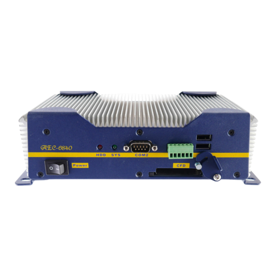
- Page 15 With lockable design for anti- vibration purpose Rear Side Serial Port x 3 Ethernet D-sub 9 Pin RJ45, 10/100 or RS-232 gigabit Reset Power Inlet Phoenix Connector 2 Pin DC 9~30V / GND Ethernet D-sub 15pin RJ45, 10/100 KB/Mouse Mini-DIN 6pin AEC-6840 User Manual...
-
Page 16: Chapter 2 Hardware Installation
RUGGED SIB A E C - 6 8 4 0 E m b e d d e d C o n t r o l l e r Chapter Hardware Installation AEC-6840 User Manual... -
Page 17: Dimension
E m b e d d e d C o n t r o l l e r 2.1 Dimension 240.0 222.0 212.2 AEC-6840 Units:mm O5.0 LAN2 COM4 COM3 DC-IN AEC-6840 RESET HDD SYS COM2 Power LAN1 COM1 KB/MS 120.0 AEC-6840 User Manual... -
Page 18: Hdd Module Installation
E m b e d d e d C o n t r o l l e r 2.2 HDD Module Installation Cable Insertion Step 1: Open the HDD cover by loosening the screws on the bottom of the chassis. AEC-6840 User Manual... - Page 19 A E C - 6 8 4 0 E m b e d d e d C o n t r o l l e r Step 2: Insert the Cable to the bottom of the chassis as the illustration below. PIN 1 AEC-6840 User Manual...
- Page 20 E m b e d d e d C o n t r o l l e r HDD Kit Combination Get the HDD and bracket ready. Bracket Step 1: Stack the HDD and bracket. Fasten HDD and bracket with the screws. AEC-6840 User Manual...
- Page 21 E m b e d d e d C o n t r o l l e r Step 2: Fasten the HDD module into the HDD kit house. Step 3: Insert the other side of the cable to the HDD module. AEC-6840 User Manual...
- Page 22 E m b e d d e d C o n t r o l l e r Step 4: Combine the HDD kit house with the chassis and push as the illustration shown below. Push Step 5: Lock with the screws. AEC-6840 User Manual...
-
Page 23: Sdram Installation
A E C - 6 8 4 0 E m b e d d e d C o n t r o l l e r 2.3 SDRAM Installation Step 1: Screw the lid off the chassis. AEC-6840 User Manual... - Page 24 E m b e d d e d C o n t r o l l e r Step 2: Remove the lid after you screw the lid off the chassis and insert the DDR SDRAM SODIMM module into the slot. SDRAM SODIMM module AEC-6840 User Manual...
-
Page 25: Com2 Rs-232/422/485 Setting
RS-232/422/485 Selection (JP2 & JP3) The following table provides the user to set up COM2 port. Function 1-2, 4-5, 7-8, 10-11 RS-232 (Default) 2-3, 5-6, 8-9, 11-12 RS-422 2-3, 5-6, 8-9, 11-12 RS-485 Function RS-232 (Default) RS-422 RS-485 Magnification AEC-6840 User Manual... -
Page 26: Power Linkage Installation
E m b e d d e d C o n t r o l l e r 2.5 Power Linkage Installation Step 1: Get the cable and connector ready Step2: Fix the connector to the cable with the screws. AEC-6840 User Manual... - Page 27 E m b e d d e d C o n t r o l l e r Step3: Insert the power cable in. Step 4: Screw the power cable into the chassis. Notice: Please make sure that pin assignment of Power and Ground on the accurate location. AEC-6840 User Manual...
-
Page 28: Wall-Mount Installation
A E C - 6 8 4 0 E m b e d d e d C o n t r o l l e r 2.6 Wall-mount Installation Fasten the brackets with the screws. Bracket Bracket AEC-6840 User Manual... -
Page 29: Din Rail Installation
2.7 Din Rail Installation Step 1: Fix the Din Rail kit with the screws on the chassis as the illustration shown. Din Rail Kit Step 2: Press the Din Rail on the Din Rail kit to fix it. Din Rail AEC-6840 User Manual... -
Page 30: Com2 Rs-232/422/485 Serial Port Connector
If you are having problems with a serial device, be sure to check the pin assignments below for the connector. Signal Signal DCD (422TXD-/485DATA-) RXD (422RXD+) TXD (422TXD+/485DATA+) DTR (422RXD-) N.C. 2.9 COM1/3/4 RS-232 Serial Port Connector Signal Signal N.C. AEC-6840 User Manual... -
Page 31: Chapter 3 Award Bios Setup
RUGGED SIB A E C - 6 8 4 0 E m b e d d e d C o n t r o l l e r Chapter Award BIOS Setup AEC-6840 User Manual... -
Page 32: System Test And Initialization
There are three situations in which you will need to change the CMOS settings: You are starting your system for the first time You have changed the hardware attached to your system The CMOS memory has lost power and the configuration information has been erased. AEC-6840 User Manual... - Page 33 E m b e d d e d C o n t r o l l e r The AEC-6840 CMOS memory has an integral lithium battery backup for data retention. However, you will need to replace the complete unit when it finally runs down.
-
Page 34: Award Bios Setup
DRAM timings, AGP functions etc. Integrated Peripherals Use this menu to specify your settings for integrated peripherals. (Onchip IDE device, Onchip PCI device, Super IO device, mouse etc.) Power Management Setup Use this menu to specify your settings for power management. AEC-6840 User Manual... - Page 35 Set Password Change / Set / Disable password. Save and Exit Setup Save the changes you’ ve made to CMOS and exit setup. Exit Without Saving Abandon all CMOS value changes and exit setup. AEC-6840 User Manual...
-
Page 36: Main Menu
Main Menu allows users to configure system components such as date, time, hard disk drive, floppy drive and display. Once a field is highlighted, on-line help information is displayed in the right box of the Menu screen. Ø IDE Primary Master AEC-6840 User Manual... - Page 37 RUGGED SIB A E C - 6 8 4 0 E m b e d d e d C o n t r o l l e r Ø IDE Primary Slave Ø CompactFlash Type AEC-6840 User Manual...
-
Page 38: Advanced Bios Features
E m b e d d e d C o n t r o l l e r 3.4 Advanced BIOS Features By choosing Advanced BIOS Features, the screen below is displayed. This sample screen contains the manufacturer’ s default values for the AEC-6840. AEC-6840 User Manual... -
Page 39: Advanced Chipset Features
E m b e d d e d C o n t r o l l e r 3.5 Advanced Chipset Features By choosing the Advanced Chipset Features, the screen below is displayed. This sample screen contains the manufacturer’ s default values for the AEC- 6840. AEC-6840 User Manual... - Page 40 RUGGED SIB A E C - 6 8 4 0 E m b e d d e d C o n t r o l l e r Ø DRAM Clock/Drive Control Ø AGP & P2P Bridge Control AEC-6840 User Manual...
-
Page 41: Integrated Peripherals
E m b e d d e d C o n t r o l l e r 3.6 Integrated Peripherals By choosing the Integrated, the screen below is displayed. This sample screen contains the manufacturer’ s default values for the AEC-6840. Ø OnChip IDE Device AEC-6840 User Manual... - Page 42 RUGGED SIB A E C - 6 8 4 0 E m b e d d e d C o n t r o l l e r Ø OnChip PCI Device Ø Super IO Device AEC-6840 User Manual...
- Page 43 RUGGED SIB A E C - 6 8 4 0 E m b e d d e d C o n t r o l l e r Ø Digital IO Setting AEC-6840 User Manual...
-
Page 44: Power Management Setup
E m b e d d e d C o n t r o l l e r 3.7 Power Management Setup By choosing the Power Management Setup, the screen below is displayed. This sample screen contains the manufacturer’ s default values for the AEC- 6840. AEC-6840 User Manual... - Page 45 RUGGED SIB A E C - 6 8 4 0 E m b e d d e d C o n t r o l l e r Ø IRQ/Event Activity Detect Ø IRQ Activity Monitoring AEC-6840 User Manual...
-
Page 46: Pnp/Pci Configuration
E m b e d d e d C o n t r o l l e r 3.8 PnP/PCI configuration By choosing the PnP/PCI configurations, the screen below is displayed. This sample screen contains the manufacturer’ s default values for the AEC- 6840. AEC-6840 User Manual... -
Page 47: Pc Health Status
E m b e d d e d C o n t r o l l e r 3.9 PC Health Status By choosing the PC Health Status, the screen below is displayed. This sample screen contains the manufacturer’ s default values for the AEC-6840. AEC-6840 User Manual... -
Page 48: Clk/Voltage Control
E m b e d d e d C o n t r o l l e r 3.10 Clk/Voltage control By choosing the Clk/Voltage Control, the screen below is displayed. This sample screen contains the manufacturer’ s default values for the AEC-6840. AEC-6840 User Manual... -
Page 49: Load Optimized Defaults
3.11 Load Optimized Defaults When you press <Enter> on this item you get a confirmation dialog box: Load Optimized Defaults (Y/N)? Pressing "Y" loads the default values that are manufacturer’ s settings for optimal performance system operations. AEC-6840 User Manual... -
Page 50: Set Password
Press ESC key if you want to exit the screen where you have been. NOTE: To clear the password, simply press Enter when asked to enter a password. Then the password function is disabled. AEC-6840 User Manual... -
Page 51: Save & Exit Setup
CMOS memory. The microprocessor will check this every time you turn on your system and compare this to what it finds as it checks the system. This record is required for the system to operate. AEC-6840 User Manual... -
Page 52: Exit Without Saving
E m b e d d e d C o n t r o l l e r 3.14 Exit without saving Selecting this option and pressing <Enter> allows you to exit the Setup program without recording any new value or changing old one. AEC-6840 User Manual... -
Page 53: Chapter 4 Driver Installation
RUGGED SIB A E C - 6 8 4 0 E m b e d d e d C o n t r o l l e r Chapter Driver Installation AEC-6840 User Manual... - Page 54 A E C - 6 8 4 0 E m b e d d e d C o n t r o l l e r The AEC-6840 comes with a CD-ROM that contains all drivers and utilities that meet your needs.
-
Page 55: Installation Procedure
A E C - 6 8 4 0 E m b e d d e d C o n t r o l l e r Insert the AEC-6840 CD-ROM into the CD-ROM Drive. And install the drivers from Step 1 to Step 5 in order. - Page 56 6. Follow the wizard and then mark “ ” only. Specify a location 7. Browse the path to CD-ROM: \ Driver\ Step 5 - Ethernet Driver \ Manual Setup - W2K (For Windows 2000) OR (For Windows XP) winxp – rtlnic (611) AEC-6840 User Manual...
-
Page 57: Watchdog Timer
RUGGED SIB A E C - 6 8 4 0 E m b e d d e d C o n t r o l l e r Appendix Programming the Watchdog Timer AEC-6840 User Manual... -
Page 58: Programming
E m b e d d e d C o n t r o l l e r A.1 Programming AEC-6840 utilizes Winbond W83697UF chipset as its watchdog timer controller. Below are the procedures to complete its configuration and the initial watchdog timer program is also attached based on which you can develop customized program to fit your application. - Page 59 -o 4e 87 -o 4e 07 logic device register -o 4f 08 logic device number -o 4e f3 select register CRF3 -i 4f read F1 value F3 value;Bit 2=0 ----second 1 ----minute -o 4e f4 select register CRF4 AEC-6840 User Manual...
- Page 60 Port 6 out Bit6 Port 7 out Bit7 Port 8 out You can try the AEC-6840 digital IO interface with some simple tests using DEBUG commands. Some examples are listed as below: -o 4e 87 Enter W83697UF configuration mode -o 4e 87...
- Page 61 "high" to port 5 and port 6 -i 280 if input port 1 to "low”, and then you can read data become to 0e if input port 2 to "low”, and then you can read data become to 0d AEC-6840 User Manual...
-
Page 62: W83697Uf Watchdog Timer Initial Program
------Select CRF3 (Set unit to minute or second) al,0f3h 4eh,al al,4fh al,11111011b ;bit 2 :0-> second :1-> minute ;Select second in this example ------Select CRF4 (Set timeout value) al,0f4h 4eh,al al,0ah ;10 seconds in this example ;Set this value to 0 disable timeout 4fh,al AEC-6840 User Manual... - Page 63 RUGGED SIB A E C - 6 8 4 0 E m b e d d e d C o n t r o l l e r ------Exit configuration mode al,0aah 4eh,al AEC-6840 User Manual...
Need help?
Do you have a question about the AEC-6840 and is the answer not in the manual?
Questions and answers