Table of Contents
Advertisement
Quick Links
Advertisement
Table of Contents

Related Manuals for Aaeon AEC-6877


Summary of Contents for Aaeon AEC-6877
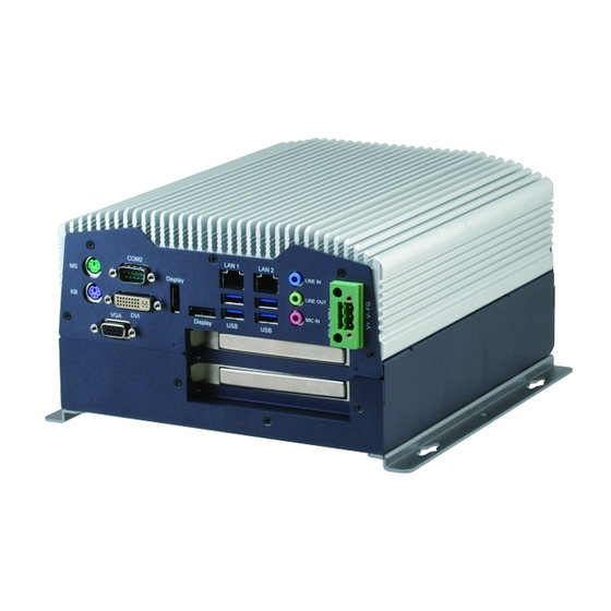
- Page 1 A E C - 6 8 7 7 AEC-6877 Fanless Embedded Controller ® Intel Core i7/ i5 ® Celeron Processor with 2 Gigabit Ethernet 2 COM, 4 USB3.0, 2 DisplayPort™ 2 PCI or 1 PCI-Express[x4] DVI-D, CFast™, SATA 3.0Gb/s AEC-6877 Manual 1st Ed. September 2012...
- Page 2 AAEON assumes no liabilities resulting from errors or omissions in this document, or from the use of the information contained herein. AAEON reserves the right to make changes in the product design without notice to its users.
- Page 3 E m b e d d e d C o n t r o l l e r A E C - 6 8 7 7 Acknowledgments Award is a trademark of Award Software International, Inc. ™ CompactFlash is a trademark of the Compact Flash Association.
- Page 4 A E C - 6 8 7 7 Packing List Before you begin operating your PC, please make sure that the following materials have been shipped: AEC-6877 Embedded Controller Phoenix Power Connector M3 x 4mm Screws ...
- Page 5 E m b e d d e d C o n t r o l l e r A E C - 6 8 7 7 Safety & Warranty 1. Read these safety instructions carefully. 2. Keep this user's manual for later reference. 3.
- Page 6 E m b e d d e d C o n t r o l l e r A E C - 6 8 7 7 The equipment does not work well, or you cannot get it to work according to the user’s manual. The equipment has been dropped and damaged.
- Page 7 E m b e d d e d C o n t r o l l e r A E C - 6 8 7 7 Below Table for China RoHS Requirements 产品中有毒有害物质或元素名称及含量 AAEON Boxer/ Industrial System 有毒有害物质或元素 部件名称 铅...
-
Page 8: Table Of Contents
E m b e d d e d C o n t r o l l e r A E C - 6 8 7 7 Contents Chapter 1 General Information 1.1 Introduction..............1-2 1.2 Features ..............1-4 1.3 Specifications ............1-5 Chapter 2 Hardware Installation 2.1 Dimension .............. - Page 9 E m b e d d e d C o n t r o l l e r A E C - 6 8 7 7 Appendix B I/O Information B.1 I/O Address Map ..........B-2 B.2 Memory Address Map ..........B-4 B.3 IRQ Mapping Chart ..........B-5 B.4 DMA Channel Assignments .........B-7 Appendix C RAID &...
-
Page 10: Chapter 1 General Information
E m b e d d e d C o n t r o l l e r A E C - 6 8 7 7 Chapter General Information Chapter 1 General Information... -
Page 11: Introduction
Stable Design for Rugged Environment The AEC-6877 is designed for rugged environments due to the following reasons; first, it can withstand tough vibration testing up to 5g rms. With the anti-vibration hard drive device option, the AEC-6877 can be used in high vibration environments. - Page 12 E m b e d d e d C o n t r o l l e r A E C - 6 8 7 7 The AEC-6877 is a standalone high performance controller designed for long-life operation and with high reliability. It can replace traditional methods and become the mainstream controller for the multimedia entertainment market.
-
Page 13: Features
E m b e d d e d C o n t r o l l e r A E C - 6 8 7 7 1.2 Features Fanless Design ® Intel Core™ i7-3610QE/ i7-2710QE/ i5-2510E/ ® Celeron -B810 Processor ... -
Page 14: Specifications
E m b e d d e d C o n t r o l l e r A E C - 6 8 7 7 1.3 Specifications ® CPU Intel Core i7-3610QE 2.3 GHz/ i7-2710QE 2.1 GHz/ i5-2510E 2.5 GHz/ ®... - Page 15 E m b e d d e d C o n t r o l l e r A E C - 6 8 7 7 KB/MS PS/2 Keyboard x 1 + Mouse x 1 Others Power input x 1 ...
- Page 16 E m b e d d e d C o n t r o l l e r A E C - 6 8 7 7 Chapter 1 General Information...
-
Page 17: Chapter 2 Hardware Installation
E m b e d d e d C o n t r o l l e r A E C - 6 8 7 7 Chapter Hardware Installation Chapter 2 Hardware Installation... -
Page 18: Dimension
E m b e d d e d C o n t r o l l e r A E C - 6 8 7 7 2.1 Dimension 2 - 2 Chapter 2 Hardware Installation... - Page 19 E m b e d d e d C o n t r o l l e r A E C - 6 8 7 7 Front side Rear side 2 - 3 Chapter 2 Hardware Installation...
-
Page 20: Com1 ~ Com2 Tx / Rx Led (Cn2)
E m b e d d e d C o n t r o l l e r A E C - 6 8 7 7 2.2 COM1 ~ COM2 TX / RX LED (CN2) Signal Signal TX_LED_COM1 -TX_LED_COM1 RX_LED_COM1 -RX_LED_COM1 COM2_RS232_PWR TX_LED_COM2... -
Page 21: Hdd Installation
A E C - 6 8 7 7 2.5 HDD Installation Step 1: Unfasten the four screws on the front and rear panels Step 2: Place the HDD to the HDD bracket and fasten to the bottom lid of AEC-6877 2 - 5 Chapter 2 Hardware Installation... - Page 22 E m b e d d e d C o n t r o l l e r A E C - 6 8 7 7 Step 3: Fasten the screws on the front and rear panels, and the brackets of AEC-6877 2 - 6 Chapter 2 Hardware Installation...
-
Page 23: Cfast™ Card Installation
E m b e d d e d C o n t r o l l e r A E C - 6 8 7 7 2.6 CFast™ Card Installation Step 1: Unfasten the screws on the front and rear panels Step 2: After installing the CFast™... -
Page 24: Pci-Express Card Installation
E m b e d d e d C o n t r o l l e r A E C - 6 8 7 7 2.7 PCI-Express Card Installation Step 1: Unfasten the screws on the front and rear panels Step 2: Install a hold-down bracket to fix the PCI or PCI-Express Card and make sure the PCI or PCI-Express Card installs properly 2 - 8... -
Page 25: Wallmount Bracket Installation
E m b e d d e d C o n t r o l l e r A E C - 6 8 7 7 2.8 Wallmount Bracket Installation Fasten the brackets with the appropriate screws. 2 - 9 Chapter 2 Hardware Installation... - Page 26 E m b e d d e d C o n t r o l l e r A E C - 6 8 7 7 Chapter BIOS Setup Chapter 3 AMI BIOS Setup 3-1...
-
Page 27: System Test And Initialization
4. The CMOS memory has lost power and the configuration information has been erased. The AEC-6877 CMOS memory has an integral lithium battery backup for data retention. However, you will need to replace the complete unit when it finally runs down. -
Page 28: Ami Bios Setup
E m b e d d e d C o n t r o l l e r A E C - 6 8 7 7 3.2 AMI BIOS Setup AMI BIOS ROM has a built-in Setup program that allows users to modify the basic system configuration. - Page 29 E m b e d d e d C o n t r o l l e r A E C - 6 8 7 7 Setup Menu Setup submenu: Main Chapter 3 AMI BIOS Setup 3-4...
- Page 30 E m b e d d e d C o n t r o l l e r A E C - 6 8 7 7 Setup submenu: Advanced Chapter 3 AMI BIOS Setup 3-5...
- Page 31 E m b e d d e d C o n t r o l l e r A E C - 6 8 7 7 ACPI Settings Options Summary : ACPI Sleep State Suspend Disabled S1 (CPU Stop Clock) S3 (Suspend to RAM) Default Select the ACPI sleep state the system will enter when the SUSPEND...
- Page 32 E m b e d d e d C o n t r o l l e r A E C - 6 8 7 7 Trusted Computing Option Summary : TPM SUPPORT Disable Default Enable Enables or Disables BIOS support for security device. O.S.
- Page 33 E m b e d d e d C o n t r o l l e r A E C - 6 8 7 7 CPU Configuration Options Summary : Hyper-threading Disabled Enabled Default Enabled for Windows XP and Linux (OS optimized for Hyper-Threading Technology) and Disabled for other OS (OS not optimized for Hyper-Threading Technology).
- Page 34 E m b e d d e d C o n t r o l l e r A E C - 6 8 7 7 SATA Configuration (IDE) Options Summary : SATA Enabled Default Controller(s) Disabled Enable or disable SATA Device. SATA Mode Default Selection...
- Page 35 E m b e d d e d C o n t r o l l e r A E C - 6 8 7 7 IDE Configuration (AHCI) Options Summary : SATA Controller(s) Disabled Enabled Default Enable or Disable SATA Port. SATA Mode Selection AHCI Selected...
- Page 36 E m b e d d e d C o n t r o l l e r A E C - 6 8 7 7 IDE Configuration (RAID) Options Summary : SATA Controller(s) Disabled Enabled Default Enable or Disable SATA Port. SATA Mode Selection AHCI RAID...
- Page 37 E m b e d d e d C o n t r o l l e r A E C - 6 8 7 7 Intel TXT(LT) Configuration Chapter 3 AMI BIOS Setup 3-12...
- Page 38 E m b e d d e d C o n t r o l l e r A E C - 6 8 7 7 PCH-FW Configuration Options Summary : MDES BIOS Status Disabled Default Code Enabled Enable/Disable MDES BIOS Status Code. Firmware Update Configure Management Engine Technology Configuration...
- Page 39 E m b e d d e d C o n t r o l l e r A E C - 6 8 7 7 Firmware Update Configuration Options Summary : Me FW Image Disabled Default Re-Flash Enabled Enable/Disable Me FW Image Re-Flash function. Chapter 3 AMI BIOS Setup 3-14...
- Page 40 E m b e d d e d C o n t r o l l e r A E C - 6 8 7 7 AMT Configuration Options Summary : Intel AMT Disabled Enabled Default Enable/Disable Intel ® Active Management Technology BIOS Extension. Note : iAMT H/W is always enabled.
- Page 41 E m b e d d e d C o n t r o l l e r A E C - 6 8 7 7 USB Configuration Options Summary : Legacy USB Support Enabled Default Disabled Auto Enable Legacy USB support. AUTO option disables legacy support if no USB devices are connected.
- Page 42 E m b e d d e d C o n t r o l l e r A E C - 6 8 7 7 Super IO Configuration Options Summary : Serial Port 0 Set Parameters of Serial Port 3 (COMA) Configuration Serial Port 1 Set Parameters of Serial Port 4 (COMB)
- Page 43 E m b e d d e d C o n t r o l l e r A E C - 6 8 7 7 Serial Port 0 Configuration Options Summary : Serial Port Disabled Enabled Default Enable or Disable Serial Port (COM) Change Settings Auto Default...
- Page 44 E m b e d d e d C o n t r o l l e r A E C - 6 8 7 7 Serial Port 1 Configuration Options Summary : Serial Port Disabled Enabled Default Enable or Disable Serial Port (COM) Change Settings Auto Default...
- Page 45 E m b e d d e d C o n t r o l l e r A E C - 6 8 7 7 H/W Monitor Chapter 3 AMI BIOS Setup 3-20...
- Page 46 E m b e d d e d C o n t r o l l e r A E C - 6 8 7 7 Setup submenu: Chipset Chapter 3 AMI BIOS Setup 3-21...
- Page 47 E m b e d d e d C o n t r o l l e r A E C - 6 8 7 7 PCH-IO Configuration Options Summary : Power Mode ATX Type Default AT Type Select power supply mode. Restore AC Power Power off Loss...
- Page 48 E m b e d d e d C o n t r o l l e r A E C - 6 8 7 7 Deep S5 Disabled Default Enabled Enabled/Disabled Deep S5. Note : When Deep S5 is enabled, Intel ® AMT and Wake On PCH LAN functions are not available In system shut down.
- Page 49 E m b e d d e d C o n t r o l l e r A E C - 6 8 7 7 System Agent (SA) Configuration Options Summary : VT-d Disabled Enabled Default Check to enable VT-d function on MCH PEG0 –...
- Page 50 E m b e d d e d C o n t r o l l e r A E C - 6 8 7 7 Graphics Configuration Options Summary : Primary Display Auto Default IGfx Select which of IGFX/PEG/PCI Graphics device should be Primary Display Or select SG for Switchable Gfx Internal Graphics Auto...
- Page 51 E m b e d d e d C o n t r o l l e r A E C - 6 8 7 7 224M 256M 288M 320M 352M 384M 416M 448M 480M 512M Select DVMT 5.0 Pre-Allocated (Fixed) Graphics Memory size used by the Internal Graphics Device.
- Page 52 E m b e d d e d C o n t r o l l e r A E C - 6 8 7 7 Display Control Options Summary : Boot Display Select VBIOS Default Default DisplayPort 1 DisplayPort 2 Select the Video Device during POST and DOS.
- Page 53 E m b e d d e d C o n t r o l l e r A E C - 6 8 7 7 Setup submenu: Boot Options Summary : Quiet Boot Disabled Enabled Default Enables or disables Quiet Boot option Launch I82579LM PXE Disabled Default...
- Page 54 E m b e d d e d C o n t r o l l e r A E C - 6 8 7 7 Hard Drives BBS Priorities Chapter 3 AMI BIOS Setup 3-29...
- Page 55 E m b e d d e d C o n t r o l l e r A E C - 6 8 7 7 Submenu: Security Change User/Supervisor Password You can install a Supervisor password, and if you install a supervisor password, you can then install a user password.
- Page 56 E m b e d d e d C o n t r o l l e r A E C - 6 8 7 7 Setup submenu: Exit Chapter 3 AMI BIOS Setup 3-31...
-
Page 57: Chapter 4 Driver Installation
E m b e d d e d C o n t r o l l e r A E C - 6 8 7 7 Chapter Driver Installation 4 -1 Chapter 4 Driver Installation... - Page 58 E m b e d d e d C o n t r o l l e r A E C - 6 8 7 7 The AEC-6877 comes with an AutoRun DVD-ROM that contains all drivers and utilities that can help you to install the driver automatically.
- Page 59 E m b e d d e d C o n t r o l l e r A E C - 6 8 7 7 4.1 Installation: Insert the AEC-6877 DVD-ROM into the DVD-ROM drive. And install the drivers from Step 1 to Step 7 in order. Step 1 – Install Chipset Driver 1.
- Page 60 E m b e d d e d C o n t r o l l e r A E C - 6 8 7 7 Step 4 –Install Audio Driver 1. Click on the Step 4- Audio folder and select the OS folder your system is 2.
-
Page 61: Appendix A Programming The Watchdog Timer
E m b e d d e d C o n t r o l l e r A E C - 6 8 7 7 Appendix Programming the Watchdog Timer Appendix A Programming the Watchdog Timer... -
Page 62: Programming
E m b e d d e d C o n t r o l l e r A E C - 6 8 7 7 A.1 Programming AEC-6877 utilizes ITE IT8728 chipset as its watchdog timer controller. Below are the procedures to complete its configuration and the AAEON intial watchdog timer program is also attached based on which you can develop customized program to fit your application. - Page 63 E m b e d d e d C o n t r o l l e r A E C - 6 8 7 7 There are three steps to complete the configuration setup: (1) Enter the MB PnP Mode; (2) Modify the data of configuration registers; (3) Exit the MB PnP Mode.
- Page 64 E m b e d d e d C o n t r o l l e r A E C - 6 8 7 7 WatchDog Timer Configuration Registers Configure Control (Index=02h) This register is write only. Its values are not sticky; that is to say, a hardware reset will automatically clear the bits, and does not require the software to clear them.
- Page 65 E m b e d d e d C o n t r o l l e r A E C - 6 8 7 7 WatchDog Timer Control Register (Index=71h, Default=00h) WatchDog Timer Configuration Register (Index=72h, Default=00h) WatchDog Timer Time-out Value Register (Index=73h, Default=00h) Appendix A Programming the Watchdog Timer...
-
Page 66: Ite8728 Watchdog Timer Initial Program
E m b e d d e d C o n t r o l l e r A E C - 6 8 7 7 A.2 ITE8728 Watchdog Timer Initial Program .MODEL SMALL .CODE Main: CALL Enter_Configuration_mode CALL Check_Chip mov cl, 7 call Set_Logic_Device ;time setting... - Page 67 E m b e d d e d C o n t r o l l e r A E C - 6 8 7 7 ; game port enable mov cl, 9 call Set_Logic_Device Initial_OK: CALL Exit_Configuration_mode MOV AH,4Ch INT 21h Enter_Configuration_Mode PROC NEAR MOV SI,WORD PTR CS:[Offset Cfg_Port]...
- Page 68 E m b e d d e d C o n t r o l l e r A E C - 6 8 7 7 Exit_Configuration_Mode ENDP Check_Chip PROC NEAR MOV AL,20h CALL Read_Configuration_Data CMP AL,87h JNE Not_Initial MOV AL,21h CALL Read_Configuration_Data CMP AL,12h JNE Not_Initial...
- Page 69 E m b e d d e d C o n t r o l l e r A E C - 6 8 7 7 MOV DX,WORD PTR CS:[Cfg_Port+06h] IN AL,DX Read_Configuration_Data ENDP Write_Configuration_Data PROC NEAR MOV DX,WORD PTR CS:[Cfg_Port+04h] OUT DX,AL XCHG AL,AH MOV DX,WORD PTR CS:[Cfg_Port+06h]...
- Page 70 E m b e d d e d C o n t r o l l e r A E C - 6 8 7 7 push ax push cx xchg al,cl mov cl,07h call Superio_Set_Reg pop cx pop ax Set_Logic_Device endp ;Select 02Eh->Index Port, 02Fh->Data Port Cfg_Port DB 087h,001h,055h,055h...
-
Page 71: Appendix B I/O Information
E m b e d d e d C o n t r o l l e r A E C - 6 8 7 7 Appendix I/O Information Appendix B I/O Information... -
Page 72: I/O Address Map
E m b e d d e d C o n t r o l l e r A E C - 6 8 7 7 B.1 I/O Address Map Appendix B I/O Information... - Page 73 E m b e d d e d C o n t r o l l e r A E C - 6 8 7 7 Appendix B I/O Information...
-
Page 74: Memory Address Map
E m b e d d e d C o n t r o l l e r A E C - 6 8 7 7 B.2 Memory Address Map Appendix B I/O Information... -
Page 75: Irq Mapping Chart
E m b e d d e d C o n t r o l l e r A E C - 6 8 7 7 B.3 IRQ Mapping Chart Appendix B I/O Information... - Page 76 E m b e d d e d C o n t r o l l e r A E C - 6 8 7 7 Appendix B I/O Information...
-
Page 77: Dma Channel Assignments
E m b e d d e d C o n t r o l l e r A E C - 6 8 7 7 B.4 DMA Channel Assignments Appendix B I/O Information... -
Page 78: Appendix C Raid & Ahci Settings
E m b e d d e d C o n t r o l l e r A E C - 6 8 7 7 A ppendix RAID & AHCI Settings Appendix C RAID & AHCI Settings... -
Page 79: Setting Raid
E m b e d d e d C o n t r o l l e r A E C - 6 8 7 7 C.1 Setting RAID OS installation to setup RAID Mode Step 1: Copy the files below from “Driver CD ->Step 6 - RAID&AHCI -> F6 Floppy - x86”... - Page 80 E m b e d d e d C o n t r o l l e r A E C - 6 8 7 7 Step 3: The setting procedures “ In BIOS Setup Menu” A: Advanced -> SATA Configuration -> SATA Mode -> RAID Mode Step 4: The setting procedures “In BIOS Setup Menu”...
- Page 81 E m b e d d e d C o n t r o l l e r A E C - 6 8 7 7 Step 5: The setting procedures “In BIOS Setup Menu” C: Boot -> Boot Option #1 -> DVD-ROM Type Step 6: The setting procedures “In BIOS Setup Menu”...
- Page 82 E m b e d d e d C o n t r o l l e r A E C - 6 8 7 7 Step 7: Press Ctrl-I to enter MAIN MENU Step 8: Choose “1.Create RAID Volume” Appendix C RAID &...
- Page 83 E m b e d d e d C o n t r o l l e r A E C - 6 8 7 7 Step 9: RAID Level -> RAID0(Stripe) Step 10: Choose “Create Volume” Appendix C RAID & AHCI Settings...
- Page 84 E m b e d d e d C o n t r o l l e r A E C - 6 8 7 7 Step 11: Choose “Y” Step 12: Choose “5. Exit” Appendix C RAID & AHCI Settings...
- Page 85 E m b e d d e d C o n t r o l l e r A E C - 6 8 7 7 Step 13: Choose “Y” Step 14: Setup OS Appendix C RAID & AHCI Settings...
- Page 86 E m b e d d e d C o n t r o l l e r A E C - 6 8 7 7 Step 15: Press “F6” Step 16: Choose “S” Appendix C RAID & AHCI Settings...
- Page 87 E m b e d d e d C o n t r o l l e r A E C - 6 8 7 7 Step 17: Choose “Intel(R) Mobile Express Chipset SATA RAID Controller” Step 18: It will show the model number you select and then press “ENTER” C-10 Appendix C RAID &...
- Page 88 E m b e d d e d C o n t r o l l e r A E C - 6 8 7 7 Step 19: Setup is starting Windows C-11 Appendix C RAID & AHCI Settings...
-
Page 89: Setting Ahci
E m b e d d e d C o n t r o l l e r A E C - 6 8 7 7 C.2 Setting AHCI OS installation to setup AHCI Mode Step 1: Copy the files below from “Driver CD -> Raid Driver -> F6 Floppy - x86”... - Page 90 E m b e d d e d C o n t r o l l e r A E C - 6 8 7 7 Step 3: The setting procedures “ In BIOS Setup Menu” A: Advanced -> SATA Configuration -> SATA Configuration -> SATA Mode ->...
- Page 91 E m b e d d e d C o n t r o l l e r A E C - 6 8 7 7 Step 5: The setting procedures “In BIOS Setup Menu” C: Save & Exit -> Save Changes and Exit Step 6: Setup OS C-14 Appendix C RAID &...
- Page 92 E m b e d d e d C o n t r o l l e r A E C - 6 8 7 7 Step 7: Press “F6” Step 8: Choose “S” C-15 Appendix C RAID & AHCI Settings...
- Page 93 E m b e d d e d C o n t r o l l e r A E C - 6 8 7 7 Step 9: Choose “Intel(R) 7 Series Chipset Family SATA AHCI Controller” tep 10: It will show the model number you select and then press “ENTER” C-16 Appendix C RAID &...
- Page 94 E m b e d d e d C o n t r o l l e r A E C - 6 8 7 7 Step 11: Setup is loading files C-17 Appendix C RAID & AHCI Settings...
Need help?
Do you have a question about the AEC-6877 and is the answer not in the manual?
Questions and answers