Table of Contents
Advertisement
Quick Links
Download this manual
See also:
User Manual
Advertisement
Table of Contents

Subscribe to Our Youtube Channel
Related Manuals for Aaeon AEC-6638


Summary of Contents for Aaeon AEC-6638
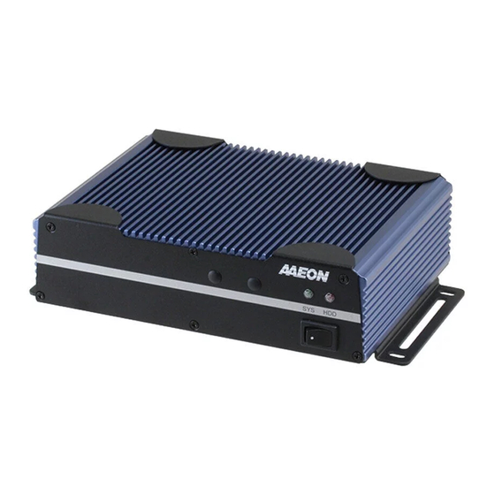
- Page 1 E m b e d d e d C o n t r o l l e r A E C - 6 6 3 8 AEC-6638 Fanless Embedded Controller ® Intel Core™ i3/i5/i7 Mobile Processor 2 Gigabit Ethernet 2 USB3.0, 2 USB2.0, 3 COM 1 Mini Card AEC-6638 Manual 2 March 9, 2015...
- Page 2 AAEON assumes no liabilities resulting from errors or omissions in this document, or from the use of the information contained herein. AAEON reserves the right to make changes in the product design without notice to its users.
- Page 3 E m b e d d e d C o n t r o l l e r A E C - 6 6 3 8 Acknowledgments All other products’ name or trademarks are properties of their respective owners. • AMI is a trademark of American Megatrends Inc.
- Page 4 E m b e d d e d C o n t r o l l e r A E C - 6 6 3 8 Packing List Before you begin operating the product, please make sure that the following materials are enclosed: AEC-6638 Embedded Controller Wallmount Brackets Screw Package ...
- Page 5 E m b e d d e d C o n t r o l l e r A E C - 6 6 3 8 Safety & Warranty 1. Read these safety instructions carefully. 2. Keep this user's manual for later reference. 3.
- Page 6 E m b e d d e d C o n t r o l l e r A E C - 6 6 3 8 The equipment does not work well, or you cannot get it to work according to the user’s manual. The equipment has been dropped and damaged.
- Page 7 E m b e d d e d C o n t r o l l e r A E C - 6 6 3 8 China RoHS Requirements 产品中有毒有害物质或元素名称及含量 AAEON Boxer/ Industrial System 有毒有害物质或元素 部件名称 铅 汞 镉 六价铬...
-
Page 8: Table Of Contents
1.1 Introduction ..............1-2 1.2 Features ..............1-3 1.3 Specifications ............1-4 Chapter 2 Hardware Installation 2.1 Dimensions & Connectors of AEC-6638 ....2-2 2.2 List of Jumpers ............2-3 2.3 List of Connectors ............. 2-6 2.4 Setting Jumpers ............2-7 2.5 Mini-Card with mSATA/PCIe Selection (JP1) ... - Page 9 E m b e d d e d C o n t r o l l e r A E C - 6 6 3 8 Chapter 4 Driver Installation 4.1 Installation ..............4-3 Appendix A Programming The Watchdog Timer A.1 Programming ............
-
Page 10: Chapter 1 General Information
E m b e d d e d C o n t r o l l e r A E C - 6 6 3 8 Chapter General Information 1- 1 Chapter 1 General Information... -
Page 11: Introduction
It can replace traditional methods and become the mainstream controller for the Industrial Automation market. If you are looking for a multifunctional embedded controller, the AEC-6638 is definitely your best choice to fit into your vital applications. 1- 2... -
Page 12: Features
E m b e d d e d C o n t r o l l e r A E C - 6 6 3 8 1.2 Features ® Intel Generation Core™ i3-4100E/i5-4400E/i7-4700EQ Processor COM x 3, USB2.0 x 2, USB3.0 x 2 ... -
Page 13: Specifications
E m b e d d e d C o n t r o l l e r A E C - 6 6 3 8 1.3 Specifications ® Intel Core™ i3-4100E 2.4GHz processor ® Intel Core™ i5-4400E 2.7GHz processor ®... - Page 14 E m b e d d e d C o n t r o l l e r A E C - 6 6 3 8 DVI-D x 1 HDMI x 1 RJ-45 x 2 for 10/100/1000 base-T MINI card x 1 for optional wireless Expansion module 9~30V DC with 3-pin terminal block...
-
Page 15: Chapter 2 Hardware Installation
E m b e d d e d C o n t r o l l e r A E C - 6 6 3 8 Chapter Hardware Installation Chapter 2 Hardware Installation... -
Page 16: Dimensions & Connectors Of Aec-6638
E m b e d d e d C o n t r o l l e r A E C - 6 6 3 8 2.1 Dimensions & Connectors of AEC-6638 A1M/A2M/A3M Version 2 - 2 Chapter 2 Hardware Installation... -
Page 17: List Of Jumpers
E m b e d d e d C o n t r o l l e r A E C - 6 6 3 8 Connectors on the front panel Connectors on the rear panel 2.2 List of Jumpers The board has a number of jumpers that allow you to configure your system to suit your application. -
Page 18: List Of Connectors
E m b e d d e d C o n t r o l l e r A E C - 6 6 3 8 LVDS Port 1 Backlight Inverter Voltage Selection LVDS Port 1 Backlight Lightness Control Mode Selection LVDS Port 1 Operating Voltage Selection LVDS Port 2 Operating Voltage Selection LVDS Port 2 Backlight Inverter Voltage Selection... - Page 19 E m b e d d e d C o n t r o l l e r A E C - 6 6 3 8 CN12 USB 2.0 Port 3 CN13 USB 2.0 Port 4 CN14 LVDS Port 1 CN15 LVDS Port 2 CN16...
- Page 20 E m b e d d e d C o n t r o l l e r A E C - 6 6 3 8 CN36 UIM Socket PCIE1 Mini-Card CFD1 C-FAST DIMM1 DDR3L SODIMM 2 - 6 Chapter 2 Hardware Installation...
-
Page 21: Setting Jumpers
E m b e d d e d C o n t r o l l e r A E C - 6 6 3 8 2.4 Setting Jumpers You configure your card to match the needs of your application by setting jumpers. -
Page 22: Mini-Card With Msata/Pcie Selection (Jp1)
E m b e d d e d C o n t r o l l e r A E C - 6 6 3 8 2.5 Mini-Card with mSATA / PCIe Selection (JP1) mSATA PCIe (Default) Function mSATA PCIe (Default) 2.6 AT/ATX Power Supply Mode Selection (JP9) Function ATX Mode (Default) -
Page 23: Com Port 3 Connector (Cn21)
E m b e d d e d C o n t r o l l e r A E C - 6 6 3 8 Ring (Default) 2.9 COM Port 3 Connector (CN21) Signal Signal DCDC DTRC Ground DSRC RTSC CTSC 2.10 COM Port 4 Connector (CN22) - Page 24 E m b e d d e d C o n t r o l l e r A E C - 6 6 3 8 RS-232 Mode Signal Signal DCDB DTRB Ground DSRB RTSB CTSB RIB/ +5V/ (+12V) RS-422 Mode Signal Signal TXD-...
-
Page 25: Cfast™ Card Installation
E m b e d d e d C o n t r o l l e r A E C - 6 6 3 8 2.12 CFast™ Card Installation Step 1: Unfasten the screws on the AEC-6638 Step 2: Unfasten the screws on the brackets 2 - 11... - Page 26 E m b e d d e d C o n t r o l l e r A E C - 6 6 3 8 Step 3: Unfasten the screws on the bottom cover Step 4: Install the CFast™ Card to the CFast™ slot and adhere the thermal pad onto the CFast™...
- Page 27 E m b e d d e d C o n t r o l l e r A E C - 6 6 3 8 Step 5: Fasten the screws of the CFast™ bracket Step 6: Close the bottom cover of the AEC-6638 and fasten the screws to complete installation 2 - 13...
-
Page 28: Hard Disk Drive (Hdd) Installation
E m b e d d e d C o n t r o l l e r A E C - 6 6 3 8 2.13 Hard Disk Drive (HDD) Installation Step 1: Unfasten the screws on the AEC-6638 Step 2: Unfasten the screws on the brackets 2 - 14... - Page 29 E m b e d d e d C o n t r o l l e r A E C - 6 6 3 8 Step 3: Unfasten the screws on the bottom cover Step 4: Get the HDD and HDD Bracket ready. Fasten the screws to fix the HDD and HDD bracket 2 - 15 Chapter 2 Hardware Installation...
- Page 30 E m b e d d e d C o n t r o l l e r A E C - 6 6 3 8 Step 5: Connect the SATA cable to the HDD Step 6: Close the bottom cover of the AEC-6638 and fasten the screws to complete installation 2 - 16...
-
Page 31: Memory Card Installation
E m b e d d e d C o n t r o l l e r A E C - 6 6 3 8 2.14 Memory Card Installation Step 1: Unfasten the screws on the AEC-6638 Step 2: Unfasten the screws on the brackets 2 - 17... - Page 32 E m b e d d e d C o n t r o l l e r A E C - 6 6 3 8 Step 3: Unfasten the screws on the bottom cover Step 4: Unfasten the screws of the bracket of Memory Card 2 - 18 Chapter 2 Hardware Installation...
- Page 33 E m b e d d e d C o n t r o l l e r A E C - 6 6 3 8 Step 5: Adhere the Thermal pads onto the top and bottom of the Memory Card, and then insert the RAM at 30-degree angle to the memory slot and press Step 6: Fasten the screws on the bracket of the Memory Card to complete...
-
Page 34: Wallmount Kit Installation
A E C - 6 6 3 8 2.15 Wallmount Kit Installation Get the brackets ready and fasten the appropriate screws on each bracket. Attach and secure the two brackets onto the bottom lid of AEC-6638 to complete installation. 2 - 20... - Page 35 E m b e d d e d C o n t r o l l e r A E C - 6 6 3 8 Chapter BIOS Setup Chapter 3 AMI BIOS Setup 3-1...
-
Page 36: System Test And Initialization
3. The CMOS memory has lost power and the configuration information has been erased. The AEC-6638 CMOS memory has an integral lithium battery backup for data retention. However, you will need to replace the complete unit when it finally runs down. -
Page 37: Ami Bios Setup
E m b e d d e d C o n t r o l l e r A E C - 6 6 3 8 3.2 AMI BIOS Setup AMI BIOS ROM has a built-in Setup program that allows users to modify the basic system configuration. - Page 38 E m b e d d e d C o n t r o l l e r A E C - 6 6 3 8 Setup Menu Setup submenu: Main Options summary: (default setting) System Date Day MM:DD:YYYY Change the month, year and century. The ‘Day’ is changed automatically. System Time HH : MM : SS Change the clock of the system.
- Page 39 E m b e d d e d C o n t r o l l e r A E C - 6 6 3 8 Setup submenu: Advanced Options summary: (default setting) ACPI Settings System ACPI Parameters S5 RTC Wake Settings Enable system to wake from S5 using RTC alarm.
- Page 40 E m b e d d e d C o n t r o l l e r A E C - 6 6 3 8 AMT Configuration AMT Configuration Parameters USB Configuration USB Configuration Parameters Super IO Configuration Super IO Configuration Parameters H/W Monitor Monitor hardware status ACPI Settings...
- Page 41 E m b e d d e d C o n t r o l l e r A E C - 6 6 3 8 S3 only(Suspend to RAM) Select the ACPI state used for System Suspend Disabled Wake on Ring Enabled Enable/Disable Wake on Ring function RTC Wake Settings...
- Page 42 E m b e d d e d C o n t r o l l e r A E C - 6 6 3 8 Select 0 for daily system wake up Wake up hour 0-23 Wake up minute 0-59 Wake up second 0-59...
- Page 43 E m b e d d e d C o n t r o l l e r A E C - 6 6 3 8 Trusted Computing Options summary: (default setting) Security Device Support Disabled Enabled En/Disable TPM support. TPM State Disabled Enabled...
- Page 44 E m b e d d e d C o n t r o l l e r A E C - 6 6 3 8 TPM Clear Select one-time TPM operation. Item value returns to ‘None’ after next POST. CPU Configuration Options summary: (default setting) Hyper-Threading...
- Page 45 E m b e d d e d C o n t r o l l e r A E C - 6 6 3 8 Technology Enabled En/Disable Intel VT-x function EIST Disabled Enabled En/Disable Intel SpeedStep Turbo Mode Disabled Enabled En/Disable Turbo mode...
- Page 46 E m b e d d e d C o n t r o l l e r A E C - 6 6 3 8 Options summary: (default setting) SATA Controller(s) Disabled Enabled En/Disable SATA controller SATA Mode Selection AHCI RAID Configure SATA controller operating as IDE/AHCI/RAID mode.
- Page 47 E m b e d d e d C o n t r o l l e r A E C - 6 6 3 8 AMT Configuration Options summary: (default setting) Intel AMT Enabled Disabled En/Disable Intel® Active Management Technology BIOS Extension. Note: iAMT H/W is always enabled.
- Page 48 E m b e d d e d C o n t r o l l e r A E C - 6 6 3 8 USB Configuration Options summary: (default setting) Legacy USB Support Enabled Disabled Auto Enables BIOS Support for Legacy USB Support. When enabled, USB can be functional in legacy environment like DOS.
- Page 49 E m b e d d e d C o n t r o l l e r A E C - 6 6 3 8 Enables BIOS Support for USB3.0 (XHCI). When disabled, PCH USB3.0 controller will also be disabled. Device Name Auto (Emulation Type)
- Page 50 E m b e d d e d C o n t r o l l e r A E C - 6 6 3 8 Serial Port 2/3/4 Configuration Set Parameters of Serial Port 2/3/4 Serial Port X Configuration Options summary: (default setting) Serial Port Disabled...
- Page 51 E m b e d d e d C o n t r o l l e r A E C - 6 6 3 8 IO=3E8h; IRQ=3,4,5,7,10,11,12; IO=2E8h; IRQ=3,4,5,7,10,11,12; Select a resource setting for Super IO device. Device Type RS232 RS422 RS485...
- Page 52 E m b e d d e d C o n t r o l l e r A E C - 6 6 3 8 Setup submenu: Chipset Options summary: (default setting) PCH-IO Configuration South Bridge Parameters System Agent (SA) Configuration SA Parameters Chapter 3 AMI BIOS Setup 3-18...
- Page 53 E m b e d d e d C o n t r o l l e r A E C - 6 6 3 8 PCH-IO Configuration Options summary: (default setting) Power Mode ATX Type AT Type Enable or disable ‘It is now safe to turn off your computer.’ string PCI Express Configuration PCI Express Configuration settings...
- Page 54 E m b e d d e d C o n t r o l l e r A E C - 6 6 3 8 Disabled En/Disabled integrated LAN to wake the system. (The Wake on LAN cannot be disabled if ME is on at Sx state.
- Page 55 E m b e d d e d C o n t r o l l e r A E C - 6 6 3 8 CPU SA Audio Device Enabled (B0:D3:F0) Disabled En/Disable CPU SA Audio Device Graphics Configuration Config Graphics Settings Graphics Configuration Options summary: (default setting)
- Page 56 E m b e d d e d C o n t r o l l e r A E C - 6 6 3 8 PCIE Select graphic adapters to boot Internal Graphics Auto Disabled Enabled En/Disabled internal graphics device DVMT Pre-Allocated 32MB 64MB~1024MB...
- Page 57 E m b e d d e d C o n t r o l l e r A E C - 6 6 3 8 LCD Control Options summary: (default setting) Primary IGFX Boot Display VBIOS Defat HDMI Select Primary IGFX boot display device Chapter 3 AMI BIOS Setup 3-23...
- Page 58 E m b e d d e d C o n t r o l l e r A E C - 6 6 3 8 Setup submenu: Boot Options summary: (default setting) Quiet Boot Disabled Enabled En/Disable showing boot logo. Launch PXE OpROM Disabled policy...
- Page 59 E m b e d d e d C o n t r o l l e r A E C - 6 6 3 8 BBS Priorities Options summary: (default setting) Boot Option #x Disabled Device name Sets the system boot order Chapter 3 AMI BIOS Setup 3-25...
- Page 60 E m b e d d e d C o n t r o l l e r A E C - 6 6 3 8 Setup submenu: Security Options summary: (default setting) Administrator Password/ Not set User Password Chapter 3 AMI BIOS Setup 3-26...
- Page 61 E m b e d d e d C o n t r o l l e r A E C - 6 6 3 8 You can install a Supervisor password, and if you install a supervisor password, you can then install a user password.
- Page 62 E m b e d d e d C o n t r o l l e r A E C - 6 6 3 8 Setup submenu: Exit Options summary: (default setting) Save Changes and Exit Exit system setup after saving the changes Discard Changes and Exit Exit system setup without saving any changes Save Changes and Reset...
- Page 63 E m b e d d e d C o n t r o l l e r A E C - 6 6 3 8 Discard Changes done so far to any of the setup options Reset system setup without saving any changes Restore Defaults Restore/Load Default values...
-
Page 64: Chapter 4 Driver Installation
E m b e d d e d C o n t r o l l e r A E C - 6 6 3 8 Chapter D river Installation 4 -1 Chapter 4 Driver Installation... - Page 65 A E C - 6 6 3 8 4.1 Installation The AEC-6638 comes with a driver disk that contains all drivers and utilities that can help you setup your product. Insert the disk and the installation guide will start automatically. If it doesn’t, please follow the sequence below to install the drivers.
- Page 66 E m b e d d e d C o n t r o l l e r A E C - 6 6 3 8 4.1 Installation Insert the AEC-6638 driver disk into the disk drive. And install the drivers from Step 1 to Step 9 in order. Step 1 – Install Chipset Driver 1.
- Page 67 E m b e d d e d C o n t r o l l e r A E C - 6 6 3 8 2. Open the.exe file in the folder 3. Follow the instructions 4. Drivers will be installed automatically Step 5 –...
- Page 68 E m b e d d e d C o n t r o l l e r A E C - 6 6 3 8 Step 9 – Install Serial Port Driver (Optional) 1. Open the Step9 - Serial Port Driver (Optional) folder and select your OS folder 2.
-
Page 69: Appendix A Programming The Watchdog Timer
S u b C o m p a c t B o a r d A E C - 6 6 3 8 Appendix Programming the Watchdog Timer Appendix A Programming the Watchdog Timer A-1... -
Page 70: Programming
S u b C o m p a c t B o a r d A E C - 6 6 3 8 A.1 Programming AEC-6638 utilizes FINTEK 81866 chipset as its watchdog timer controller. Below are the procedures to complete its configuration and the AAEON initial watchdog timer program is also attached based on which you can develop customized program to fit your application. - Page 71 S u b C o m p a c t B o a r d A E C - 6 6 3 8 There are three steps to complete the configuration setup: (1) Enter the MB PnP Mode; (2) Modify the data of configuration registers; (3) Exit the MB PnP Mode.
- Page 72 S u b C o m p a c t B o a r d A E C - 6 6 3 8 Watch Dog Timer 1, 2, 3 Control Register (Index=F5h,F6h,FAh Default=00h) Appendix A Programming the Watchdog Timer A-4...
-
Page 73: F81866 Watchdog Timer Initial Program
S u b C o m p a c t B o a r d A E C - 6 6 3 8 A.2 F81866 Watchdog Timer Initial Program Main aaeonSuperIOOpen(); aaeonWdtSetCountMode(BOOL bMinute); // Set wdt count mode aaeonWdtSetTimeoutCount(BYTE tTimeout); // Set wdt timer aaeonWdtSetEnable(BOOL bEnable);... - Page 74 S u b C o m p a c t B o a r d A E C - 6 6 3 8 Void aaeonWdtSetTimeoutCount(BYTE tTimeout){ f81866SetLdn(0x07); f81866WriteByte(F81866_WDT_TIME_REG, tTimeout); Void aaeonWdtSetEnable(BOOL bEnable){ f81866SetLdn(0x07); if(bEnable){ f81866WriteByte(0x30, 0x01); WDT_BASE_ADDR = (f81866ReadByte(F81866_WDT_BASEADDR_REG_MSB) << 8) | f81866ReadByte(F81866_WDT_BASEADDR_REG_LSB);...
- Page 75 S u b C o m p a c t B o a r d A E C - 6 6 3 8 Void aaeonSuperIOClose(){ aaeonioWritePortByte(F81866_INDEX, 0xaa); Appendix A Programming the Watchdog Timer A-7...
-
Page 76: Appendix B I/O Information
E m b e d d e d C o n t r o l l e r A E C - 6 6 3 8 Appendix I/O Information Appendix B I/O Information... -
Page 77: I/O Address Map
E m b e d d e d C o n t r o l l e r A E C - 6 6 3 8 B.1 I/O Address Map Appendix B I/O Information... - Page 78 E m b e d d e d C o n t r o l l e r A E C - 6 6 3 8 Appendix B I/O Information...
-
Page 79: Memory Address Map
E m b e d d e d C o n t r o l l e r A E C - 6 6 3 8 B.2 Memory Address Map Appendix B I/O Information... -
Page 80: Irq Mapping Chart
E m b e d d e d C o n t r o l l e r A E C - 6 6 3 8 B.3 IRQ Mapping Chart Appendix B I/O Information... - Page 81 E m b e d d e d C o n t r o l l e r A E C - 6 6 3 8 Appendix B I/O Information...
-
Page 82: Dma Channel Assignments
E m b e d d e d C o n t r o l l e r A E C - 6 6 3 8 B.4 DMA Channel Assignments Appendix B I/O Information...
Need help?
Do you have a question about the AEC-6638 and is the answer not in the manual?
Questions and answers