Table of Contents
Advertisement
Quick Links
Advertisement
Table of Contents

Subscribe to Our Youtube Channel
Related Manuals for Aaeon AEC-6876


Summary of Contents for Aaeon AEC-6876
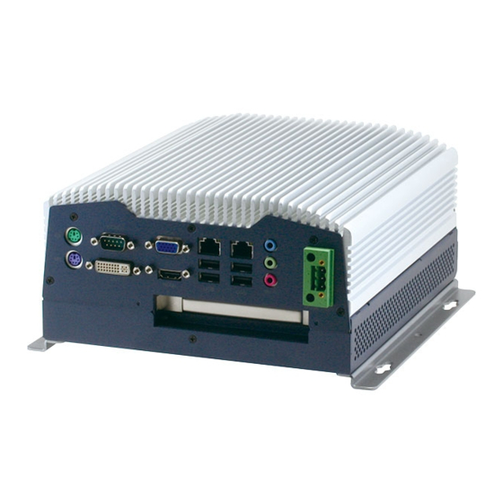
- Page 1 A E C - 6 8 7 6 AEC-6876 Fanless Embedded Controller ® Intel Core i5-2510E/ ® Celeron -B810 Processor with 2 Gigabit Ethernet 4 COM, 4 USB, 1 PCI-Express[x4] DVI, HDMI, VGA AEC-6876 Manual 2nd Ed. March 18, 2014...
- Page 2 AAEON assumes no liabilities resulting from errors or omissions in this document, or from the use of the information contained herein. AAEON reserves the right to make changes in the product design without notice to its users.
- Page 3 E m b e d d e d C o n t r o l l e r A E C - 6 8 7 6 Acknowledgments Award is a trademark of Award Software International, Inc. ™ CompactFlash is a trademark of the Compact Flash Association.
- Page 4 A E C - 6 8 7 6 Packing List Before you begin operating your PC, please make sure that the following materials have been shipped: AEC-6876 Embedded Controller Phoenix Power Connector M3 x 4mm Screws ...
- Page 5 E m b e d d e d C o n t r o l l e r A E C - 6 8 7 6 Safety & Warranty 1. Read these safety instructions carefully. 2. Keep this user's manual for later reference. 3.
- Page 6 E m b e d d e d C o n t r o l l e r A E C - 6 8 7 6 The equipment does not work well, or you cannot get it to work according to the user’s manual. The equipment has been dropped and damaged.
- Page 7 E m b e d d e d C o n t r o l l e r A E C - 6 8 7 6 Below Table for China RoHS Requirements 产品中有毒有害物质或元素名称及含量 AAEON Boxer/ Industrial System 有毒有害物质或元素 部件名称 铅...
-
Page 8: Table Of Contents
E m b e d d e d C o n t r o l l e r A E C - 6 8 7 6 Contents Chapter 1 General Information 1.1 Introduction ..............1-2 1.2 Features ..............1-4 1.3 Specifications ............1-5 Chapter 2 Hardware Installation 2.1 Dimension .............. - Page 9 E m b e d d e d C o n t r o l l e r A E C - 6 8 7 6 A.2 ITE8728 Watchdog Timer Initial Program....A-6 Appendix B I/O Information B.1 I/O Address Map ..........B-2 B.2 Memory Address Map ..........
-
Page 10: Chapter 1 General Information
E m b e d d e d C o n t r o l l e r A E C - 6 8 7 6 Chapter General Information Chapter 1 General Information... -
Page 11: Introduction
Being a control center, the AEC-6876 is suitable for public multimedia entertainment services. Equipped with a high efficiency heat conduction mechanism. The AEC-6876 is compact in size but has attractive and flexible extension capabilities such as 4 USB2.0 ports, VGA, Audio, 4 COM ports, and PCI-Express slot. - Page 12 A E C - 6 8 7 6 5 g rms. With the anti-vibration hard drive device option, the AEC-6876 can be used in high vibration environments. In addition, the AEC-6876 offers low power consumption system that while operating in ambient temperatures ranging from -10° to 55°C.
-
Page 13: Features
E m b e d d e d C o n t r o l l e r A E C - 6 8 7 6 1.2 Features Fanless Design ® ® Intel Core™ i5-2510E/ Celeron -B810 Processor ... -
Page 14: Specifications
E m b e d d e d C o n t r o l l e r A E C - 6 8 7 6 1.3 Specifications ® CPU Intel Core i5-2510E 2.5 GHz/ ® Celeron -B810 1.6 GHz Processor ®... - Page 15 E m b e d d e d C o n t r o l l e r A E C - 6 8 7 6 Mini Card Indicator Front Power LED x 1, HDD active LED x 1 ...
- Page 16 E m b e d d e d C o n t r o l l e r A E C - 6 8 7 6 Chapter 1 General Information...
-
Page 17: Chapter 2 Hardware Installation
E m b e d d e d C o n t r o l l e r A E C - 6 8 7 6 Chapter Hardware Installation Chapter 2 Hardware Installation... -
Page 18: Dimension
E m b e d d e d C o n t r o l l e r A E C - 6 8 7 6 2.1 Dimension A1/A2 version 2 - 2 Chapter 2 Hardware Installation... - Page 19 E m b e d d e d C o n t r o l l e r A E C - 6 8 7 6 A1M/A2M Version 2 - 3 Chapter 2 Hardware Installation...
-
Page 20: Rs-232/422/485 Pin Header (Com2)
E m b e d d e d C o n t r o l l e r A E C - 6 8 7 6 2.2 RS-232 Box Header (COM1) P in S ignal S ignal 2 5 B 2.3 RS-232/422/485 Pin Header (COM2) RS-232 Mode P in... -
Page 21: Rs-232 Box Header (Com3~Com6)
E m b e d d e d C o n t r o l l e r A E C - 6 8 7 6 RS-485 Mode Signal Signal Ground 2.4 RS-232 Box Header (COM3~COM6) P in S ignal S ignal 2 5 B 2.5 USB Box Header (USB3~USB4) -
Page 22: Hdd Installation
E m b e d d e d C o n t r o l l e r A E C - 6 8 7 6 2.6 HDD Installation Step 1: Unfasten the two screws on the front and rear panels 2 - 6 Chapter 2 Hardware Installation... - Page 23 A E C - 6 8 7 6 Step 2: Unfasten the six screws on the bottom lid Step 3: Place the HDD to the HDD bracket and fasten to the bottom lid of AEC-6876 2 - 7 Chapter 2 Hardware Installation...
- Page 24 E m b e d d e d C o n t r o l l e r A E C - 6 8 7 6 Step 4: Fasten the screws on the front and rear panels, and the brackets of AEC-6876 2 - 8 Chapter 2 Hardware Installation...
-
Page 25: Cfast™ Card Installation
2.7 CFast™ Card Installation Step 1: Unfasten the screws on the front and rear panels, and the brackets of AEC-6876 Step 2: After installing the CFast™ Card to the CFast™ Slot, you have to use the cover to fix the CFast™ Card by fastening the two screws CFast™... -
Page 26: Pci-Express Card Installation
E m b e d d e d C o n t r o l l e r A E C - 6 8 7 6 2.8 PCI-Express Card Installation Step 1: Unfasten the two screws on the front and rear panels 2 - 10 Chapter 2 Hardware Installation... - Page 27 E m b e d d e d C o n t r o l l e r A E C - 6 8 7 6 Step 2: Unfasten the six screws on the bottom lid Step 3: Install a hold-down bracket to fix the PCI or PCI-Express Card and make sure the PCI or PCI-Express Card installs properly 2 - 11 Chapter 2 Hardware Installation...
-
Page 28: Wallmount Bracket Installation
E m b e d d e d C o n t r o l l e r A E C - 6 8 7 6 2.9 Wallmount Bracket Installation Fasten the brackets with the appropriate screws. 2 - 12 Chapter 2 Hardware Installation... -
Page 29: Chapter 3 Ami Bios Setup
E m b e d d e d C o n t r o l l e r A E C - 6 8 7 6 Chapter BIOS Setup Chapter 3 AMI BIOS Setup 3-1... -
Page 30: System Test And Initialization
3. The CMOS memory has lost power and the configuration information has been erased. The AEC-6876 CMOS memory has an integral lithium battery backup for data retention. However, you will need to replace the complete unit when it finally runs down. -
Page 31: Ami Bios Setup
E m b e d d e d C o n t r o l l e r A E C - 6 8 7 6 3.2 AMI BIOS Setup AMI BIOS ROM has a built-in Setup program that allows users to modify the basic system configuration. -
Page 32: Chapter 4 Driver Installation
E m b e d d e d C o n t r o l l e r A E C - 6 8 7 6 Chapter Driver Installation 4 -1 Chapter 4 Driver Installation... - Page 33 E m b e d d e d C o n t r o l l e r A E C - 6 8 7 6 The AEC-6876 comes with an AutoRun DVD-ROM that contains all drivers and utilities that can help you to install the driver automatically.
- Page 34 E m b e d d e d C o n t r o l l e r A E C - 6 8 7 6 4.1 Installation: Insert the AEC-6876 DVD-ROM into the DVD-ROM drive. And install the drivers from Step 1 to Step 8 in order. Step 1 – Install Chipset Driver 1.
- Page 35 E m b e d d e d C o n t r o l l e r A E C - 6 8 7 6 ® Note 2: If the OS is Windows XP, you have to install the driver of dotNet Framework first.
- Page 36 E m b e d d e d C o n t r o l l e r A E C - 6 8 7 6 Step 6 – Install RAID & AHCI Driver Please refer to the Appendix C RAID & AHCI Settings Step 7 –...
- Page 37 E m b e d d e d C o n t r o l l e r A E C - 6 8 7 6 2. Change User Account Control Settings to [Never notify] 3. Reboot and Administrator login. 4 -6 Chapter 4 Driver Installation...
- Page 38 E m b e d d e d C o n t r o l l e r A E C - 6 8 7 6 4. To run patch.bat with [Run as administrator]. 4 -7 Chapter 4 Driver Installation...
-
Page 39: Appendix A Programming The Watchdog Timer
E m b e d d e d C o n t r o l l e r A E C - 6 8 7 6 Appendix Programming the Watchdog Timer Appendix A Programming the Watchdog Timer... -
Page 40: Programming
E m b e d d e d C o n t r o l l e r A E C - 6 8 7 6 A.1 Programming AEC-6876 utilizes ITE IT8728 chipset as its watchdog timer controller. Below are the procedures to complete its configuration and the AAEON intial watchdog timer program is also attached based on which you can develop customized program to fit your application. - Page 41 E m b e d d e d C o n t r o l l e r A E C - 6 8 7 6 There are three steps to complete the configuration setup: (1) Enter the MB PnP Mode; (2) Modify the data of configuration registers; (3) Exit the MB PnP Mode.
- Page 42 E m b e d d e d C o n t r o l l e r A E C - 6 8 7 6 WatchDog Timer Configuration Registers Configure Control (Index=02h) This register is write only. Its values are not sticky; that is to say, a hardware reset will automatically clear the bits, and does not require the software to clear them.
- Page 43 E m b e d d e d C o n t r o l l e r A E C - 6 8 7 6 WatchDog Timer Control Register (Index=71h, Default=00h) WatchDog Timer Configuration Register (Index=72h, Default=00h) WatchDog Timer Time-out Value Register (Index=73h, Default=00h) Appendix A Programming the Watchdog Timer...
-
Page 44: Ite8728 Watchdog Timer Initial Program
E m b e d d e d C o n t r o l l e r A E C - 6 8 7 6 A.2 ITE8728 Watchdog Timer Initial Program .MODEL SMALL .CODE Main: CALL Enter_Configuration_mode CALL Check_Chip mov cl, 7 call Set_Logic_Device ;time setting... - Page 45 E m b e d d e d C o n t r o l l e r A E C - 6 8 7 6 ; game port enable mov cl, 9 call Set_Logic_Device Initial_OK: CALL Exit_Configuration_mode MOV AH,4Ch INT 21h Enter_Configuration_Mode PROC NEAR MOV SI,WORD PTR CS:[Offset Cfg_Port]...
- Page 46 E m b e d d e d C o n t r o l l e r A E C - 6 8 7 6 Exit_Configuration_Mode ENDP Check_Chip PROC NEAR MOV AL,20h CALL Read_Configuration_Data CMP AL,87h JNE Not_Initial MOV AL,21h CALL Read_Configuration_Data CMP AL,12h JNE Not_Initial...
- Page 47 E m b e d d e d C o n t r o l l e r A E C - 6 8 7 6 MOV DX,WORD PTR CS:[Cfg_Port+06h] IN AL,DX Read_Configuration_Data ENDP Write_Configuration_Data PROC NEAR MOV DX,WORD PTR CS:[Cfg_Port+04h] OUT DX,AL XCHG AL,AH MOV DX,WORD PTR CS:[Cfg_Port+06h]...
- Page 48 E m b e d d e d C o n t r o l l e r A E C - 6 8 7 6 push ax push cx xchg al,cl mov cl,07h call Superio_Set_Reg pop cx pop ax Set_Logic_Device endp ;Select 02Eh->Index Port, 02Fh->Data Port Cfg_Port DB 087h,001h,055h,055h...
-
Page 49: Appendix B I/O Information
E m b e d d e d C o n t r o l l e r A E C - 6 8 7 6 Appendix I/O Information Appendix B I/O Information... -
Page 50: I/O Address Map
E m b e d d e d C o n t r o l l e r A E C - 6 8 7 6 B.1 I/O Address Map Appendix B I/O Information... - Page 51 E m b e d d e d C o n t r o l l e r A E C - 6 8 7 6 Appendix B I/O Information...
-
Page 52: Memory Address Map
E m b e d d e d C o n t r o l l e r A E C - 6 8 7 6 B.2 Memory Address Map Appendix B I/O Information... -
Page 53: Irq Mapping Chart
E m b e d d e d C o n t r o l l e r A E C - 6 8 7 6 B.3 IRQ Mapping Chart B.4 DMA Channel Assignments Appendix B I/O Information... - Page 54 E m b e d d e d C o n t r o l l e r A E C - 6 8 7 6 A ppendix RAID & AHCI Settings Appendix C RAID & AHCI Settings...
-
Page 55: Setting Raid
E m b e d d e d C o n t r o l l e r A E C - 6 8 7 6 C.1 Setting RAID OS installation to setup RAID Mode Step 1: Copy the files below from “Driver CD -> Raid Driver -> F6 Floppy - x86”... - Page 56 E m b e d d e d C o n t r o l l e r A E C - 6 8 7 6 Step 3: The setting procedures “ In BIOS Setup Menu” A: Advanced -> SATA Configuration -> SATA Mode -> RAID Mode Step 4: The setting procedures “In BIOS Setup Menu”...
- Page 57 E m b e d d e d C o n t r o l l e r A E C - 6 8 7 6 Step 5: The setting procedures “In BIOS Setup Menu” C: Boot -> Boot Option #1 -> DVD-ROM Type Step 6: The setting procedures “In BIOS Setup Menu”...
- Page 58 E m b e d d e d C o n t r o l l e r A E C - 6 8 7 6 Step 7: Press Ctrl-I to enter MAIN MENU Step 8: Choose “1.Create RAID Volume” Appendix C RAID &...
- Page 59 E m b e d d e d C o n t r o l l e r A E C - 6 8 7 6 Step 9: RAID Level -> RAID0(Stripe) Step 10: Choose “Create Volume” Appendix C RAID & AHCI Settings...
- Page 60 E m b e d d e d C o n t r o l l e r A E C - 6 8 7 6 Step 11: Choose “Y” Step 12: Choose “5. Exit” Appendix C RAID & AHCI Settings...
- Page 61 E m b e d d e d C o n t r o l l e r A E C - 6 8 7 6 Step 13: Choose “Y” Step 14: Setup OS Appendix C RAID & AHCI Settings...
- Page 62 E m b e d d e d C o n t r o l l e r A E C - 6 8 7 6 Step 15: Press “F6” Step 16: Choose “S” Appendix C RAID & AHCI Settings...
- Page 63 E m b e d d e d C o n t r o l l e r A E C - 6 8 7 6 Step 17: Choose “Intel(R) ICH8M-E/ICH9M-E/5 Series SATA RAID Controller” Step 18: It will show the model number you select and then press “ENTER” C-10 Appendix C RAID &...
- Page 64 E m b e d d e d C o n t r o l l e r A E C - 6 8 7 6 Step 19: Setup is starting Windows C-11 Appendix C RAID & AHCI Settings...
-
Page 65: Setting Ahci
E m b e d d e d C o n t r o l l e r A E C - 6 8 7 6 C.2 Setting AHCI OS installation to setup AHCI Mode Step 1: Copy the files below from “Driver CD -> Raid Driver -> F6 Floppy - x86”... - Page 66 E m b e d d e d C o n t r o l l e r A E C - 6 8 7 6 Step 3: The setting procedures “ In BIOS Setup Menu” A: Advanced -> SATA Configuration -> SATA Configuration -> SATA Mode ->...
- Page 67 E m b e d d e d C o n t r o l l e r A E C - 6 8 7 6 Step 5: The setting procedures “In BIOS Setup Menu” C: Save & Exit -> Save Changes and Exit Step 6: Setup OS C-14 Appendix C RAID &...
- Page 68 E m b e d d e d C o n t r o l l e r A E C - 6 8 7 6 Step 7: Press “F6” Step 8: Choose “S” C-15 Appendix C RAID & AHCI Settings...
- Page 69 E m b e d d e d C o n t r o l l e r A E C - 6 8 7 6 Step 9: Choose “Intel(R) 5 Series 6 Port SATA AHCI Controller” tep 10: It will show the model number you select and then press “ENTER” C-16 Appendix C RAID &...
- Page 70 E m b e d d e d C o n t r o l l e r A E C - 6 8 7 6 Step 11: Setup is loading files C-17 Appendix C RAID & AHCI Settings...
Need help?
Do you have a question about the AEC-6876 and is the answer not in the manual?
Questions and answers