Table of Contents
Advertisement
Quick Links
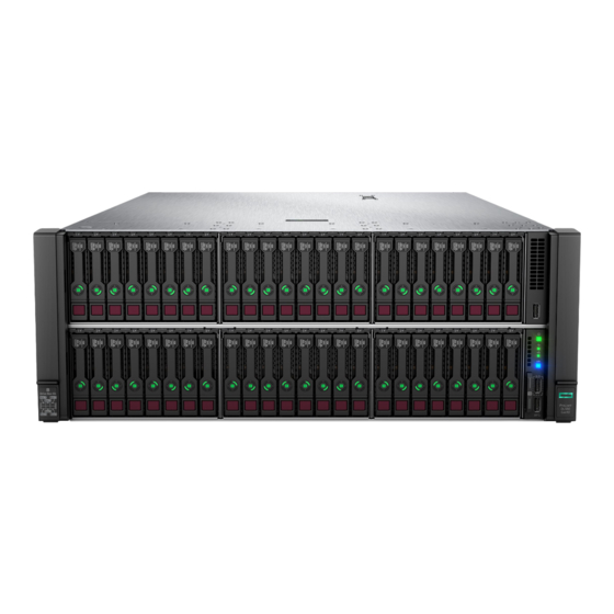
HPE ProLiant DL580 Gen10 Server Maintenance
and Service Guide
Abstract
This document is for the person who installs, administers, and troubleshoots servers and storage systems.
Hewlett Packard Enterprise assumes that you are qualified in the servicing of computer equipment, and trained in
recognizing hazards in products with hazardous energy levels.
Part Number: 878777-401
Published: December 2019
Edition: 10
Advertisement
Table of Contents

Related Manuals for HP ProLiant DL580 Gen10


Summary of Contents for HP ProLiant DL580 Gen10
- Page 1 HPE ProLiant DL580 Gen10 Server Maintenance and Service Guide Abstract This document is for the person who installs, administers, and troubleshoots servers and storage systems. Hewlett Packard Enterprise assumes that you are qualified in the servicing of computer equipment, and trained in recognizing hazards in products with hazardous energy levels.
- Page 2 © Copyright 2017–2019 Hewlett Packard Enterprise Development LP Notices The information contained herein is subject to change without notice. The only warranties for Hewlett Packard Enterprise products and services are set forth in the express warranty statements accompanying such products and services. Nothing herein should be construed as constituting an additional warranty.
-
Page 3: Table Of Contents
Contents Illustrated parts catalog......................7 Mechanical components.........................................7 Air baffle spare parts......................................7 Fan cage spare parts.......................................8 Fan spare parts.......................................... 8 PCIe riser cage spare parts....................................8 4U bezel ear spare parts.......................................8 Mezzanine bracket spare parts..................................8 Miscellaneous blank spare parts..................................9 Cable management arm spare part................................9 System components..........................................9 DIMM spare parts........................................ - Page 4 Power down the server.......................................41 Extending the server from the rack................................41 Removing the server from the rack................................42 Accessing the Systems Insight Display..............................42 Releasing the cable management arm ..............................43 Removing the access panel....................................43 Removing the bezel......................................45 Removing the CPU Mezzanine UPI performance kit.........................45 Removing and replacing a drive blank..................................46 Removing and replacing a hot-plug SAS or SATA drive..........................47 Removing and replacing an NVMe drive...................................47...
- Page 5 Troubleshooting........................99 Troubleshooting resources........................................99 Diagnostic tools........................100 Product QuickSpecs..........................................100 UEFI System Utilities..........................................100 Selecting the boot mode ....................................100 Secure Boot..........................................101 Launching the Embedded UEFI Shell ..............................101 Intelligent Provisioning........................................102 Intelligent Provisioning operation................................102 HPE Insight Remote Support......................................103 USB support............................................103 External USB functionality.................................... 104 HPE Smart Storage Administrator.....................................104 HPE MR Storage Administrator....................................104 HPE InfoSight for servers .......................................105...
- Page 6 Storage Cabling Guidelines......................................136 Cable matrix............................................136 NVMe drive cable matrix....................................138 Universal media bay cabling......................................146 Front panel USB port cabling......................................147 Power switch module/Systems Insight Display module cabling.......................147 SFF HDD drive cage cabling......................................147 NVMe SSD drive cage cabling...................................... 148 Eight-bay NVMe SSD drive cage cabling..............................149 Six-bay SFF HDD/Two-bay NVMe SSD (Premium) drive cage cabling................153 Two-bay SFF (Premium) drive cage..................................
-
Page 7: Illustrated Parts Catalog
Illustrated parts catalog Mechanical components Hewlett Packard Enterprise continually improves and changes product parts. For complete and current supported parts information, see the Hewlett Packard Enterprise (http://www.hpe.com/info/partssurfer). Item Description Air baffle spare parts Fan cage spare parts PCIe riser cage spare parts 3, 4 4U bezel ear spare parts —... -
Page 8: Fan Cage Spare Parts
Description Spare part number Air baffle (one- or two-processor configurations) 881694-001 Air baffle (four-processor configuration) 881690-001 Fan cage spare parts Customer self repair: mandatory Description Spare part number Fan cage with louvers 881686-001 Fan cage bracket kit, right and left 881689-001 Fan spare parts Customer self repair: mandatory... -
Page 9: Miscellaneous Blank Spare Parts
Miscellaneous blank spare parts Customer self repair: mandatory Description Spare part number HDD bay blank kit 777301-001 SFF HDD bay blank 670033-001 SFF hard drive blank 675607-001 2SFF bay blank 875069-001 SFF hard drive blank G8 667276-001 Optical drive blank 684958-001 Power supply blank 775423-001... -
Page 10: Dimm Spare Parts
Item Description DIMM spare parts • HPE 16GB NVDIMM spare part • • HPE Persistent Memory module spare parts Processor spare parts Heatsink spare parts Power supply spare parts PCIe riser board spare parts FlexibleLOM adapter spare parts System board spare parts System battery spare part —... -
Page 11: Hpe 16Gb Nvdimm Spare Part
Description Spare part number DIMM, 64GB PC4-2933Y-L, 2Gx4 P06190-001 DIMM, 64GB PC4-2933Y-R, 4Gx4 P06192-001 DIMM, 128GB PC4-2933Y-L, 2Gx4 P06191-001 DIMM, 128GB PC4-2933Y-L, 4Gx4 P16001-001 DIMM, 128GB PC4-2933Y-L, 4Gx4 P19402-001 HPE 16GB NVDIMM spare part Customer self repair: mandatory Description Spare part number NVDIMM 16GB 1Rx4 NN4-2666V-R 874540-001 HPE Persistent Memory module spare parts... - Page 12 Description Spare part number 2.6 GHz Intel Xeon-G 6132 processor 875722-001 3.2 GHz Intel Xeon-G 6134 processor 875723-001 3.2 GHz Intel Xeon-G 6134M processor 878083-001 3.0 GHz Intel Xeon-G 6136 processor 875724-001 2.0 GHz Intel Xeon-G 6138 processor 874735-001 2.3 GHz Intel Xeon-G 6140 processor 874734-001 2.3 GHz Intel Xeon-G 6140M processor 878084-001...
- Page 13 52XX processors Description Spare part number 2.5 GHz Intel Xeon-G 5215 processor P11610-001 2.6 GHz Intel Xeon-G 5215L processor P11631-001 2.6 GHz Intel Xeon-G 5215M processor P11626-001 3.0 GHz Intel Xeon-G 5217 processor P11611-001 2.3 GHz Intel Xeon-G 5218 processor P11612-001 2.3 GHz Intel Xeon-G 5218B processor P12532-001...
-
Page 14: Heatsink Spare Parts
82XX processors Description Spare part number 2.2 GHz Intel Xeon-P 8253 processor P12011-001 3.8 GHz Intel Xeon-P 8256 processor P12012-001 2.4 GHz Intel Xeon-P 8260 processor P11621-001 2.4 GHz Intel Xeon-P 8260L processor P11633-001 2.4 GHz Intel Xeon-P 8260M processor P11628-001 2.3 GHz Intel Xeon-P 8260Y processor P11638-001... -
Page 15: Flexiblelom Adapter Spare Parts
Description Spare part number 2-Slot tertiary PCIe riser 881683-001 4-Slot x8 Slimline riser 875087-001 6-Slot PCIe riser 881684-001 7-Slot PCIe riser 881682-001 NVMe riser 881698-001 FlexibleLOM adapter spare parts Customer self repair: mandatory Description Spare part number HPE Ethernet 1Gb 4P 331FLR Adapter 789897-001 HPE Ethernet 10Gb 2P 535FLR-T Adapter 854177-001... - Page 16 Fibre channel controllers Description Spare part number HPE SN1600Q 32Gb 1P FC HBA 868140-001 HPE SN1600Q 32Gb 2P FC HBA 868141-001 HPE SN1600E 32Gb 1P FC HBA 869999-001 HPE SN1600E 32Gb 2P FC HBA 870000-001 HPE CN1100R 2P CNA 706801-001 HPE StoreFabric CN1100R-T 10Gb CNA 827605-001 HPE StoreFabric CN1200E 10Gb CNA...
- Page 17 Description Spare part number HPE Ethernet 1Gb 4-port 366T adapter 816551-001 HPE Ethernet 10/25Gb 2P 640FLR-SFP28 adapter 840139-001 HPE Ethernet 10/25Gb 2P 640SFP28 adapter 840140-001 HPE Ethernet 1Gb 4-port 331T adapter 649871-001 HPE Ethernet 10/25Gb 2p 621SFP28 adapter 869570-001 HPE Ethernet 10Gb 2p 522FLR-T CNA 869571-001 HPE Ethernet 4x25Gb 1p 620QSFP28 adapter 840134-001...
-
Page 18: Server Options
Server options Hewlett Packard Enterprise continually improves and changes product parts. For complete and current supported parts information, see the Hewlett Packard Enterprise (http://www.hpe.com/info/partssurfer). Item Description Drive spare parts Drive cage spare parts Processor mezzanine tray spare part Chassis Intrusion Detection Switch spare part Accelerator and GPU spare parts 12G SAS expander board spare part HPE Smart Storage Battery spare part... - Page 19 Hot-plug drive spare parts Customer self repair: mandatory Description Spare part number 300 GB SAS 10K SFF SC DS HDD 872735-001 300 GB SAS 15K SFF SC DS HDD 870792-001 600 GB SAS 10K SFF SC DS HDD 872736-001 600 GB SAS 15K SFF SC 512e DS HDD 870797-001 600 GB SAS 15K SFF SC DS HDD 870794-001...
- Page 20 Description Spare part number 1.92 TB SATA RI M.2 2280 DS SSD 875854-001 M.2 ML/DL SATA riser assembly 882359-001 Solid-state drive SATA spare parts Customer self repair: mandatory Description Spare part number 120 GB SATA MU SFF SC SSD 817096-001 150 GB SATA 6G RI SFF SC DS SSD 869575-001 200 GB SATA WI SFF SC SSD...
- Page 21 Description Spare part number 480 GB SATA RI SFF SC DS SSD P05320-001 480 GB SATA RI SFF SC DS SSD P08567-001 480 GB SATA RI SFF SC MV SSD P18482-001 800 GB SATA 6G WI SFF SC DS SSD 872514-001 800 GB SATA WI SFF SC SSD 805389-001...
- Page 22 Description Spare part number 1.92 TB SATA MU SFF SC MV SSD P18479-001 1.92 TB SATA RI SFF SC DS SSD 878852-001 1.92 TB SATA RI SFF SC DS SSD 875657-001 1.92 TB SATA RI SFF SC DS SSD P05322-001 1.92 TB SATA RI SFF SC DS SSD P08572-001 1.92 TB SATA RI SFF SC MV SSD...
- Page 23 Description Spare part number 800 GB SAS MU SFF SC SSD P20838-001 800 GB SAS WI SFF SC DS SSD P06602-001 800 GB SAS WI SFF SC DS SSD P09948-001 960 GB SAS 12G RI SFF SC DS SSD 872432-001 960 GB SAS MU SFF SC VS DS SSD P10604-001 960 GB SAS RI SFF SC DS SSD...
- Page 24 Description Spare part number 3.84 TB SAS RI SFF SC SSD P20835-001 3.84 TB SAS RI SFF SC VS DS SSD P10639-001 6.4 TB SAS MU SFF SC DS SSD P06583-001 6.4 TB SAS MU SFF SC DS SSD P09926-001 6.4 TB SAS MU SFF SC SSD P20841-001 7.68 TB SAS 12G RI SFF SC DS SSD...
-
Page 25: Drive Cage Spare Parts
Description Spare part number 1.6 TB NVMe x4 MU SFF SCN DS SSD P10649-001 1.6 TB NVMe x4 MU SFF SCN DS SSD P13835-001 1.6 TB NVMe x4 MU SFF SCN SSD 765065-001 1.6 TB NVMe x4 MU SFF SCN DS SSD P13827-001 1.6 TB NVMe x4 WI SFF SCN SSD 765061-001... -
Page 26: Chassis Intrusion Detection Switch Spare Part
Description Spare part number Eight-bay SFF HDD drive cage assembly 780971-001 Eight-bay SFF HDD drive backplane, 12 Gbs 777279-001 874933-001 Two-bay SFF NVMe SSD/Six-bay SFF HDD drive (premium) backplane Two-bay SFF (premium) backplane 875064-001 Eight-bay SFF NVMe drive backplane 872971-001 Chassis Intrusion Detection Switch spare part Customer self repair: mandatory Description... -
Page 27: 12G Sas Expander Board Spare Part
Description Spare part number HPE 2.0TB PCIe x4 MU HH Card 804570-001 HPE 3.2TB PCIe x8 MU HH DS Card 879773-001 HPE 4TB PCIe x4 RI HH DS Card 880418-001 HPE 6.4TB PCIe x8 MU HH DS Card 879774-001 HPE 8TB PCIe x4 RI HH DS Card 880419-001 HPE 1.6TB NVMe x8 MU HH DS Card P10670-001... -
Page 28: Processor Mezzanine Tray Spare Part
Description Spare part number Universal media bay assembly 877958-001 Processor mezzanine tray spare part Customer self repair: optional Description Spare part number Processor mezzanine tray P11742-001 4-port NVMe mezzanine card spare part Customer self repair: optional Description Spare part number 4-port NVMe mezzanine card 877951-001 HPE Trusted Platform Module 2.0 spare part... - Page 29 Description Spare part number Mini SAS/SATA 1041 mm+900 mm cable kit 881700-001 Mini SAS 970 mm+820 mm cable kit 881701-001 Mini SAS/SATA 1x4-1x4 cable 881702-001 NVMe Cable Kit 877983-001 NVMe Cable Kit 881703-001 28 AWG, 3 Pin, PCI to Controller power cable (short) 878645-001 Mini SAS-to-Mini SAS HD, 12G cable kit P03215-001...
-
Page 30: Customer Self Repair
Customer self repair Hewlett Packard Enterprise products are designed with many Customer Self Repair (CSR) parts to minimize repair time and allow for greater flexibility in performing defective parts replacement. If during the diagnosis period Hewlett Packard Enterprise (or Hewlett Packard Enterprise service providers or service partners) identifies that the repair can be accomplished by the use of a CSR part, Hewlett Packard Enterprise will ship that part directly to you for replacement. - Page 31 REMARQUE: Certaines pièces Hewlett Packard Enterprise ne sont pas conçues pour permettre au client d'effectuer lui-même la réparation. Pour que la garantie puisse s'appliquer, Hewlett Packard Enterprise exige que le remplacement de la pièce soit effectué par un Mainteneur Agréé. Ces pièces sont identifiées par la mention "Non" dans le Catalogue illustré. Les pièces CSR sont livrées le jour ouvré...
- Page 32 Servizio di garanzia per i soli componenti La garanzia limitata Hewlett Packard Enterprise può includere un servizio di garanzia per i soli componenti. Nei termini di garanzia del servizio per i soli componenti, Hewlett Packard Enterprise fornirà gratuitamente le parti di ricambio. Per il servizio di garanzia per i soli componenti è...
- Page 33 componente CSR, Hewlett Packard Enterprise le enviará dicho componente directamente para que realice su sustitución. Los componentes CSR se clasifican en dos categorías: • Obligatorio—Componentes cuya reparación por parte del usuario es obligatoria. Si solicita a Hewlett Packard Enterprise que realice la sustitución de estos componentes, tendrá que hacerse cargo de los gastos de desplazamiento y de mano de obra de dicho servicio.
- Page 34 OPMERKING: Sommige Hewlett Packard Enterprise onderdelen zijn niet ontwikkeld voor reparatie door de klant. In verband met de garantievoorwaarden moet het onderdeel door een geautoriseerde Service Partner worden vervangen. Deze onderdelen worden in de geïllustreerde onderdelencatalogus aangemerkt met "Nee". Afhankelijk van de leverbaarheid en de locatie worden CSR-onderdelen verzonden voor levering op de eerstvolgende werkdag. Levering op dezelfde dag of binnen vier uur kan tegen meerkosten worden aangeboden, indien dit mogelijk is gezien de locatie.
- Page 35 Serviço de garantia apenas para peças A garantia limitada da Hewlett Packard Enterprise pode incluir um serviço de garantia apenas para peças. Segundo os termos do serviço de garantia apenas para peças, a Hewlett Packard Enterprise fornece as peças de reposição sem cobrar nenhuma taxa.
- Page 36 Customer self repair...
- Page 37 Customer self repair...
- Page 38 Customer self repair...
-
Page 39: Removal And Replacement Procedures
Removal and replacement procedures Safety considerations Before performing service procedures, review all the safety information. Preventing electrostatic discharge To prevent damaging the system, be aware of the precautions you must follow when setting up the system or handling parts. A discharge of static electricity from a finger or other conductor may damage system boards or other static-sensitive devices. This type of damage may reduce the life expectancy of the device. -
Page 40: Server Warnings And Cautions
This symbol indicates that the component exceeds the recommended weight for one individual to handle safely. WARNING: To reduce the risk of personal injury or damage to the equipment, observe local 51.71 kg occupational health and safety requirements and guidelines for manual material handling. 114.00 lb These symbols, on power supplies or systems, indicate that the equipment is supplied by multiple sources of power. -
Page 41: Preparation Procedures
Preparation procedures Power down the server Before powering down the server for any upgrade or maintenance procedures, perform a backup of critical server data and programs. IMPORTANT: When the server is in standby mode, auxiliary power is still being provided to the system. To power down the server, use one of the following methods: •... -
Page 42: Removing The Server From The Rack
Removing the server from the rack Procedure 1. Power down the server. 2. Extend the server from the rack (Extending the server from the rack). 3. Disconnect the cabling and remove the server from the rack. For more information, see the documentation that ships with the rack mounting option. 4. -
Page 43: Releasing The Cable Management Arm
Releasing the cable management arm Release the cable management arm and then swing the arm away from the rack. Removing the access panel WARNING: To reduce the risk of personal injury from hot surfaces, allow the drives and the internal system components to cool before touching them. - Page 44 Procedure 1. Power down the server. 2. Remove all power: a. Disconnect each power cord from the power source. b. Disconnect each power cord from the server. 3. Do one of the following: Extend the server from the rack (Extending the server from the rack). •...
-
Page 45: Removing The Bezel
Removing the bezel Removing the CPU Mezzanine UPI performance kit Procedure 1. Power down the server. 2. Remove all power: a. Disconnect each power cord from the power source. b. Disconnect each power cord from the server. 3. Do one of the following: Extending the server from the rack. -
Page 46: Removing And Replacing A Drive Blank
To replace the component, reverse the removal procedure. Removing and replacing a drive blank Procedure 1. Press the drive release button. 2. Remove the drive. CAUTION: To prevent improper cooling and thermal damage, do not operate the compute module unless all bays are populated with either a component or a blank. -
Page 47: Removing And Replacing A Hot-Plug Sas Or Sata Drive
Removing and replacing a hot-plug SAS or SATA drive Procedure 1. Determine the status of the drive from the drive LED definitions (Hot-plug drive LED definitions). 2. Back up all data on the drive. 3. Remove the drive. To replace the drive, slide the drive into the bay until it is fully seated, and then close the latch handle. Removing and replacing an NVMe drive Procedure 1. - Page 48 4. Prepare the replacement drive. 5. Install the drive. 6. Observe the LED status of the drive. Removal and replacement procedures...
-
Page 49: Removing And Replacing A Systems Insight Display
Removing and replacing a Systems Insight Display Procedure Power down the server. Remove all power: a. Disconnect each power cord from the power source. b. Disconnect each power cord from the server. Do one of the following: Extend the server from the rack (Extending the server from the rack). •... -
Page 50: Removing A Primary Pcie Riser Cage
Removing a primary PCIe riser cage CAUTION: To prevent damage to the server or expansion boards, power down the server and remove all AC power cords before removing or installing the PCIe riser cage. CAUTION: To avoid damaging the connectors, always install the air baffle into the server before installing the riser cages. -
Page 51: Removing A Butterfly Pcie Riser Cage
Removing a butterfly PCIe riser cage CAUTION: To avoid damaging the connectors, always install the air baffle into the server before installing the riser cages. Procedure 1. Power down the server. 2. Remove all power: a. Disconnect each power cord from the power source. b. - Page 52 CAUTION: To avoid damaging the connectors, always install the air baffle into the server before installing the riser cages. Procedure 1. Power down the server. 2. Remove all power: a. Disconnect each power cord from the power source. b. Disconnect each power cord from the server. 3.
-
Page 53: Removing And Replacing The Fan Cage
Removing and replacing the fan cage Procedure 1. Power down the server. 2. Remove all power: a. Disconnect each power cord from the power source. b. Disconnect each power cord from the server. 3. Do one of the following: Extend the server from the rack (Extending the server from the rack). •... -
Page 54: Removing And Replacing The Hot-Plug Fan
a. Disconnect each power cord from the power source. b. Disconnect each power cord from the server. 3. Do one of the following: Extend the server from the rack (Extending the server from the rack). • • Remove the server from the rack (Removing the server from the rack). 4. -
Page 55: Removing And Replacing The Processor Mezzanine Tray
To replace the component, reverse the removal procedure. Removing and replacing the processor mezzanine tray Procedure 1. Power down the server. 2. Remove all power: a. Disconnect each power cord from the power source. b. Disconnect each power cord from the server. 3. -
Page 56: Removing And Replacing A Dimm
To replace the component, reverse the removal procedure. Removing and replacing a DIMM CAUTION: Failure to properly handle DIMMs can damage the DIMM components and the system board connector. For more information, see the DIMM handling guidelines in the troubleshooting guide for your product on the Hewlett Packard Enterprise website: •... -
Page 57: Dimm-Processor Compatibility
CAUTION: Do not operate the server for long periods with the access panel open or removed. Operating the server in this manner results in improper airflow and improper cooling that can lead to thermal damage. 5. Remove the primary PCIe riser cage (Removing a primary PCIe riser cage). 6. - Page 58 CAUTION: Electrostatic discharge can damage electronic components. Be sure you are properly grounded before beginning this procedure. CAUTION: Failure to properly handle HPE Persistent Memory modules can damage the component and the system board connector. Power down the server. Remove all power: a.
-
Page 59: Hpe Persistent Memory Module-Processor Compatibility
For more information, see Configuring the server for HPE Persistent Memory. 13. If you are relocating the HPE Persistent Memory module to or from another server, see the HPE Persistent Memory module relocation guidelines. HPE Persistent Memory module-processor compatibility HPE Persistent Memory modules are supported only in servers with second-generation Intel Xeon Scalable processors installed. -
Page 60: Hpe Persistent Memory Module Sanitization
◦ Install the HPE Persistent Memory modules in the same DIMM slots in the destination server. ◦ Install the entire interleaved set (all the DIMMs and HPE Persistent Memory modules on the processor) on the destination server. If any of the requirements cannot be met during relocation, do the following: ◦... -
Page 61: Removing And Replacing An Eight-Bay Sff Hdd/Ssd Drive Cage
• Clear: Overwrite user-addressable storage space using standard write commands; might not sanitize data in areas not currently user-addressable (such as bad blocks and over-provisioned areas). • Purge: Overwrite or erase all storage space that might have been used to store data using dedicated device sanitize commands, such that data retrieval is "infeasible using state-of-the-art laboratory techniques."... -
Page 62: Removing And Replacing An Eight-Bay Nvme Ssd Drive Cage
Remove the processor mezzanine tray (Removing and replacing the processor mezzanine tray). • Remove the CPU Mezzanine UPI performance kit (Removing and replacing a CPU Mezzanine UPI performance kit • board). 10. Remove the fan cage (Removing and replacing the fan cage). 11. -
Page 63: Removing And Replacing A Six-Bay Sff Hdd/Two-Bay Nvme Ssd (Premium) Cage
CAUTION: Do not operate the server for long periods with the access panel open or removed. Operating the server in this manner results in improper airflow and improper cooling that can lead to thermal damage. If installed, remove the butterfly riser cage (Removing a butterfly PCIe riser cage). Remove the primary PCIe riser cage (Removing a primary PCIe riser cage). - Page 64 a. Disconnect each power cord from the power source. b. Disconnect each power cord from the server. Do one of the following: Extend the server from the rack (Extending the server from the rack). • • Remove the server from the rack (Removing the server from the rack). Remove the access panel (Removing the access panel).
-
Page 65: Removing And Replacing A Universal Media Bay
To replace the component, reverse the removal procedure. Removing and replacing a universal media bay Procedure Power down the server. Remove all power: a. Disconnect each power cord from the power source. b. Disconnect each power cord from the server. Do one of the following: Extend the server from the rack (Extending the server from the rack). -
Page 66: Removing And Replacing A Two-Bay Sff (Premium) Drive Cage
Remove the processor mezzanine tray (Removing and replacing the processor mezzanine tray). • Remove the CPU Mezzanine UPI performance kit (Removing and replacing a CPU Mezzanine UPI performance kit • board). Remove the fan cage (Removing and replacing the fan cage). 10. - Page 67 CAUTION: Do not operate the server for long periods with the access panel open or removed. Operating the server in this manner results in improper airflow and improper cooling that can lead to thermal damage. If installed, remove the butterfly riser cage (Removing a butterfly PCIe riser cage). Remove the primary PCIe riser cage (Removing a primary PCIe riser cage).
-
Page 68: Removing And Replacing A 4-Port Nvme Mezzanine Card
Removing and replacing a 4-port NVMe mezzanine card Procedure Power down the server. Remove all power: a. Disconnect each power cord from the power source. b. Disconnect each power cord from the server. Do one of the following: Extend the server from the rack (Extending the server from the rack). •... -
Page 69: Removing And Replacing A Riser Board From The Primary Pcie Riser Cage
To replace the component, reverse the removal procedure. Removing and replacing a riser board from the primary PCIe riser cage Procedure 1. Power down the server. 2. Remove all power: a. Disconnect each power cord from the power source. b. Disconnect each power cord from the server. 3. -
Page 70: Removing And Replacing A Riser Board From The Butterfly Pcie Riser Cage
Removing and replacing a riser board from the butterfly PCIe riser cage Procedure 1. Power down the server. 2. Remove all power: a. Disconnect each power cord from the power source. b. Disconnect each power cord from the server. 3. Do one of the following: Extend the server from the rack (Extending the server from the rack). -
Page 71: Removing And Replacing An Expansion Board
Removing and replacing an expansion board Procedure 1. Power down the server. 2. Remove all power: a. Disconnect each power cord from the power source. b. Disconnect each power cord from the server. 3. Do one of the following: Extend the server from the rack (Extending the server from the rack). •... -
Page 72: Removing And Replacing A 12G Sas Expander Card
Removing and replacing a 12G SAS Expander Card To ensure that cables are connected correctly, observe the labels on the cable and component connectors. Be sure that you have the latest firmware for the controllers and the expander card. To download the latest firmware, see the Hewlett Packard Enterprise website (http://www.hpe.com/support/hpesc). -
Page 73: Removing And Replacing A 940Qsfp 56 X16 Adapter And Auxiliary Card
To replace the component, reverse the removal procedure. Removing and replacing a 940QSFP 56 x16 adapter and auxiliary card Procedure Power down the server. Remove all power: a. Disconnect each power cord from the power source. b. Disconnect each power cord from the server. Do one of the following: Extend the server from the rack (Extending the server from the rack). - Page 74 a. Open the retention clip and slide it away from the connectors. b. Gently pull up the top corner of the cable latch door. c. Disconnect the card cables. Remove the adapter (Removing and replacing an expansion board). 10. Disconnect the cables to the adapter. To replace the component: Thread the adapter end of the auxiliary card cables through one of the retention clips provided with the installation kit.
- Page 75 Install the retention clip. Thread the auxiliary cables through the second retention clip. Connect the auxiliary cables to the auxiliary card. Confirm that the orientation of the cables is correct. Removal and replacement procedures...
- Page 76 Install the adapter and auxiliary cards into supported expansion slots. Use the following table to determine the supported slot locations: Processors Adapter slot Auxiliary card slot Two-processor configuration Removal and replacement procedures...
- Page 77 Four-processor configuration Removal and replacement procedures...
-
Page 78: Removing And Replacing A Gpu Card
Install the riser cages. Install the access panel. 10. Connect each power cord to the server. 11. Connect each power cord to the power source. 12. Power up the server. Removing and replacing a GPU card WARNING: To reduce the risk of personal injury, electric shock, or damage to the equipment, remove power from the server by removing the power cord. - Page 79 8. Remove the extender bracket from the GPU card. Retain the extender bracket for installation on the replacement GPU card. To replace the component, reverse the removal procedure. CAUTION: Before installing the riser cage into the server, be sure that the power cables are routed and secured between the GPU card and the riser cage.
-
Page 80: Removing And Replacing A Controller
Removing and replacing a controller Procedure 1. Back up all server data. 2. Power down the server. 3. Remove all power: a. Disconnect each power cord from the power source. b. Disconnect each power cord from the server. 4. Do one of the following: •... -
Page 81: Removing And Replacing A Cpu Mezzanine Upi Performance Kit Board
9. Remove the controller. The primary cage is shown. Your controller might appear different. To replace the component, reverse the removal procedure. Removing and replacing a CPU Mezzanine UPI performance kit board Procedure 1. Power down the server. 2. Remove all power: a. - Page 82 3. Do one of the following: Extend the server from the rack (Extending the server from the rack). • Remove the server from the rack (Removing the server from the rack). • 4. Remove the access panel (Removing the access panel). CAUTION: Do not operate the server for long periods with the access panel open or removed.
-
Page 83: Removing And Replacing A Power Supply
9. Remove the bracket to access the board, and then remove the board. To replace the component, reverse the removal procedure. Removing and replacing a power supply CAUTION: All power supplies installed in the server must have the same output power capacity. Verify that all power supplies have the same part number and label color. -
Page 84: Removing And Replacing The Power Supply Backplane
Procedure 1. To access the rear panel, release the cable management arm ( Releasing the cable management arm ). 2. Disconnect the power cable connected to the power supply. 3. Remove the power supply. To replace the component, reverse the removal procedure. Removing and replacing the power supply backplane Procedure 1. -
Page 85: Removing And Replacing The Flexiblelom
To replace the component, reverse the removal procedure. Removing and replacing the FlexibleLOM Procedure 1. Power down the server. 2. Remove all power: a. Disconnect each power cord from the power source. b. Disconnect each power cord from the server. 3. -
Page 86: Hpe Smart Storage Battery
To replace the component, reverse the removal procedure. HPE Smart Storage Battery The HPE Smart Storage Battery supports the following devices: • HPE Smart Array SR controllers • HPE Smart Array MR controllers A single 96W battery can support up to 24 devices. After the battery is installed, it might take up to two hours to charge. -
Page 87: Removing And Replacing The Secondary Riser Cage Blank
Extend the server from the rack (Extending the server from the rack). • Remove the server from the rack (Removing the server from the rack). • Remove the access panel (Removing the access panel). CAUTION: Do not operate the server for long periods with the access panel open or removed. Operating the server in this manner results in improper airflow and improper cooling that can lead to thermal damage. -
Page 88: Removing And Replacing A Tertiary Riser Cage Blank
3. Do one of the following: Extend the server from the rack (Extending the server from the rack). • Remove the server from the rack (Removing the server from the rack). • 4. Remove the access panel (Removing the access panel). CAUTION: Do not operate the server for long periods with the access panel open or removed. -
Page 89: Removing And Replacing An Intrusion Detection Switch
CAUTION: Do not operate the server for long periods with the access panel open or removed. Operating the server in this manner results in improper airflow and improper cooling that can lead to thermal damage. 5. Remove the tertiary riser cage blank. To replace the component, reverse the removal procedure. -
Page 90: Replacing The System Battery
To replace the component, reverse the removal procedure. Replacing the system battery The system battery provides power to the internal clock. If the server no longer automatically displays the correct date and time, you might need to replace the system battery. WARNING: The computer contains an internal lithium manganese dioxide, a vanadium pentoxide, or an alkaline battery pack. -
Page 91: Removing And Replacing A System Board
CAUTION: Do not operate the server for long periods with the access panel open or removed. Operating the server in this manner results in improper airflow and improper cooling that can lead to thermal damage. 5. If installed, remove the butterfly riser cage (Removing a butterfly PCIe riser cage). 6. - Page 92 a. Disconnect each power cord from the power source. b. Disconnect each power cord from the server. Do one of the following: Extend the server from the rack (Extending the server from the rack). • • Remove the server from the rack (Removing the server from the rack). Remove the access panel (Removing the access panel).
- Page 93 c. Lift the processor heatsink module up and away from the system board. d. Turn the module over and place it on a work surface with the processor facing up. e. Install the dust cover. 13. Remove the Smart Storage batteries (Removing and replacing an HPE Smart Storage Battery). 14.
- Page 94 20. Install the processor heatsink assembly: a. Locate the Pin 1 indicator on the processor carrier and the socket. b. Align the processor heatsink assembly with the heatsink alignment pins and gently lower it down until it sits evenly on the socket. The heatsink alignment pins are keyed.
- Page 95 CAUTION: Be sure to tighten each heatsink nut fully in the order indicated. Otherwise, boot failure or intermittent shutdowns might occur. c. Using a T-30 Torx screwdriver, fully tighten each heatsink nuts in the order indicated on the heatsink label (1 -2 -3 -4) until it no longer turns.
- Page 96 • Four power supply configuration—For redundancy, connect power supplies 1 and 2 to power circuit A, and then connect power supplies 3 and 4 to power circuit B. 25. Power up the server. 26. Ensure all firmware, including option cards and embedded devices, is updated to the same versions to ensure that the latest drivers are being used.
-
Page 97: Re-Entering The Server Serial Number And Product Id
• If HPE Persistent Memory modules are encrypted with local key management, either manually enter the HPE Persistent Memory module passwords in the System Utilities or import the password file from the USB key. • If HPE Persistent Memory modules are encrypted with remote key management, enroll the server iLO in the key management server to provide access to the data on the HPE Persistent Memory modules. -
Page 98: Hpe Trusted Platform Module 2.0 Gen10 Option
3 + 1 Redundancy—In a four-power supply configuration, the server will continue to operate if a single power supply fails. • The server will initiate operating system shutdown if two power supplies fail. No AC power redundancy is possible. 4 + 0 Redundancy—In a four-power supply configuration, there is no power supply redundancy. The server consumes •... -
Page 99: Troubleshooting
Troubleshooting Troubleshooting resources Troubleshooting resources are available for HPE Gen10 server products in the following documents: • Troubleshooting Guide for HPE ProLiant Gen10 servers provides procedures for resolving common problems and comprehensive courses of action for fault isolation and identification, issue resolution, and software maintenance. •... -
Page 100: Diagnostic Tools
Diagnostic tools Product QuickSpecs For more information about product features, specifications, options, configurations, and compatibility, see the product QuickSpecs on the Hewlett Packard Enterprise website (https://www.hpe.com/info/qs). UEFI System Utilities The UEFI System Utilities is embedded in the system ROM. Its features enable you to perform a wide range of configuration activities, including: •... -
Page 101: Secure Boot
Procedure 1. From the System Utilities screen, select System Configuration > BIOS/Platform Configuration (RBSU) > Boot Options > Boot Mode. 2. Select a setting. • UEFI Mode (default)—Configures the system to boot to a UEFI compatible operating system. • Legacy BIOS Mode—Configures the system to boot to a traditional operating system in Legacy BIOS compatibility mode. -
Page 102: Intelligent Provisioning
Prerequisites Embedded UEFI Shell is set to Enabled. Procedure 1. From the System Utilities screen, select Embedded Applications > Embedded UEFI Shell. The Embedded UEFI Shell screen appears. 2. Press any key to acknowledge that you are physically present. This step ensures that certain features, such as disabling Secure Boot or managing the Secure Boot certificates using third-party UEFI tools, are not restricted. -
Page 103: Hpe Insight Remote Support
• Critical boot drivers • Active Health System (AHS) • Erase Utility • Deployment Settings IMPORTANT: • Although your server is preloaded with firmware and drivers, Hewlett Packard Enterprise recommends updating the firmware upon initial setup. Also, downloading and updating the latest version of Intelligent Provisioning ensures the latest supported features are available. -
Page 104: External Usb Functionality
External USB functionality Hewlett Packard Enterprise provides external USB support to enable local connection of USB devices for server administration, configuration, and diagnostic procedures. For additional security, external USB functionality can be disabled through USB options in UEFI System Utilities. HPE Smart Storage Administrator HPE SSA is the main tool for configuring arrays on HPE Smart Array SR controllers. -
Page 105: Hpe Infosight For Servers
Obtain MR Storage Administrator installation files through the Service Pack for ProLiant, or SPP, which you can download from https://www.hpe.com/servers/spp/download. Be sure to use the latest SPP version for the server. For more information about the MR Storage Administrator, see MR Storage Administrator User Guide on the Hewlett Packard Enterprise website https://www.hpe.com/info/P824i-pdocs. -
Page 106: Component Identification
Component identification Front panel components Server with power module Item Description Box 1 — Supported options: Eight-bay SFF HDD/SSD drive cage • Six-bay SFF HDD/Two-bay NVMe SSD (Premium) drive cage • • Eight-bay SFF NVMe SSD drive cage (with only four NVMe drives installed) Box 2 —... - Page 107 Item Description Serial number and iLO information pull tab iLO Service Port (169.254.1.2) Front USB 3.0 port Box 6 — Supported option: Eight-bay SFF HDD/SSD drive cage Box 5 — Supported option: Eight-bay SFF HDD/SSD drive cage Box 4 — Supported options: •...
- Page 108 Item Description Box 1 — Supported options: • Eight-bay SFF HDD/SSD drive cage • Six-bay SFF HDD/Two-bay NVMe SSD (Premium) drive cage Eight-bay SFF NVMe SSD drive cage (with only four NVMe drives • installed) Box 2 — Supported options: Eight-bay SFF HDD/SSD drive cage •...
-
Page 109: Universal Media Bay Components
Universal media bay components Item Description USB 2.0 port Video display port Optical disk drive (optional) Drives (optional) Requires the two-bay SFF (Premium) drive cage Drive bay numbering Eight-bay SFF HDD/SSD drive cage Component identification... - Page 110 Eight-bay SFF NVMe drive cage Six-bay SFF HDD/Two-bay NVMe SSD (Premium) drive cage Component identification...
-
Page 111: Front Panel Leds And Buttons
Two-bay SFF (Premium) drive cage Front panel LEDs and buttons Power switch module Component identification... - Page 112 Systems Insight Display module (optional) Item Description Status Power On/Standby button and Solid green = System on system power LED Flashing green (1 Hz/cycle per sec) = Performing power on sequence Solid amber = System in standby Off = No power present Health LED Solid green = Normal Flashing green (1 Hz/cycle per sec) = iLO is rebooting...
-
Page 113: Uid Button Functionality
Item Description Status NIC status LED Solid green = Link to network Flashing green (1 Hz/cycle per sec) = Network active Off = No network activity UID button/LED Solid blue = Activated Flashing blue: • 1 Hz/cycle per sec = Remote management or firmware upgrade in progress •... -
Page 114: Systems Insight Display Leds
Subsystem LED behavior System board PCIe slots 7 flashes Power backplane or storage backplane 8 flashes Power supply 9 flashes Systems Insight Display LEDs The Systems Insight Display LEDs represent the system board layout. The display enables diagnosis with the access panel installed. -
Page 115: Systems Insight Display Combined Led Descriptions
Description Status Power supply LEDs Off = Normal Solid amber = Power subsystem degraded, power supply failure, or input power lost. PCI riser LED Off = Normal Amber = Incorrectly installed PCI riser cage Over temp LED Off = Normal Amber = High system temperature detected Proc DIMM Group LED Off = Normal... -
Page 116: Drives
Systems Insight Display LED Health LED System power Status and color DIMM (amber) Green One or more DIMMs have failed. DIMM (amber) Amber Green DIMM in slot X is in a pre-failure condition. Over temp (amber) Amber Green The Health Driver has detected a cautionary temperature level. -
Page 117: Hot-Plug Drive Led Definitions
Hot-plug drive LED definitions Item Status Definition Locate Solid blue The drive is being identified by a host application. Flashing blue The drive carrier firmware is being updated or requires an update. Activity ring Rotating green Drive activity. No drive activity. Do not remove Solid white Do not remove the drive. - Page 118 CAUTION: Do not remove an NVMe SSD from the drive bay while the Do not remove LED is flashing. The Do not remove LED flashes to indicate that the device is still in use. Removing the NVMe SSD before the device has completed and ceased signal/traffic flow can cause loss of data.
-
Page 119: Sas/Sata Drive Components And Leds
Item Status Definition Flashing green The drive ejection request is pending. The drive has been ejected. SAS/SATA drive components and LEDs Item Description Status Locate • Solid blue = The drive is being identified by a host application. • Flashing blue = The drive carrier firmware is being updated or requires an update. -
Page 120: Drive Guidelines
Drive guidelines CAUTION: Do not remove an NVMe SSD from the drive bay while the Do Not Remove button LED is flashing. The Do Not Remove button LED flashes to indicate the device is still in use. Removal of the NVMe SSD before the device has completed and ceased signal/traffic flow can cause loss of data. - Page 121 Item Description Rear USB 2.0 ports (2) Rear USB 3.0 ports (2) UID LED FlexibleLOM (optional) Rear panel with optional butterfly riser cage Item Description Primary PCIe riser slots 1-7 Butterfly PCIe riser slots 8-16 (optional) Power supplies (4) Serial port iLO Management Port Video port Rear USB 2.0 ports (2)
-
Page 122: Rear Panel Leds
Rear panel LEDs Item Description Status Activity LED Off = No network activity Solid green = Link to network Flashing green = Network activity Link LED Off = No network link Green = Network link UID LED Solid blue = Activated Flashing blue: •... -
Page 123: Fan Bay Numbering
LED Status Description System is off or power supply has failed. Solid Green Normal Fan bay numbering The server requires 12 fans, with two fans per bay. Component identification... -
Page 124: System Board Components
System board components Item Description FlexibleLOM connector Primary PCIe riser connector (processor 1 required) x4 SATA port 1 x4 SATA port 2 Upper processor mezzanine connector — Power (2) Upper processor mezzanine connector — Signals (2) USB 3.0 (2) x1 SATA port System maintenance switch Front USB 3.0 connector and iLO Service Port x1 SATA port / Optical Drive port... -
Page 125: System Maintenance Switch Descriptions
Item Description Energy pack connector 2 (processor mezzanine board) Universal media bay USB/Display port connector Intrusion detection switch connector Power supply connectors (PS3, PS4) Power supply connectors (PS1, PS2) Secondary PCIe riser connector (processor 2 required) System battery Tertiary PCIe riser connector (processor 2 required) TPM connector microSD connector The energy pack connected to this connector provides backup power to the DIMM slots and controllers installed on the system board. -
Page 126: Processor, Heatsink, And Socket Components
When the system maintenance switch position 6 is set to the On position, the system is prepared to restore all configuration settings to their manufacturing defaults. When the system maintenance switch position 6 is set to the On position and Secure Boot is enabled, some configurations cannot be restored. -
Page 127: Dimm Label Identification
System board DIMM slots Processor mezzanine board DIMM slots DIMM label identification To determine DIMM characteristics, see the label attached to the DIMM. The information in this section helps you to use the label to locate specific information about the DIMM. Component identification... - Page 128 Item Description Example Capacity 8 GB 16 GB 32 GB 64 GB 128 GB Rank 1R = Single rank 2R = Dual rank 4R = Quad rank 8R = Octal rank Data width on DRAM x4 = 4-bit x8 = 8-bit x16 = 16-bit Memory generation PC4 = DDR4...
-
Page 129: Hpe Persistent Memory Module Label Identification
Item Description Example CAS latency P = CAS 15-15-15 T = CAS 17-17-17 U = CAS 20-18-18 V = CAS 19-19-19 (for RDIMM, LRDIMM) V = CAS 22-19-19 (for 3DS TSV LRDIMM) Y = CAS 21-21-21 (for RDIMM, LRDIMM) Y = CAS 24-21-21 (for 3DS TSV LRDIMM) DIMM type R = RDIMM (registered) L = LRDIMM (load reduced) -
Page 130: Drive Cage Backplane Identification
For more information about product features, specifications, options, configurations, and compatibility, see the product QuickSpecs on the Hewlett Packard Enterprise website (https://www.hpe.com/support/persistentmemoryQS). Drive cage backplane identification Eight-bay SFF HDD/SSD drive cage backplane Eight-bay SFF NVMe SSD drive cage backplane Component identification... - Page 131 Two-bay NVMe/Six-bay SFF HDD (Premium) drive cage backplane Two-bay SFF (Premium) drive cage backplane Component identification...
-
Page 132: Riser Board Components
Riser board components 4 port Slimline riser Item Description 1–4 x8 Slimline NVMe connectors 6 slot riser board Item Description GPU power connectors (2) Controller backup power connectors (6) x16 connectors (2) Table Continued Component identification... - Page 133 Item Description x8 connectors (4) NVMe slimline connector J4 NVMe slimline connector J3 7 slot riser board Item Description GPU power connectors (2) Controller backup power connectors (7) x8 connectors (4) x16 connectors (3) Tertiary riser board Component identification...
-
Page 134: Hpe 12G Sas Expander Card Port Numbering
Item Description x8 connectors (2) Controller backup power connectors HPE 12G SAS Expander Card port numbering HPE Smart Array P824i-p MR Gen10 Controller Components Component identification... -
Page 135: Hpe Infiniband Hdr/Ethernet 940Qsfp 56X16 Adapter Leds
Item Description Internal SAS port 1i Internal SAS port 2i Internal SAS port 3i Internal SAS port 4i Controller backup power cable connector Internal SAS port 5i Internal SAS port 6i HPE InfiniBand HDR/Ethernet 940QSFP 56x16 adapter LEDs Link LED status Description A link has not been established. -
Page 136: Cabling
Cabling Storage Cabling Guidelines When installing cables, observe the following: • All ports are labeled: ◦ System board ports ◦ Controller ports ◦ 12G SAS Expander ports • Most data cables have labels near each connector with destination port information. •... - Page 137 Option kit Cable part number* From Power cable part number 8SFF SAS/SATA drive cage (mini SAS) 870489-001 Drive backplane Primary riser 870479-001 (drive boxes 1– cage Tertiary riser cage 12G SAS Expander 12G SAS — 870499-001 2SFF SAS port Expander HPE Smart Array p824i-p MR Gen 10 —...
-
Page 138: Nvme Drive Cable Matrix
Option kit Cable part number* From Optical disk drive 869949-001 Component System board Systems Insight Display Included with Component System board component * To order spare cables, use the following kits and spare part numbers. USB 3.0 Ext. 600mm+SASPWR BP cable kit (881699-001) Optical drive cable (784623-001) GPU kits Option kit... - Page 139 # of NVMe Processor Cable part number * From Power cable part drives quantity number * supported 869957-001 Drive box 2, 8SFF (6+2) Primary 6 slot riser 870479-001 Premium drive cage 869957-001 Drive box 4, 2SFF Premium Primary 6 slot riser 870479-001 drive cage 869957-001 Drive box 4, 2SFF Premium...
- Page 140 Server riser configuration: Primary riser cage—6 slot riser installed • Butterfly riser cage—6 slot and 2 slot risers installed • # of NVMe Processor Cable part number From Power cable drives quantity part number supported 869957-001 Drive box 2, 8SFF (6+2) Primary 6 slot riser 870479-001 Premium drive cage...
- Page 141 # of NVMe Processor Cable part number From Power cable drives quantity part number supported Drive box 3, 8SFF (6+2) Primary 6 slot riser Premium drive cage 870508-001 Drive box 2, 8-NVMe drive Primary 6 slot riser 870479-001 cage Butterfly 6 slot riser 869957-001 Drive box 1, 8SFF (6+2) Primary 6 slot riser...
- Page 142 # of NVMe Processor Cable part number From Power cable drives quantity part number supported Drive box 3, 8SFF (6+2) Primary 6 slot riser Premium drive cage 869957-001 Drive box 2, 8SFF (6+2) Primary 6 slot riser 870479-001 Premium drive cage Drive box 4, 2SFF Premium Primary 6 slot riser drive cage...
- Page 143 # of NVMe Processor Cable part number From Power cable drives quantity part number supported 869957-001 Drive box 4, 2SFF Premium Butterfly 6 slot riser 870479-001 drive cage 869957-001 Drive box 2, 8SFF (6+2) Butterfly 6 slot riser 870479-001 Premium drive cage 869957-001 Drive box 4, 2SFF Premium Butterfly 6 slot riser...
- Page 144 # of NVMe Processor Cable part number From Power cable drives quantity part number supported 870508-001 Drive box 2, 8-NVMe drive 4 port mezzanine card 870479-001 cage Drive box 3, 8-NVMe drive Primary 4 port riser cage 869957-001 Drive box 4, 2SFF Premium Butterfly 6 slot riser drive cage 870508-001...
- Page 145 # of NVMe Processor Cable part number From Power cable drives quantity part number supported 869957-001 Drive box 3, 8-NVMe drive Primary 4 port riser cage 20 ** 870508-001 Drive box 1, 8SFF (6+2) Butterfly 6 slot riser 870479-001 Premium drive cage Drive box 2, 8-NVMe drive 4 port mezzanine card cage...
-
Page 146: Universal Media Bay Cabling
• NVMe cable kit (877983-001) • NVMe cable kit (881703-001) • USB 3.0 Ext. 600mm+SASPWR BP cable kit (881699-001) Universal media bay cabling With optional optical disk drive With optional 2SFF drive cage Cabling... -
Page 147: Front Panel Usb Port Cabling
Front panel USB port cabling Power switch module/Systems Insight Display module cabling SFF HDD drive cage cabling CAUTION: To avoid damage to the cables and server components, always route cables flat against the server walls, and separate the cables as they enter the primary riser cage. Bundled cables can be pinched or damaged when installing the fan cage or primary riser cage. -
Page 148: Nvme Ssd Drive Cage Cabling
Drive cages to primary PCIe riser Drive cages to tertiary riser slot NVMe SSD drive cage cabling CAUTION: To avoid damage to the cables and server components, always route cables flat against the server walls, and separate the cables as they enter the primary riser cage. Bundled cables can be pinched or damaged when installing the fan cage or primary riser cage. -
Page 149: Eight-Bay Nvme Ssd Drive Cage Cabling
Six-bay SFF HDD/Two-bay NVMe SSD (Premium) drive cage cabling • • Two-bay SFF (Premium) drive cage Eight-bay NVMe SSD drive cage cabling CAUTION: To avoid damage to the cables and server components, always route cables flat against the server walls, and separate the cables as they enter the primary riser cage. - Page 150 Drive box 2 to primary riser cage (4-drive configuration) Drive box 2 to primary and butterfly riser cages (6-drives or fewer configuration) Cabling...
- Page 151 Drive box 2 to primary and butterfly riser cages (8-drive configuration) Drive box 2 to 4 port mezzanine card Cabling...
- Page 152 Drive box 3 to primary 4 port riser Drive box 2 to 4 port mezzanine card, Drive box 3 to primary 4 port riser (16-drive configuration) Cabling...
-
Page 153: Six-Bay Sff Hdd/Two-Bay Nvme Ssd (Premium) Drive Cage Cabling
20-drive configuration 16-drive configuration, plus the following: • Drive box 1 (six-bay HDD/two-bay NVMe Premium drive cage), connected to the 6 slot riser installed in the butterfly riser cage. • Drive box 4 (universal media bay with two-bay SFF Premium drive cage), connected to the 6 slot riser installed in the butterfly riser cage. - Page 154 Drive box 1 • NVMe drives cabled to the secondary riser cage • SAS/SATA drives cabled to the primary riser cage Drive box 2 or 5 • NVMe drives cabled to the primary riser cage • SAS/SATA drives cabled to the primary riser cage Cabling...
-
Page 155: Two-Bay Sff (Premium) Drive Cage
Drive box 3 or 6 • NVMe drives cabled to the primary riser cage • SAS/SATA drives cabled to the primary riser cage Two-bay SFF (Premium) drive cage CAUTION: To avoid damage to the cables and server components, always route cables flat against the server walls, and separate the cables as they enter the primary riser cage. -
Page 156: 12G Sas Expander Cabling
From drive box 4, to the primary riser cage From drive box 4, to the butterfly riser cage 12G SAS expander cabling CAUTION: To avoid damage to the cables and server components, always route cables flat against the server walls, and separate the cables as they enter the primary riser cage. -
Page 157: Hpe Smart Array Mr Gen10 Controller Cabling
24-drive configuration Cables from the lower drive box backplanes (boxes 4–6) are routed to the SAS expander card installed in the primary riser cage. 48-drive configuration • Cables from the lower drive box backplanes are routed as shown in the 24-drive configuration. •... - Page 158 Controller backup power cable Using the shorter of the two cables provided, connect the controller backup power cable to the controller backup power connector on the riser board. 24-drive configuration Cables from the lower drive box backplanes (boxes 4–6) are routed to the controller installed in the primary riser cage. Cabling...
-
Page 159: Hpe Smart Storage Battery Cabling
48-drive configuration • Cables from the lower drive box backplanes are routed as shown in the 24-drive configuration. • Cables from the upper drive box backplanes (boxes 1–3) are routed to the controller installed in the butterfly riser cage. HPE Smart Storage Battery cabling Cable Description Blue... - Page 160 NOTE: This server supports only the HPE Smart Storage Battery. Cabling...
-
Page 161: Specifications
Specifications Environmental specifications Specification Value System Inlet Temperature, Standard Operating Support — Operating 10°C to 35°C (50°F to 95°F) Non-operating -30°C to 60°C (-22°F to 140°F) Relative humidity (non-condensing) — Operating Minimum to be the higher (more moisture) of -12°C (10.4°F) dew point or 8% relative humidity Maximum to be 24°C (75.2°F) dew point or 90% relative humidity... -
Page 162: System Inlet Temperature, Extended Ambient Operating Support
System Inlet Temperature, Extended Ambient Operating Support Specification Value System Inlet Temperature, Extended Ambient Operating — Support — For approved hardware configurations, the supported system inlet range is extended to be 5°C to 10°C (41°F to 50°F) and 35°C to 40°C (95°F to 104°F) All temperature ratings shown are for sea level with an altitude derating of 1.0 °C per every 175 m (1.8°F per every 574 ft) above 900 m (2953 ft) to a maximum of 3050 m... -
Page 163: Hpe 800W Flex Slot Platinum Hot-Plug Low Halogen Power Supply
HPE 800W Flex Slot Platinum Hot-plug Low Halogen Power Supply Specification Value Input requirements — Rated input voltage 100 VAC to 127 VAC 200 VAC to 240 VAC 240 VDC for China only Rated input frequency 50 Hz to 60 Hz Not applicable to 240 VDC Rated input current 9.1 A at 100 VAC... -
Page 164: Hpe 800W Flex Slot -48Vdc Hot-Plug Low Halogen Power Supply
HPE 800W Flex Slot -48VDC Hot-plug Low Halogen Power Supply Specification Value Input requirements — Rated input voltage -40 VDC to -72 VDC -48 VDC nominal input Rated input current 22.1 A at -40 VDC input 18.2 A at -48 VDC input, nominal input 12.0 A at -72 VDC input Rated input power (W) 874 W at -40 VDC input... -
Page 165: Hpe 1600W Flex Slot Platinum Hot-Plug Low Halogen Power Supply
CAUTION: This equipment is designed to permit the connection of the earthed conductor of the DC supply circuit to the earthing conductor at the equipment. If this connection is made, all of the following must be met: • This equipment must be connected directly to the DC supply system earthing electrode conductor or to a bonding jumper from an earthing terminal bar or bus to which the DC supply system earthing electrode conductor is connected. -
Page 166: Websites
Websites General websites Hewlett Packard Enterprise Information Library https://www.hpe.com/info/EIL Single Point of Connectivity Knowledge (SPOCK) Storage compatibility matrix https://www.hpe.com/storage/spock Storage white papers and analyst reports https://www.hpe.com/storage/whitepapers For additional websites, see Support and other resources. Websites... -
Page 167: Support And Other Resources
Support and other resources Accessing Hewlett Packard Enterprise Support • For live assistance, go to the Contact Hewlett Packard Enterprise Worldwide website: https://www.hpe.com/info/assistance • To access documentation and support services, go to the Hewlett Packard Enterprise Support Center website: https://www.hpe.com/support/hpesc Information to collect •... -
Page 168: Remote Support
IMPORTANT: Access to some updates might require product entitlement when accessed through the Hewlett Packard Enterprise Support Center. You must have an HPE Passport set up with relevant entitlements. Remote support Remote support is available with supported devices as part of your warranty or contractual support agreement. It provides intelligent event diagnosis, and automatic, secure submission of hardware event notifications to Hewlett Packard Enterprise, which will initiate a fast and accurate resolution based on your product's service level. -
Page 169: Documentation Feedback
Additional regulatory information Hewlett Packard Enterprise is committed to providing our customers with information about the chemical substances in our products as needed to comply with legal requirements such as REACH (Regulation EC No 1907/2006 of the European Parliament and the Council). A chemical information report for this product can be found at: https://www.hpe.com/info/reach For Hewlett Packard Enterprise product environmental and safety information and compliance data, including RoHS and REACH, see:...
Need help?
Do you have a question about the ProLiant DL580 Gen10 and is the answer not in the manual?
Questions and answers