Table of Contents
Advertisement
Quick Links
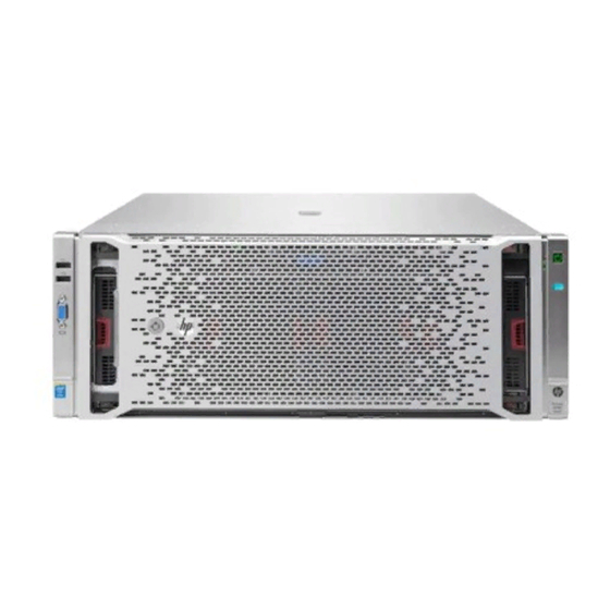
HPE ProLiant DL580 Gen9 Server
Maintenance and Service Guide
Abstract
This document describes service procedures for the HPE ProLiant DL580 Gen8 Server. This document is intended for experienced service
technicians. Hewlett Packard Enterprise assumes that you are qualified in the servicing of computer equipment, are trained in recognizing
hazards in products with hazardous energy levels, and are familiar with weight and stability precautions for rack installations.
Part Number: 799242-002
May 2016
Edition: 3
Advertisement
Table of Contents

Related Manuals for HP ProLiant DL580 Gen9


Summary of Contents for HP ProLiant DL580 Gen9
- Page 1 HPE ProLiant DL580 Gen9 Server Maintenance and Service Guide Abstract This document describes service procedures for the HPE ProLiant DL580 Gen8 Server. This document is intended for experienced service technicians. Hewlett Packard Enterprise assumes that you are qualified in the servicing of computer equipment, are trained in recognizing hazards in products with hazardous energy levels, and are familiar with weight and stability precautions for rack installations.
- Page 2 © Copyright 2015, 2016 Hewlett Packard Enterprise Development LP The information contained herein is subject to change without notice. The only warranties for Hewlett Packard Enterprise products and services are set forth in the express warranty statements accompanying such products and services. Nothing herein should be construed as constituting an additional warranty.
-
Page 3: Table Of Contents
Top SAS backplane ..............................62 Express Bay Bridge card ............................64 Express Bay backplane ............................65 Power daughter board ............................67 Power supply backplane ............................68 FlexibleLOM ................................68 Battery ..................................69 HP Trusted Platform Module ..........................70 Troubleshooting ............................72 Contents 3... - Page 4 Troubleshooting resources ............................. 72 Diagnostic tools ............................73 HPE UEFI System Utilities ............................. 73 Using UEFI System Utilities ......................... 73 Flexible boot control ............................ 73 Restoring and customizing configuration settings ..................74 Secure Boot configuration ........................... 74 Embedded UEFI shell..........................75 Embedded Diagnostics option ........................
- Page 5 Documentation feedback ........................106 Index ..............................107 Contents 5...
-
Page 6: Customer Self Repair
Customer self repair Hewlett Packard Enterprise products are designed with many Customer Self Repair (CSR) parts to minimize repair time and allow for greater flexibility in performing defective parts replacement. If during the diagnosis period Hewlett Packard Enterprise (or Hewlett Packard Enterprise service providers or service partners) identifies that the repair can be accomplished by the use of a CSR part, Hewlett Packard Enterprise will ship that part directly to you for replacement. - Page 7 • Obligatoire—Pièces pour lesquelles la réparation par le client est obligatoire. Si vous demandez à Hewlett Packard Enterprise de remplacer ces pièces, les coûts de déplacement et main d'œuvre du service vous seront facturés. • Facultatif—Pièces pour lesquelles la réparation par le client est facultative. Ces pièces sont également conçues pour permettre au client d'effectuer lui-même la réparation.
- Page 8 NOTA: alcuni componenti Hewlett Packard Enterprise non sono progettati per la riparazione da parte del cliente. Per rispettare la garanzia, Hewlett Packard Enterprise richiede che queste parti siano sostituite da un centro di assistenza autorizzato. Tali parti sono identificate da un "No" nel Catalogo illustrato dei componenti.
- Page 9 Support Center anrufen und sich von einem Mitarbeiter per Telefon helfen lassen. Den Materialien von Hewlett Packard Enterprise, die mit einem CSR-Ersatzteil geliefert werden, können Sie entnehmen, ob das defekte Teil an Hewlett Packard Enterprise zurückgeschickt werden muss. Wenn es erforderlich ist, das defekte Teil an Hewlett Packard Enterprise zurückzuschicken, müssen Sie dies innerhalb eines vorgegebenen Zeitraums tun, in der Regel innerhalb von fünf (5) Geschäftstagen.
- Page 10 deberá hacerlo en el periodo de tiempo especificado, normalmente cinco días laborables. Los componentes defectuosos deberán devolverse con toda la documentación relacionada y con el embalaje de envío. Si no enviara el componente defectuoso requerido, Hewlett Packard Enterprise podrá cobrarle por el de sustitución.
- Page 11 Enterprise u voor het vervangende onderdeel kosten in rekening brengen. Bij reparatie door de klant betaalt Hewlett Packard Enterprise alle verzendkosten voor het vervangende en geretourneerde onderdeel en kiest Hewlett Packard Enterprise zelf welke koerier/transportonderneming hiervoor wordt gebruikt. Neem contact op met een Service Partner voor meer informatie over het Customer Self Repair programma van Hewlett Packard Enterprise.
- Page 12 Para obter mais informações sobre o programa de reparo feito pelo cliente da Hewlett Packard Enterprise, entre em contato com o fornecedor de serviços local. Para o programa norte-americano, visite o site da Hewlett Packard Enterprise (http://www.hpe.com/support/selfrepair). Serviço de garantia apenas para peças A garantia limitada da Hewlett Packard Enterprise pode incluir um serviço de garantia apenas para peças.
- Page 13 Customer self repair 13...
- Page 14 Customer self repair 14...
- Page 15 Customer self repair 15...
-
Page 16: Illustrated Parts Catalog
Illustrated parts catalog Mechanical components Hewlett Packard Enterprise continually improves and changes product parts. For complete and current supported parts information, see the Hewlett Packard Enterprise PartSurfer website (http://www.hpe.com/info/partssurfer). Item Description Spare part Customer number self repair (on page 6) Server access panel 735510-001 Mandatory... - Page 17 No—Some Hewlett Packard Enterprise parts are not designed for customer self repair. In order to satisfy the customer warranty, Hewlett Packard Enterprise requires that an authorized service provider replace the part. These parts are identified as "No" in the Illustrated Parts Catalog. Obligatoire—Pièces pour lesquelles le client doit procéder lui-même aux réparations.
- Page 18 Opcional—Peças cujo reparo feito pelo cliente é opcional. Essas peças também são projetadas para o reparo feito pelo cliente. No entanto, se desejar que a Hewlett Packard Enterprise as substitua, pode haver ou não a cobrança de taxa adicional, dependendo do tipo de serviço de garantia destinado ao produto. Não—Algumas peças da Hewlett Packard Enterprise não são projetadas para o reparo feito pelo cliente.
-
Page 19: System Components
System components Hewlett Packard Enterprise continually improves and changes product parts. For complete and current supported parts information, see the Hewlett Packard Enterprise PartSurfer website (http://www.hpe.com/info/partssurfer). Item Description Spare part Customer number self repair (on page 6) Heatsink 735514-001 Optional Processor memory drawer 735518-001 Optional... - Page 20 Spare part Customer Item Description number self repair (on page 6) c) Intel Xeon E7-8870v3 (2.1 GHz/140 W) 802280-001 Optional Processor with jacket* d) Intel Xeon E7-8860v3 (2.2 GHz/140 W) 802281-001 Optional Processor with jacket* e) Intel Xeon E7-4850v3 (2.2 GHz/115 W) 802282-001 Optional Processor with jacket*...
- Page 21 Spare part Customer Item Description number self repair (on page 6) Designed for Intel Xeon E7 v3 processors — — a) 8 GB, PC4-2133P-R, 1Gx4 774170-001 Mandatory b) 16 GB, PC4-2133P-R, 1Gx4 774172-001 Mandatory c) 32 GB, PC4-2133P-L, 1Gx4 774174-001 Mandatory d) 16 GB, PC4-2133P-L, 1Gx4 774173-001...
- Page 22 Spare part Customer Item Description number self repair (on page 6) h) 800 GB, SATA, SFF, 6G 692167-001 Mandatory i) 400 GB, SATA, SFF, 6G 692166-001 Mandatory j) 200 GB, SATA, SFF, 6G 692165-001 Mandatory k) 100 GB, SATA, SFF, 6G 692164-001 Mandatory FlexibleLOM...
- Page 23 Optional—Parts for which customer self repair is optional. These parts are also designed for customer self repair. If, however, you require that Hewlett Packard Enterprise replace them for you, there may or may not be additional charges, depending on the type of warranty service designated for your product. No—Some Hewlett Packard Enterprise parts are not designed for customer self repair.
- Page 24 Obrigatório—Peças cujo reparo feito pelo cliente é obrigatório. Se desejar que a Hewlett Packard Enterprise substitua essas peças, serão cobradas as despesas de transporte e mão-de-obra do serviço. Opcional—Peças cujo reparo feito pelo cliente é opcional. Essas peças também são projetadas para o reparo feito pelo cliente.
-
Page 25: Removal And Replacement Procedures
For more information about telco rack solutions, refer to the RackSolutions.com website (http://www.racksolutions.com/hp). • Remove the server from the rack (on page 27). -
Page 26: Power Down The Server
• Remove the access panel (on page 28). If you are servicing internal components, remove the access panel. • Remove the processor memory drawer shipping screws ("Processor memory drawer shipping screw locations" on page 29). • Remove the processor memory drawer (on page 29). •... -
Page 27: Remove The Server From The Rack
Extend the server on the rack rails until the server rail-release latches engage. After performing the installation or maintenance procedure, slide the server into the rack by pressing the server rail-release latches. Remove the server from the rack WARNING: To reduce the risk of personal injury or equipment damage, be sure that the rack is adequately stabilized before extending a component from the rack. -
Page 28: Remove The Access Panel
To remove the server from the rack: Pull down the quick-release levers on each side of the server to release the server from the rack. If necessary, loosen the rack screws. Extend the server on the rack rails until the server rail-release latches engage. Remove the server from the rack. -
Page 29: Processor Memory Drawer Shipping Screw Locations
Processor memory drawer shipping screw locations Two orange shipping screws secure the processor memory drawer in place during shipping. You must remove the screws to access the processor memory drawer. Retain the screws for future use. Remove the processor memory drawer WARNING: The processor memory drawer weighs more than 11.3 kg (25.0 lb). -
Page 30: Remove The Processor Memory Drawer Cover
Remove the processor memory drawer cover Remove the processor memory drawer shipping screws, if installed. Retain the screws for future use ("Processor memory drawer shipping screw locations" on page 29). Remove the processor memory drawer (on page 29). Remove the processor memory drawer cover. Remove the SPI board To remove the component: Power down the server (on page 26). -
Page 31: Installing The Server Into The Rack
Extend the processor memory drawer approximately 2.54 to 5.1 cm (1 to 2 inches). Loosen the thumbscrews on the SPI board, and then lift the SPI board to access the cables. Disconnect all cables from the SPI board. IMPORTANT: If replacing the SPI board or clearing NVRAM, you must re-enter the server serial number through the Advanced System ROM options in UEFI System Utilities ("Re-entering the server serial number and product ID"... - Page 32 Connect peripheral devices to the server. For information on identifying connectors, see "SPI board components (on page 86)." WARNING: To reduce the risk of electric shock, fire, or damage to the equipment, do not plug telephone or telecommunications connectors into RJ-45 connectors. Connect the power cord to the rear of the server.
- Page 33 Connect the power cord to the AC power source. WARNING: To reduce the risk of electric shock or damage to the equipment: • Do not disable the power cord grounding plug. The grounding plug is an important safety feature. • Plug the power cord into a grounded (earthed) electrical outlet that is easily accessible at all times.
-
Page 34: 4U Rack Bezel
4U rack bezel Remove the component as indicated. To replace the component, reverse the removal procedure. Remove the component as indicated. To replace the component, reverse the removal procedure. Removal and replacement procedures 34... -
Page 35: Drive Blank
Drive blank Remove the component as indicated. To replace the component, reverse the removal procedure. Drive To remove the component: Determine the status of the drive from the drive LED definitions ("Hot-plug drive LED definitions" on page 93). Back up all server data on the drive. Remove the drive. -
Page 36: Left Bezel (Usb/Video)
Install the drive. Determine the status of the drive from the drive LED definitions ("Hot-plug drive LED definitions" on page 93). Left bezel (USB/video) Power down the server (on page 26). Remove all power: Disconnect each power cord from the power source. Disconnect each power cord from the server. -
Page 37: Usb/Video/Discovery Services Cable
Disconnect the cable from the bezel. To replace the component, reverse the removal procedure. USB/video/Discovery Services cable Power down the server (on page 26). Remove all power: Disconnect each power cord from the power source. Disconnect each power cord from the server. Extend the server from the rack (on page 26). -
Page 38: Right Bezel (Uid/Power/Sid)
Disconnect the cable from the bezel. Disconnect the cable from the SPI board. To replace the component, reverse the removal procedure. Right bezel (UID/power/SID) Power down the server (on page 26). Remove all power: Disconnect each power cord from the power source. Disconnect each power cord from the server. -
Page 39: Uid/Power/Sid Cable
Using a Torx T-10 screwdriver, remove the screws securing the bezel to the chassis, and then remove the assembly from the server. Disconnect the cable from the bezel. To replace the component, reverse the removal procedure. UID/power/SID cable Power down the server (on page 26). Remove all power: Disconnect each power cord from the power source. -
Page 40: Hot-Plug Power Supply
Remove the right bezel ("Right bezel (UID/power/SID)" on page 38). Disconnect the cable from the SPI board. To replace the component, reverse the removal procedure. Hot-plug power supply The server supports up to four hot-plug power supplies. Install all power supplies to provide full redundancy. -
Page 41: Power Supply Blank
Remove the failed power supply. To replace the component, reverse the removal procedure. Power supply blank Remove the component as indicated. To replace the component, reverse the removal procedure. Expansion board CAUTION: To prevent improper cooling and thermal damage, do not operate the server unless all expansion slots have either an expansion slot cover or an expansion board installed. -
Page 42: Expansion Slot Cover
Open the expansion board retainer. Disconnect any cables attached to the expansion board. Remove the retaining screw, if installed. Remove the expansion board. To replace the component, reverse the removal procedure. Expansion slot cover CAUTION: To prevent improper cooling and thermal damage, do not operate the server unless all expansion slots have either an expansion slot cover or an expansion board installed. -
Page 43: Expansion Board Guides
Remove all power: Disconnect each power cord from the power source. Disconnect each power cord from the server. Extend the server from the rack (on page 26). Remove the access panel (on page 28). Open the expansion board retainer, and then remove the expansion slot cover. To replace the component, reverse the removal procedure. -
Page 44: Flash-Backed Write Cache Procedures
Remove the expansion board guide. To replace the component: Align the guide with the holes in the chassis, and then press up on the guide to snap it into place. Flash-backed write cache procedures Two types of procedures are provided for the FBWC option: •... -
Page 45: Removing The Cache Module
CAUTION: Do not detach the cable that connects the battery pack or capacitor pack to the cache module. Detaching the cable causes all data in the cache module to be lost. Removing the cache module WARNING: To reduce the risk of personal injury, electric shock, or damage to the equipment, remove the power cord to remove power from the server. -
Page 46: Removing The Capacitor Pack
If the amber LED is flashing, data is trapped in the cache. Restore system power, and then restart this procedure from step 1. If the amber LED is not illuminated, remove the controller from the server, and then continue with the next step. - Page 47 Extend the processor memory drawer approximately 2.54 to 5.1 cm (1 to 2 inches). Remove the SPI board (on page 30). Disconnect the capacitor pack cable from the cache module on the SPI board or the PCIe controller. Removal and replacement procedures 47...
-
Page 48: Recovering Data From The Flash-Backed Write Cache
Remove the capacitor pack. To replace the component, reverse the removal procedure. Recovering data from the flash-backed write cache If the server fails, use the following procedure to recover data temporarily stored in the FBWC. CAUTION: Before starting this procedure, read the information about protecting against electrostatic discharge ("Preventing electrostatic discharge"... -
Page 49: Removing The Fbwc Capacitor Pack Holder
Removing the FBWC capacitor pack holder WARNING: To reduce the risk of personal injury, electric shock, or damage to the equipment, remove the power cord to remove power from the server. The front panel Power On/Standby button does not completely shut off system power. Portions of the power supply and some internal circuitry remain active until AC power is removed. -
Page 50: Memory Cartridge
Remove the capacitor pack holder. To replace the component, reverse the removal procedure. Memory cartridge To remove the component: Power down the server (on page 26). Remove the processor memory drawer shipping screws, if installed. Retain the screws for future use ("Processor memory drawer shipping screw locations"... - Page 51 Open the memory cartridge cover. Remove the DIMMs from the failed memory cartridge: Open the DIMM slot latches. Remove the DIMM. To replace the component: Install the DIMMs in the replacement memory cartridge: Open the DIMM slot latches. Removal and replacement procedures 51...
-
Page 52: Dimm
Install the DIMM. Close the memory cartridge cover. Install the memory cartridge. Install the processor memory drawer cover. Install the processor memory drawer. Power up the server. DIMM To remove the component: Power down the server (on page 26). Remove all power: Removal and replacement procedures 52... - Page 53 Disconnect each power cord from the power source. Disconnect each power cord from the server. Remove the processor memory drawer shipping screws, if installed. Retain the screws for future use ("Processor memory drawer shipping screw locations" on page 29). Remove the processor memory drawer (on page 29). Remove the processor memory drawer cover (on page 30).
- Page 54 Remove the DIMM. To replace the component: Install the replacement DIMMs in the memory cartridge: Open the DIMM slot latches. Install the DIMM. Close the memory cartridge cover. Removal and replacement procedures 54...
-
Page 55: Heatsink
Install the memory cartridge. Install the processor memory drawer cover. Install the processor memory drawer. Connect each power cord to the server. Connect each power cord to the power source. Power up the server. Heatsink WARNING: To reduce the risk of personal injury from hot surfaces, allow the drives and the internal system components to cool before touching them. - Page 56 Remove the heatsink. To replace the component: Remove the thermal interface protective cover from the heatsink. CAUTION: To prevent the heatsink from tilting to one side during installation and removal procedures, use a diagonally opposite pattern (an “X” pattern) when loosening and tightening the two spring-loaded screws.
-
Page 57: Processor
Install the heatsink. Install the processor memory drawer cover. Install the processor memory drawer. Connect each power cord to the server. Connect each power cord to the power source. Power up the server. Processor WARNING: To reduce the risk of personal injury from hot surfaces, allow the drives and the internal system components to cool before touching them. - Page 58 Remove the processor memory drawer cover (on page 30). Remove the heatsink ("Heatsink" on page 55). Open each of the processor locking levers in the order indicated, and then open the processor retaining bracket. Remove the processor from the processor retaining bracket. CAUTION: To avoid damage to the processor, do not touch the bottom of the processor, especially the contact area.
- Page 59 To replace the component: Install the processor. Verify that the processor is fully seated in the processor retaining bracket by visually inspecting the processor installation guides on either side of the processor. THE PINS ON THE SYSTEM BOARD ARE VERY FRAGILE AND EASILY DAMAGED. CAUTION: THE PINS ON THE SYSTEM BOARD ARE VERY FRAGILE AND EASILY DAMAGED.
- Page 60 Remove the thermal interface protective cover from the heatsink. CAUTION: To prevent the heatsink from tilting to one side during installation and removal procedures, use a diagonally opposite pattern (an “X” pattern) when loosening and tightening the two spring-loaded screws. To prevent the screws from breaking off, do not over-tighten the screws.
-
Page 61: I/O Board
I/O board When replacing the I/O board, be sure the system maintenance switch settings on the replacement board match the settings on the old board. For more information, see "System maintenance switch (on page 85)." To remove the component: Power down the server (on page 26). Remove all power: Disconnect each power cord from the power source. -
Page 62: Top Sas Backplane
Remove the I/O board. To replace the component, reverse the removal procedure. Top SAS backplane CAUTION: To prevent damage to electrical components, take the appropriate anti-static precautions before beginning any system installation. Improper grounding can cause electrostatic discharge. To remove the component: Power down the server (on page 26). - Page 63 Extend the processor memory drawer approximately 2.54 to 5.1 cm (1 to 2 inches). Remove the SPI board (on page 30). Remove any drives installed in bays 6 to 10 ("Drive" on page 35). Disconnect the data cable. Removal and replacement procedures 63...
-
Page 64: Express Bay Bridge Card
Disconnect the power cable. Loosen the thumbscrews, and then remove the backplane. To replace the component, reverse the removal procedure. Express Bay Bridge card CAUTION: To prevent damage to electrical components, take the appropriate anti-static precautions before beginning any system installation. Improper grounding can cause electrostatic discharge. -
Page 65: Express Bay Backplane
Remove the server from the rack (on page 27). Remove the access panel (on page 28). Disconnect all cables from the card. Remove the card. To replace the component, reverse the removal procedure. Express Bay backplane CAUTION: To prevent damage to electrical components, take the appropriate anti-static precautions before beginning any system installation. - Page 66 Extend the processor memory drawer approximately 2.54 to 5.1 cm (1 to 2 inches). Remove any drives installed in bays 6 to 10 ("Drive" on page 35). Disconnect all cables from the backplane. Removal and replacement procedures 66...
-
Page 67: Power Daughter Board
Loosen the thumbscrews, and then remove the backplane. To replace the component, reverse the removal procedure. Power daughter board Power down the server (on page 26). Remove all power: Disconnect each power cord from the power source. Disconnect each power cord from the server. Extend the server from the rack (on page 26). -
Page 68: Power Supply Backplane
Power supply backplane Power down the server (on page 26). Remove all power: Disconnect each power cord from the power source. Disconnect each power cord from the server. Extend the server from the rack (on page 26). Remove the processor memory drawer (on page 29). Remove the access panel (on page 28). -
Page 69: Battery
Extend the processor memory drawer approximately 2.54 to 5.1 cm (1 to 2 inches). Remove the SPI board (on page 30). Loosen the thumbscrew, and then remove the FlexibleLOM from the server. To replace the component, reverse the removal procedure. Battery If the server no longer automatically displays the correct date and time, you might need to replace the battery that provides power to the real-time clock. -
Page 70: Hp Trusted Platform Module
To replace the component, reverse the removal procedure. For more information about battery replacement or proper disposal, contact an authorized reseller or an authorized service provider. HP Trusted Platform Module The TPM is not a customer-removable part. Removal and replacement procedures 70... - Page 71 CAUTION: Any attempt to remove an installed TPM from the system board breaks or disfigures the TPM security rivet. Upon locating a broken or disfigured rivet on an installed TPM, administrators should consider the system compromised and take appropriate measures to ensure the integrity of the system data.
-
Page 72: Troubleshooting
Troubleshooting Troubleshooting resources The HPE ProLiant Gen9 Troubleshooting Guide, Volume I: Troubleshooting provides procedures for resolving common problems and comprehensive courses of action for fault isolation and identification, issue resolution, and software maintenance on ProLiant servers and server blades. To view the guide, select a language: •... -
Page 73: Diagnostic Tools
Diagnostic tools HPE UEFI System Utilities The UEFI System Utilities is embedded in the system ROM. The UEFI System Utilities enable you to perform a wide range of configuration activities, including: • Configuring system devices and installed options • Enabling and disabling system features •... -
Page 74: Restoring And Customizing Configuration Settings
Browse all FAT16 and FAT32 file systems. Select an X64 UEFI application with an .EFI extension to add as a new UEFI boot option, such as an OS boot loader or other UEFI application. The new boot option is appended to the boot order list. When you select a file, you are prompted to enter the boot option description (which is then displayed in the Boot menu), as well as any optional data to be passed to an .EFI application. -
Page 75: Embedded Uefi Shell
• The Boot Mode remains in UEFI Boot Mode even if the default boot mode is Legacy Boot Mode. • The Secure Boot Database is not restored to its default state. • iSCSI Software Initiator configuration settings are not restored to defaults. Embedded UEFI shell The system BIOS in all ProLiant Gen9 servers includes an Embedded UEFI Shell in the ROM. -
Page 76: Hpe Proliant Pre-Boot Health Summary
Warning: The Product ID should ONLY be modified by qualified service personnel. This value should always match the Product ID located on the chassis. Enter the product ID and press the Enter key. Press the F10 key to confirm exiting System Utilities. The server automatically reboots. HPE ProLiant Pre-boot Health Summary If the server will not start up, you can use iLO to display diagnostic information on an external monitor. -
Page 77: Integrated Management Log
• Always on, continuous monitoring for increased stability and shorter downtimes • Rich configuration history • Health and service alerts • Easy export and upload to Service and Support The Active Health System monitors and records changes in the server hardware and system configuration. -
Page 78: Usb Support
USB support Hewlett Packard Enterprise servers support both USB 2.0 ports and USB 3.0 ports. Both types of ports support installing all types of USB devices (USB 1.0, USB 2.0, and USB 3.0), but may run at lower speeds in specific situations: •... -
Page 79: Component Identification
Component identification Front panel components Item Description Drive bays 6 to 10* Systems Insight Display Fans 1 to 4 Drive bays 1 to 5 Discovery services connectors Video connector USB connectors (2) * Drives installed in these bays require the optional drive backplane and cables. Component identification 79... -
Page 80: Front Panel Leds And Buttons
Front panel LEDs and buttons Item Description Status Power On/Standby button and • Solid green = System on system power LED • Flashing green (1 Hz/cycle per sec) = Performing power on sequence • Solid amber = System in standby •... -
Page 81: Systems Insight Display
Systems Insight Display The Systems Insight Display LEDs represent the server and component layout. Item Description Power cap • Green = System on or requesting power on • Flashing amber = Power on denied • Off = Standby Overtemperature • Off = Normal •... -
Page 82: Rear Panel Components
Rear panel components Item Description Expansion board slot 1 Expansion board slot 2 Expansion board slot 3 Expansion board slot 4 Expansion board slot 5 Expansion board slot 6 Expansion board slot 7 Expansion board slot 8 Expansion board slot 9 FlexibleLOM slot SPI board Power supply 1... -
Page 83: Power Supply Led
Power supply LED Fail LED-amber Power LED-green Front external health Status (Located on the SID) (Located on the power supply) (Located on the front panel) No AC power to power supply units Green • AC present/Standby outputs on • Power supply DC outputs on and OK Power supply failure •... -
Page 84: I/O Board Components
I/O board components Item Description NMI jumper Slot 1 PCIe3 x16 (16, 8, 4, 2, 1 electrical) Slot 2 PCIe3 x16 (16, 8, 4, 2, 1 electrical) System maintenance switch Slot 3 PCIe3 x16 (16, 8, 4, 2, 1 electrical) Slot 4 PCIe3 x16 (8, 4, 2, 1 electrical) Slot 5 PCIe3 x16 (8, 4, 2, 1 electrical) Slot 6 PCIe3 x16 (16, 8, 4, 2, 1 electrical) -
Page 85: System Maintenance Switch
System maintenance switch The system maintenance switch (SW1) is a twelve-position switch that is used for system configuration. The default position for all twelve positions is Off. Switch Settings • Off = iLO security enabled • On = iLO security disabled •... -
Page 86: Spi Board Components
SPI board components Item Description Top SAS backplane connector SAS cache module connector Systems Insight Display Power/UID connector Internal USB connector TPM connector Front video/USB connector Battery Internal USB connector Serial connector Video connector USB connectors (4) iLO connector FlexibleLOM port 1* FlexibleLOM port 2* FlexibleLOM port 3* FlexibleLOM port 4*... -
Page 87: Power Daughter Board Components
Power daughter board components Item Description Upper SAS backplane power connector I/O board auxiliary power connector I/O board auxiliary power connector I/O board auxiliary power connector I/O board auxiliary power connector I/O board auxiliary power connector I/O board auxiliary power connector Power backplane data connector Power backplane data connector I/O board power connector... -
Page 88: Dimm Slot Locations
DIMM slot locations Each memory cartridge contains 12 DIMM slots. Install DIMMs in pairs in alphabetical order. For installation guidelines, see the server user guide. Component identification 88... -
Page 89: Processors And Memory Cartridges
Processors and memory cartridges The processor memory drawer contains 4 processor sockets and 8 memory cartridges. For DIMM numbering and installation guidelines, see the server user guide. Component identification 89... -
Page 90: Dimm Fault Leds
DIMM fault LEDs Item Description Status Power fault LED (board • Off = The DIMMs are operating normally. • Solid amber = One or more DIMMs in the cartridge is experiencing a power fault condition. General board fault LED • Off = The DIMMs are operating (board B) normally. -
Page 91: Dimm Fault Identification Button
DIMM fault identification button When the DIMM fault LEDs (on page 90) indicate that a DIMM is experiencing an error, press the DIMM fault identification button to illuminate the LED below the affected DIMM ("Memory error LEDs" on page 92). Item Description Board B DIMM fault identification button... -
Page 92: Memory Error Leds
Memory error LEDs When the DIMM fault LEDs (on page 90) indicate that a DIMM is experiencing an error, the memory error LED below the affected DIMM illuminates red when the DIMM fault identification button (on page 91) is pressed. Drive bay numbering Drives installed in bays 6 to 10 require the optional SAS backplane or Express Bay enablement option. -
Page 93: Hot-Plug Drive Led Definitions
Hot-plug drive LED definitions Item Status Definition Locate Solid blue The drive is being identified by a host application. Flashing blue The drive carrier firmware is being updated or requires an update. Activity ring Rotating green Drive activity No drive activity Do not remove Solid white Do not remove the drive. -
Page 94: Fbwc Capacitor Slots
Item Description Release lever Activity ring Do Not Remove button Power button FBWC capacitor slots Item Description Slots 2 to 4—Connect to optional SAS controllers Slot 1—Connects to the SPI board Component identification 94... -
Page 95: Fbwc Module Leds
FBWC module LEDs The FBWC module has three single-color LEDs (one amber and two green). The LEDs are duplicated on the reverse side of the cache module to facilitate status viewing. 1 - Amber 2 - Green 3 - Green Interpretation The cache module is not powered. -
Page 96: Fans
Fans Fan locations Fan guidelines The server has 4 fan modules with 2 rotors in each module. The fan modules operate in a 7+1 configuration. Observe the following guidelines: • If one rotor fails, the system runs with the fans in a degraded condition. •... -
Page 97: Cabling
Cabling SPI board cabling Item Description Top SAS backplane connector System Insights Display Power/UID connector Front video/USB connector Cabling 97... -
Page 98: Front Video/Usb Cabling
Front video/USB cabling Power supply data cabling Cabling 98... -
Page 99: Standby Power Cabling
Standby power cabling Systems Insight Display cabling Cabling 99... -
Page 100: Specifications
Specifications Environmental specifications Specification Value Temperature range* 10°C to 35°C (50°F to 95°F) Operating -40°C to 70°C (-40°F to 158°F) Shipping Maximum wet bulb temperature 28°C (82.4°F) Relative humidity (noncondensing)** 10% to 90% Operating 5% to 95% Nonoperating * All temperature ratings shown are for sea level. An altitude derating of 1°C per 300 m (1.8°F per 1,000 ft) to 3,048 m (10,000 ft) is applicable. -
Page 101: Hpe 1500 W Common Slot -48 Vdc Hot-Plug Power Supply
50 Hz to 60 Hz Rated input frequency Rated input current • 9.2 A at 100 VAC • 9.5 A at 110 to 120 VAC • 6.6 A at 200 to 240 VAC Maximum rated input power • 1000 W at 120 VAC input •... -
Page 102: Hpe 1500 W Common Slot Platinum Plus Hot-Plug Power Supply (94% Efficiency)
supply system earthing electrode conductor is connected. • This equipment must be located in the same immediate area (such as adjacent cabinets) as any other equipment that has a connection between the earthed conductor of the same DC supply circuit and the earthing conductor, and also the point of earthing of the DC system. The DC system must be earthed elsewhere. -
Page 103: Acronyms And Abbreviations
Acronyms and abbreviations ABEND abnormal end Advanced Memory Protection Automatic Server Recovery Canadian Standards Association DDDC Double Device Data Correction electrostatic discharge FBWC flash-backed write cache International Electrotechnical Commission iLO 4 Integrated Lights-Out 4 Integrated Management Log keyboard, video, and mouse NVRAM nonvolatile memory PCIe... - Page 104 PCI-X peripheral component interconnect extended power distribution unit port ID POST Power-On Self Test QuickPath Interconnect Reliability, Availability, Serviceability RBSU ROM-Based Setup Utility serial attached SCSI Secure Digital SDDC Single Device Data Correction small form factor Systems Insight Manager Scalable memory interfaces system peripheral interface Service Pack for ProLiant Acronyms and abbreviations 104...
- Page 105 TMRA recommended ambient operating temperature Trusted Platform Module UEFI Unified Extensible Firmware Interface unit identification uninterruptible power system universal serial bus Version Control Agent Acronyms and abbreviations 105...
-
Page 106: Documentation Feedback
Documentation feedback Hewlett Packard Enterprise is committed to providing documentation that meets your needs. To help us improve the documentation, send any errors, suggestions, or comments to Documentation Feedback (mailto:docsfeedback@hpe.com). When submitting your feedback, include the document title, part number, edition, and publication date located on the front cover of the document. For online help content, include the product name, product version, help edition, and publication date located on the legal notices page. - Page 107 19 hard drive LEDs 92 components, system board 84 heatsink 55 configuration settings 73 HP Trusted Platform Module 70 connectors 78 HPE Insight Diagnostics 75 CSR (customer self repair) 6, 16, 19 HPE Insight Diagnostics Software Overview 75...
- Page 108 installing server into a rack 31 Integrated Lights-Out (iLO) 76 rack, extending server from 25, 26 Integrated Management Log (IML) 76 rear panel components 81 Intelligent Provisioning 72, 75 re-entering the server serial number 74 internal USB connector 77 removal and replacement procedures 25 internal USB functionality 77 remove server from rack 27 removing the processor memory drawer 29...
Need help?
Do you have a question about the ProLiant DL580 Gen9 and is the answer not in the manual?
Questions and answers