Table of Contents
Advertisement
Available languages
Available languages
Quick Links
https://muzcentre.ru
DMM 8 U (UL, ULD)
PROFESSIONAL DIGITAL
AUTOMATIC MICROPHONE MIXER
2
BEDIENUNGSANLEITUNG
Vor Inbetriebnahme des Gerätes lesen!
67
USER INSTRUCTIONS
Read the manual before using the equipment!
132
MODE D'EMPLOI
Lire cette notice avant d'utiliser le système!
194
MODO DE EMPLEO
¡Consulte el manual antes de utilizar el equipo!
Advertisement
Chapters
Table of Contents

Related Manuals for Harman AKG DMM8 U


Summary of Contents for Harman AKG DMM8 U
- Page 1 https://muzcentre.ru DMM 8 U (UL, ULD) PROFESSIONAL DIGITAL AUTOMATIC MICROPHONE MIXER BEDIENUNGSANLEITUNG Vor Inbetriebnahme des Gerätes lesen! USER INSTRUCTIONS Read the manual before using the equipment! MODE D’EMPLOI Lire cette notice avant d’utiliser le système! MODO DE EMPLEO ¡Consulte el manual antes de utilizar el equipo!
- Page 2 INHALT ALLGEMEINES 5.4.2 Gain-Regler Zweck des Manuals 5.4.3 Stereo Summen-Ausgangskanal Aufbewahrung des Manuals 5.4.4 Stereo-Record-Ausgang Haftung 5.4.5 Serielle Steuerung über RS232 Gewährleistung 5.4.6 USB-Anschluss 5.4.7 LAN-Anschluss LIEFERUMFANG 5.4.8 Gerätekaskadierung Verpackungsinhalt 5.4.9 Phantomspeisung Optionales Zubehör 5.4.10 Dante™-Netzwerk Automix-Algorithmus SICHERHEIT UND UMWELT 5.5.1 Dynamische Pegelanpassung Sicherheit...
- Page 3 INHALT 7.4.3 BASS 8.7.1 Preset auswählen 7.4.4 LOW CUT 8.7.2 Preset programmieren 7.4.5 LIMITER 8.7.3 Preset löschen 7.4.6 COMPRESSOR MUTE verwenden 7.4.7 AUTOMIXING 8.8.1 MUTE aktivieren 7.4.8 PRIORITY 8.8.2 MUTE deaktivieren 7.4.9 PAN / BALANCE ROUTING TO OUT aktivieren 7.4.10 DELAY 8.9.1 Für einen Eingangskanal...
- Page 4 U.S.A. Tel: +43 (0)1 86654-0 Tel: +1 818 920-3224 Fax: +43 (0)1 86654-8800 sales@akg.com akgusatechsupport@harman.com Copyright © 2015 AKG Acoustics GmbH Alle Rechte vorbehalten. Die in dieser Anleitung enthaltenen Informationen, beigelegten Zeichnungen und Fotos sind geistiges Eigentum der AKG Acoustics GmbH.
- Page 5 ALLgemeines Allgemeines Zweck des Manuals Das vorliegende Manual soll Sie befähigen, das Gerät: • sicher zu bedienen • laut bestimmungsgemäßer Verwendung nutzen zu können. Aufbewahrung des Manuals Drucken Sie dieses Manual aus und bewahren Sie es sorgfältig auf oder hinterlegen Sie es elektronisch an einem leicht zugänglichen Ort. Geben Sie dieses Manual an nachfolgende Besitzer weiter.
- Page 6 LieferUmfAng Lieferumfang Verpackungsinhalt Verpackungsinhalt Kontrollieren Sie, ob die Verpackung alle unten angeführten Teile enthält. Falls etwas fehlt, wenden Sie sich bitte an Ihren AKG-Händler. • 1 x DMM8 U, DMM8 UL oder DMM8 ULD • 1 x Quick Start Guide •...
- Page 7 sicherheit UnD UmweLt Sicherheit und Umwelt Sicherheit Sicherheit Achtung: Beschädigungsgefahr • Schützen Sie das Gerät vor direkter Sonneneinstrahlung starker Staub- und Feuchtigkeitseinwirkung Regen Vibrationen oder Schlägen. • Schütten Sie keine Flüssigkeiten auf das Gerät und lassen Sie keine sonstigen Gegenstände durch die Lüftungsschlitze in das Gerät fallen.
- Page 8 sicherheit UnD UmweLt • Verlegen Sie zur Vermeidung von Störungen bzw. Einstreuungen sämtliche Leitungen, speziell die der Mikrofoneingänge, ge- trennt von Starkstromleitungen und Netzleitungen. Bei Verlegung in Schächten oder Kabelkanälen achten Sie darauf, die Übertragungsleitungen in einem separaten Kanal unterzubringen. •...
- Page 9 KonformitätserKLärUng Beschreibt nützliche Informationen und Anwendungshinweise für einen effizienten Betrieb des Gerätes Gibt Hinweis auf weiterführende Informationen und Downloads im Internet. Beschreibt Informationen zur fachgerechten Entsorgung der beschriebenen Komponenten. Bestimmungsgemäße Verwendung Der Digitale Automatische Mikrofonmischer DMM8 U (UL, ULD) ist aus- schließlich zum Mischen von Audiosignalen konzipiert. Bestimmungswidrige Verwendung Jegliche Verwendung, die nicht unter Bestimmungsgemäße Verwendung erwähnt ist, ist bestimmungswidrig.
- Page 10 gerätebeschreibUng Gerätebeschreibung Kurzbeschreibung Kurzbeschreibung Der DMM8 U (UL, ULD) ist ein 19“ Digitaler Automatischer Mikrofonmischer. Die interne Signalverarbeitung erfolgt digital. Die Ein- und Ausgänge sind analog und digital verfügbar. Das Gerät verfügt über 6 symmetrische Mono-Eingangskanäle, die als Mikrofoneingang oder als Line-Eingang (für z.B. Empfänger drahtloser Mikrofone) konfiguriert werden können.
- Page 11 gerätebeschreibUng Netzteil Netzteil Eingangsspannung 100 ... 240 V AC Netzfrequenz 50 ... 60 Hz Leistungsaufnahme max. 75 Watt Ausgangsspannungen 24 V Eingänge Symmetrische Eingänge – Vorverstärker Gain 0 dB ... 60 dB Eingangspegel max. +20 dBu Gleichtaktunterdrückung >70 dB Dynamik >120 dB Signal-/Rauschabstand (S/N) >90 dB...
- Page 12 gerätebeschreibUng Frontseite Frontseite: Beschreibung der Bedienelemente Bedienelemente An der Frontseite sind insgesamt neun Drehregler vorhanden. PRIORITY AUTOMIXING PAN / BALANCE COMPRESSOR DELAY LIMITER ROUTE TO REC LOW CUT ROUTE TO USB BASS EQUALIZER LOW TREBLE EQUALIZER HIGH ON PEAK ON PEAK ON PEAK ON PEAK ON PEAK...
- Page 13 gerätebeschreibUng Die Eingangsempfindlichkeit wird mittels der Gain-Regler an der Rückseite an das angeschlossene Gerät angepasst. SYSTEM CONTROL 5.3.2 Bedienmodus / SYSTEM CONTROL Der DMM8 U (UL, ULD) verfügt über zahlreiche Funktionen wie Lautstärke, Höhenbereiche, Bass, Auto-Mischfunktionen usw. Diese Funktionen werden am Drehregler SYSTEM CONTROL (7) ausgewählt. Drehregler 5.3.3 Drehregler für Stereo-Ausgänge Ausgänge Der Drehregler für die Stereo-Ausgangskanäle ist mit OUT (8) beschriftet.
- Page 14 gerätebeschreibUng Rückseite Rückseite: Beschreibung der Bedienelemente Bedienelemente An der Rückseite befinden sich u.a. die Buchsen für die Eingangskanäle und Ausgangskanäle sowie der Netzanschluss. DANTE IN 1 IN 2 IN 3 IN 4 IN 5 IN 6 OUT L OUT R REC (OUT) IN - EXPANSION - OUT RS232 PHANT. PWR PHANT.
- Page 15 gerätebeschreibUng Beschreibung Netzschalter Netzanschluss Eingangskanäle 5.4.1 Eingängskanäle IN 1 IN 2 PHANT. PWR Abbildung 3: Eingangskanal Die 6 symmetrischen Eingangskanäle (1, 5, 6, 10, 11, 15) sind über 3-poli- ge XLR-Buchsen zu erreichen. Diese sind mit IN 1 bis IN 6 beschriftet. Mit den Drehreglern IN 1 bis IN 6 an der Frontseite werden die Eingangspegel beeinflusst.
- Page 16 gerätebeschreibUng Gain-Regler 5.4.2 Gain-Regler IN 1 IN 2 0 dB 0 dB 57 dB 57 dB PHANT. PWR Abbildung 4: Gain‑Regler Neben jedem Eingangskanal befindet sich der dazugehörige Gain-Regler (2, 4, 7, 9, 12, 14) zur Einstellung des Eingangspegels. Die Gain-Regler sind mit integriertem Schalter bei Linksanschlag ausgestattet. Bei Linksanschlag ist der Eingangspegel auf 0 dB angewählt.
- Page 17 gerätebeschreibUng Stereo- 5.4.4 Stereo-Record-Ausgang Record-Ausgang REC (OUT) Abbildung 6: Stereo‑Record‑Ausgang Um ein Stereo-Aufnahmegerät anzuschließen sind zwei, mit REC (OUT) (18) bezeichnete Cinch-Buchsen vorhanden. Die Zuordnung einzelner Kanäle zum unsymmetrischen Stereo-Record-Ausgang ist frei konfigurierbar. Serielle Steuerung 5.4.5 Serielle Steuerung über RS232 RS232 Abbildung 7: Serielle Steuerung Mit der RS232-Buchse (21) besteht die Möglichkeit, Software-Updates durchzuführen und das Gerät über eine externe Steuerung (z.B.: AMX) zu bedienen.
- Page 18 gerätebeschreibUng Über den USB-Anschluss (22) kann das Gerät mit dem PC verbunden werden, um Firmware-Updates durchzuführen und die externe Steuerung zu ermöglichen. Die Anbindung erfolgt über MS Windows-Standard-Treiber. Ein Apple-Treiber ist gegebenenfalls manuell zu installieren. LAN-Anschluss 5.4.7 LAN-Anschluss IN - EXPANSION - OUT RS232 Abbildung 9: LAN‑Anschluss Mit dem LAN-Anschluss (23) besteht die Möglichkeit, Software-Updates...
- Page 19 gerätebeschreibUng Kaskadierung 5.4.8 Gerätekaskadierung OUT R REC (OUT) IN - EXPANSION - OUT RS232 Abbildung 10: Expansion Über die 8-poligen Modular Jacks (RJ-45)-Buchsen (20) können bis zu 10 Geräte zusammen geschlossen werden. Übertragen werden die Audio-Summe sowie das Statussignal für den Automix-Algorithmus.
- Page 20 gerätebeschreibUng Erde/Ground Verbindung Abbildung 12: Phoenix‑Klemme Mit einer Phoenix-Klemme lässt sich das Gehäuse mit dem 0 V-Potential der Spannungsversorgung verbinden. Das 0 V-Potential nur mit der Erdung brücken (Werkseinstellung) oder zu der zentralen Systemerde führen, da die Phantomspeisung sonst keinen Bezugspunkt besitzt und diese nicht funktioniert.
- Page 21 gerätebeschreibUng sprechend angepasst. Stellung links bedeutet 0%, Stellung rechts bedeutet 100%. Der Ausgangspegel ist abhängig vom Summenregler und Fernpegelregler. Der Fernpegelregler wirkt auf beide Summen gleich. Dante™-Netzwerk 5.4.10 Dante™-Netzwerk DANTE REC (OUT) IN - EXPANSION - OUT RS232 ™ Abbildung 15: Dante Das Gerät DMM8 ULD ist mit einer 8-poligen Modular Jack (RJ-45)-Buchse mit der Aufschrift DANTE (19) ausgestattet.
- Page 22 gerätebeschreibUng Algorithmus für Automix-Algorithmus Automix Der Automix-Algorithmus des Geräts beinhaltet 3 Grundfunktionen, anhand derer bewertet wird, um welchen Wert ein Eingangssignal gedämpft wird und welchen Ausgangspegel das Ausgangssignal hat. Folgende Funktionen bzw. Parameter fließen in den Automix-Algorithmus ein: • Dynamische Pegelanpassung • Best Mic On • Noise Detect Pegelanpassung 5.5.1...
- Page 23 gerätebeschreibUng Expansion für Gerätekaskadierung Kaskadierung Sollte die Anzahl der Eingangskanäle eines einzigen Gerätes nicht ausrei- chen, können bis zu 10 Geräte zusammengeschlossen werden. Das Gerät verfügt über zwei 100 MBit/s-Ethernet-Schnittstellen. Diese dienen zur Steuerdaten- und Audio-Kommunikation zwischen kaskadierten Geräten. Somit lässt sich ein Automisch-System realisieren mit: •...
- Page 24 montAge UnD AnschLUss Montage und Anschluss Für die Montage und den Anschluss des DMM8 U (UL, ULD) sind folgende Schritte notwendig: Montage Geräte kaskadieren (optional) Mikrofone und Zusatzgeräte anschließen Gerät an Netz anschließen Montage Für die Montage des Gerätes gehen Sie so vor: Schritt Beschreibung Montieren Sie das Gerät im 19“-Rack, dazu 4 passende...
- Page 25 montAge UnD AnschLUss Schließen Sie die Mikrofone und Zusatzgeräte an der Rückseite des DMM8 U (UL, ULD) folgendermaßen an: Schritt Beschreibung Mikrofone und andere Signalquellen (z.B. Empfänger für drahtlose Mikrofone) an die IN - Eingangskanäle anschließen Ausgangskanäle OUT L und OUT R mit einem Mischpult oder Verstärker verbinden Cinch-Buchsen des Stereo-Record-Ausganges REC (OUT) mit einem Aufnahmegerät verbinden...
- Page 26 fUnKtionsbeschreibUng Funktionsbeschreibung Bedienkonzept Das Gerät wird anhand der insgesamt 9 Drehregler auf der Frontplatte bedient. Diese sind beschriftet mit IN 1 bis IN 6, SYSTEM CONTROL, OUT und HEADPHONE. Die Drehregler an den Eingängen werden jeweils von einem LED-Kranz mit 15 gelben LEDs, einer grünen LED und einer roten LED umgeben. Der Drehregler SYSTEM CONTROL und die Drehregler an den Ausgängen wer- den von 15 gelben LEDs umgeben.
- Page 27 fUnKtionsbeschreibUng 7.2.1 Anzeige der Audiopegel / VU Funktion Bei gewählter Funktion LEVEL wird an den LED-Kränzen der Ein- und Ausgänge der eingestellte Pegel angezeigt. SYSTEM CONTROL SYSTEM CONTROL Der Drehregler SYSTEM CONTROL bietet die Möglichkeit, verschiedene Funktionen am Gerät zu wählen. PRIORITY AUTOMIXING PAN / BALANCE...
- Page 28 fUnKtionsbeschreibUng Weiter genannte Funktionen können durch Drücken von einzelnen Drehreglern oder Kombinationen von mehreren angewählt werden: • Routing To Out • Monitoring • Mute Funktionen der 7.3.2 Funktionen der Eingangskanäle Eingangskanäle Die Eingangskanäle können in folgenden Funktionen beeinflusst werden: • Level • Treble • Bass • Low Cut •...
- Page 29 fUnKtionsbeschreibUng DSP Funktionen DSP Funktionen Im Folgenden werden die einzelnen Funktionen in deren Bedienung und Wirkungsweise erklärt. LEVEL 7.4.1 LEVEL PRIORITY AUTOMIXING PAN / BALANCE COMPRESSOR DELAY LIMITER ROUTE TO REC LOW CUT ROUTE TO USB BASS EQUALIZER LOW TREBLE EQUALIZER HIGH LEVEL PRESET...
- Page 30 fUnKtionsbeschreibUng Von -12 dB bis +15 dB ist die einstellbare Schrittweite 1 dB pro Raster. 3 dB entsprechen dem Aufleuchten einer LED. Von -12 dB bis -∞ ist die einstell- bare Schrittweite 3 dB. 9 dB entsprechen dem Aufleuchten einer LED. -6 dB -9 dB -3 dB -12 dB 0 dB -21 dB +3 dB -30 dB +6 dB -39 dB +9 dB -48 dB +12 dB -57 dB...
- Page 31 fUnKtionsbeschreibUng In der Funktion TREBLE können alle Ein- und Ausgangskanäle beeinflusst werden. 0 dB -2 dB +2 dB -4 dB +4 dB -6 dB +6 dB -8 dB +8 dB -10 dB +10 dB -12 dB +12 dB -14 dB +14 dB ON PEAK TREBLE Abbildung 21: Skalierung des LED‑Kranzes der Funktion TREBLE Mit der Funktion TREBLE lässt sich der Höhenbereich des Audiosignals anheben oder absenken.
- Page 32 fUnKtionsbeschreibUng Die einstellbare Schrittweite beträgt 2 dB pro Raster, dies entspricht dem Aufleuchten einer LED. Abbildung 22: Regelmöglichkeit der TREBLE Funktion BASS 7.4.3 BASS PRIORITY AUTOMIXING PAN / BALANCE COMPRESSOR DELAY LIMITER ROUTE TO REC LOW CUT ROUTE TO USB BASS EQUALIZER LOW TREBLE EQUALIZER HIGH LEVEL...
- Page 33 fUnKtionsbeschreibUng Mit der Funktion BASS lässt sich der Tiefenbereich des Audiosignals anheben oder absenken. Das Filter ist als Bass-Shelving-Filter 1. Ordnung ausgeführt. Die Grenzfrequenz liegt bei 100 Hz. Die Regelmöglichkeit reicht von -14 dB bis +14 dB. Bei linearer Einstellung leuchtet nur die mittlere obere LED (0 dB).
- Page 34 fUnKtionsbeschreibUng Die einstellbare Schrittweite beträgt 2 dB pro Raster, dies entspricht dem Aufleuchten einer LED. Abbildung 25: Regelmöglichkeit der BASS Funktion LOW CUT 7.4.4 LOW CUT PRIORITY AUTOMIXING PAN / BALANCE COMPRESSOR DELAY LIMITER ROUTE TO REC LOW CUT ROUTE TO USB BASS EQUALIZER LOW TREBLE...
- Page 35 fUnKtionsbeschreibUng Durch Drehen des Drehreglers im Uhrzeigersinn lässt sich die untere Grenzfrequenz anheben, durch Drehen gegen den Uhrzeigersinn absenken. Die Einstellmöglichkeit reicht von 0 Hz (keine Wirkung) bis 300 Hz (starke Abschwächung). Bei 0 Hz leuchtet eine LED, bei 300 Hz leuchtet der komplette LED-Kranz. 160 Hz 140 Hz 180 Hz...
- Page 36 fUnKtionsbeschreibUng Die einstellbare Schrittweite beträgt 20 Hz pro Raster, dies entspricht dem Aufleuchten einer LED. Abbildung 28: Regelmöglichkeit der LOW CUT Funktion LIMITER 7.4.5 LIMITER PRIORITY AUTOMIXING PAN / BALANCE COMPRESSOR DELAY LIMITER ROUTE TO REC LOW CUT ROUTE TO USB BASS EQUALIZER LOW TREBLE EQUALIZER HIGH...
- Page 37 fUnKtionsbeschreibUng Eine Drehung des Drehreglers im Uhrzeigersinn hebt die Wirkung an, eine Drehung gegen den Uhrzeigersinn schwächt die Wirkung ab. Die Einstellmöglichkeit reicht von +20 dBu bis -25 dBu. Bei +20 dBu leuchtet eine LED, bei -25 dBu leuchtet der komplette LED-Kranz. -4 dBu -1 dBu -7 dBu...
- Page 38 fUnKtionsbeschreibUng COMPRESSOR 7.4.6 COMPRESSOR PRIORITY AUTOMIXING PAN / BALANCE COMPRESSOR DELAY LIMITER ROUTE TO REC LOW CUT ROUTE TO USB BASS EQUALIZER LOW TREBLE EQUALIZER HIGH LEVEL PRESET LOCKED IN USB / DANTE SYSTEM CONTROL Abbildung 32: COMPRESSOR Funktion In der Funktion COMPRESSOR können alle Eingangskanäle beeinflusst werden.
- Page 39 fUnKtionsbeschreibUng Die einstellbare Schrittweite beträgt 3 dBu pro Raster, dies entspricht dem Aufleuchten einer LED. +17.5 +12.5 +7.5 +2.5 -2.5 -7.5 -12.5 -17.5 -22.5 -27.5 -32.5 -37.5 Abbildung 34: Regelmöglichkeit der COMPRESSOR Funktion AUTOMIXING 7.4.7 AUTOMIXING PRIORITY AUTOMIXING PAN / BALANCE COMPRESSOR DELAY LIMITER ROUTE TO REC...
- Page 40 fUnKtionsbeschreibUng In der Funktion AUTOMIXING können alle Eingangskanäle beeinflusst werden. ON PEAK ON PEAK AUTOMIXING Abbildung 36: Regelmöglichkeit der AUTOMIXING Funktion Mit einer Drehung eines Drehreglers im Uhrzeigersinn werden die Automatik-Mischfunktionen für den jeweiligen Kanal eingeschaltet. (LED- Kranz leuchtet komplett). Eine Drehung gegen den Uhrzeigersinn schaltet die Automatik-Mischfunktionen aus.
- Page 41 fUnKtionsbeschreibUng mit der Funktion AUTOMIXING einen Vorteil in der Signalbewertung von 6 dB. ON PEAK ON PEAK PRIORITY Abbildung 38: Regelmöglichkeit der PRIORITY Funktion Mit einer Drehung eines Drehreglers im Uhrzeigersinn wird die Funktion für den jeweiligen Kanal eingeschaltet. (LED-Kranz leuchtet komplett). Eine Drehung gegen den Uhrzeigersinn schaltet die Funktionen aus (nur eine LED leuchtet).
- Page 42 fUnKtionsbeschreibUng In der Funktion PAN / BALANCE können alle Eingangskanäle im Panorama beeinflusst werden, alle Ausgangskanäle in ihrer Balance. 0 dB R -6 dB L -6 dB R -12 dB L -12 dB R -18 dB L -18 dB R -24 dB L -24 dB R -30 dB L -30 dB R -36 dB L -36 dB...
- Page 43 fUnKtionsbeschreibUng DELAY 7.4.10 DELAY PRIORITY AUTOMIXING PAN / BALANCE COMPRESSOR DELAY LIMITER ROUTE TO REC LOW CUT ROUTE TO USB BASS EQUALIZER LOW TREBLE EQUALIZER HIGH LEVEL PRESET LOCKED IN USB / DANTE SYSTEM CONTROL Abbildung 41: DELAY Funktion In der Funktion DELAY kann der Ausgang OUT beeinflusst werden. Es lässt sich mit dieser Funktion der linke Ausgang gegenüber dem rechten zeitlich verzögern.
- Page 44 fUnKtionsbeschreibUng ROUTING TO REC 7.4.11 ROUTING TO REC PRIORITY AUTOMIXING PAN / BALANCE COMPRESSOR DELAY LIMITER ROUTE TO REC LOW CUT ROUTE TO USB BASS EQUALIZER LOW TREBLE EQUALIZER HIGH LEVEL PRESET LOCKED IN USB / DANTE SYSTEM CONTROL Abbildung 43: ROUTING TO REC Funktion In der Funktion ROUTING TO REC können alle Eingangskanäle beeinflusst werden.
- Page 45 fUnKtionsbeschreibUng ROUTING TO USB 7.4.12 ROUTING TO USB PRIORITY AUTOMIXING PAN / BALANCE COMPRESSOR DELAY LIMITER ROUTE TO REC LOW CUT ROUTE TO USB BASS EQUALIZER LOW TREBLE EQUALIZER HIGH LEVEL PRESET LOCKED IN USB / DANTE SYSTEM CONTROL Abbildung 45: ROUTING TO USB Funktion In der Funktion ROUTING TO USB können alle Eingangskanäle beeinflusst werden.
- Page 46 fUnKtionsbeschreibUng EQUALIZER 7.4.13 EQUALIZER PRIORITY AUTOMIXING PAN / BALANCE COMPRESSOR DELAY LIMITER ROUTE TO REC LOW CUT ROUTE TO USB BASS EQUALIZER LOW TREBLE EQUALIZER HIGH LEVEL PRESET LOCKED IN USB / DANTE SYSTEM CONTROL PRIORITY AUTOMIXING PAN / BALANCE COMPRESSOR DELAY LIMITER...
- Page 47 fUnKtionsbeschreibUng sinn leuchten immer mehr LEDs links von der mittleren. Bei einer Drehung im Uhrzeigersinn leuchten immer mehr LEDs rechts von der mittleren. -6 dB -9 dB -3 dB -12 dB 0 dB -21 dB +3 dB -30 dB +6 dB -39 dB +9 dB -48 dB...
- Page 48 fUnKtionsbeschreibUng PRESET 7.4.14 PRESET PRIORITY AUTOMIXING PAN / BALANCE COMPRESSOR DELAY LIMITER ROUTE TO REC LOW CUT ROUTE TO USB BASS EQUALIZER LOW TREBLE EQUALIZER HIGH LEVEL PRESET LOCKED IN USB / DANTE SYSTEM CONTROL Abbildung 50: PRESET Funktion Es besteht die Möglichkeit, 6 unterschiedliche Gerätekonfigurationen bzw. Geräte-Presets (LEVEL, TREBLE, BASS, …...
- Page 49 fUnKtionsbeschreibUng Leuchten alle LEDs und die rote PEAK-LED, so ist dieser Speicherplatz belegt und ausgewählt (siehe Abbildung 51, Inkrementgeber IN 1 / USB L). Leuchtet nur LED 1 und die rote PEAK-LED, so ist dieser Speicherplatz belegt aber nicht ausgewählt (siehe Abbildung 51, Inkrementgeber IN 2 / USB R).
- Page 50 beDienUng Des gerätes Bedienung des Gerätes SYSTEM CONTROL SYSTEM CONTROL: Parameter am Gerät ändern Zum Ändern der Parameter am Gerät gehen Sie so vor: Schritt Beschreibung Gewünschte Funktion am Drehregler SYSTEM CONTROL, dazu den Drehregler solange drehen bis die LED bei der ge- wünschten Funktion leuchtet Eingangskanäle durch die gewählte Funktion mit den Drehreglern IN 1 bis IN 6 beeinflussen...
- Page 51 beDienUng Des gerätes Schritt Beschreibung Schiebe-Schalter und Gain-Regler auf der Rückseite des DMM8 U (UL, ULD) betätigen • Wählen Sie die Verstärkung der Eingangssignale zwischen 0 dB und +57 dB. • Eine höhere Verstärkung der Eingangssignale ist für Mikrofone mit geringem Ausgangspegel geeignet. •...
- Page 52 beDienUng Des gerätes Der Ausgang kann nur einzeln, aber in Stereo abgehört werden. Der Ausgang REC (OUT) kann nicht abgehört werden. Geräte kaskadieren Achtung: Beschädigungsgefahr Anschluss ausschließlich von autorisiertem Fachpersonal durchführen las- sen! Es ist nicht zulässig das erste Gerät der Kaskade mit dem letzten zu verbin- den.
- Page 53 beDienUng Des gerätes Zuspielung über Zuspielung über USB und Dante™ USB und Dante™ 8.5.1 Zuspielung bearbeiten Um Eingangssignale über USB bzw. Dante™ zuzuspielen gehen Sie so vor: Schritt Beschreibung Drehregler SYSTEM CONTROL zweimal kurz drücken (Doppelklick) • Die 6 Eingangsregler werden in Ihrer Bedienung umge- schaltet.
- Page 54 beDienUng Des gerätes PRESET Presets verwenden Die Presets des DMM8 U (UL, ULD) funktionieren sehr ähnlich wie die Presets eines Autoradios. 8.7.1 Preset auswählen Zum Auswählen eines Presets gehen Sie so vor: Schritt Beschreibung Bei SYSTEM CONTROL die Funktion PRESET wählen Drehregler für entsprechenden Ein- oder Ausgangskanal kurz drücken •...
- Page 55 beDienUng Des gerätes 8.7.3 Preset löschen Zum Löschen eines Presets gehen Sie so vor: Schritt Beschreibung Bei SYSTEM CONTROL die Funktion PRESET wählen Drehregler für entsprechenden Ein- oder Ausgangskanal zwi- schen 8 Sekunden und 10 Sekunden drücken • Akustisches Signal (Beep) ertönt. Drehregler nach Beep loslassen •...
- Page 56 beDienUng Des gerätes Schritt Beschreibung Drehregler für entsprechenden Ein- oder Ausgangskanal kurz drücken MUTE Funktion für entsprechenden Kanal wird deaktiviert. • • Die zuvor gespeicherte Lautstärke wird angewandt. ROUTING TO OUT ROUTING TO OUT aktivieren 8.9.1 Für einen Eingangskanal Auf den Ausgang OUT können alle Eingangskanäle geroutet werden. Gehen Sie dazu so vor: Schritt Beschreibung...
- Page 57 beDienUng Des gerätes Schritt Beschreibung Drehregler des gewünschten Eingangkanals drücken ROUTING TO OUT wird für den entsprechenden • Eingangskanal deaktiviert. LOCKED 8.11 LOCKED aktivieren/deaktivieren Mit der Funktion LOCKED können folgende Elemente gesperrt werden: Drehregler SYSTEM CONTROL • • Gesamtes Gerät •...
- Page 58 beDienUng Des gerätes Gerät sperren 8.11.3 Gesamtes Gerät sperren Zum Sperren des gesamten Gerätes gehen Sie so vor: Schritt Beschreibung Drehregler SYSTEM CONTROL gleichzeitig mit Drehregler OUT länger als 3 Sekunden drücken Die LED LOCKED leuchtet. • • Die ursprünglichen Einstellungen werden gespeichert. •...
- Page 59 beDienUng Des gerätes Schritt Beschreibung Gesamtes Gerät sperren, dazu Drehregler SYSTEM CONTROL gleichzeitig mit Drehregler OUT länger als 3 Sekunden drücken Die LED LOCKED leuchtet. • • Die ursprünglichen Einstellungen werden gespeichert. • Ein Drehen des Drehreglers hat keine Funktion mehr. •...
- Page 60 beDienUng Des gerätes 8.12 Konfigurationsdaten kopieren Mit der Kopierfunktion können einzelne oder mehrere Einstellungswerte (LEVEL, TREBLE, BASS, LOWCUT, LIMITER und COMPRESSOR) eines Eingangs auf einen oder mehrere andere Eingänge kopiert werden. Konfigurationen 8.12.1 Einzelwerte kopieren kopieren Zum Kopieren einzelner Werte von einem Kanal auf einen oder mehrere andere gehen Sie so vor: Schritt Beschreibung...
- Page 61 beDienUng Des gerätes Schritt Beschreibung Beide Drehregler gedrückt halten (ca. 8 Sekunden) bis ein akustisches Signal ertönt (Beep-Beep) und die betroffenen LED-Kränze einmal kurz aufblinken. • Werte wurden auf die ausgewählten Kanäle übertragen. Der Kopiervorgang ist in beide Richtungen möglich (IN 1 bis IN 6 und IN 6 bis IN 1).
- Page 62 beDienUng Des gerätes ON PEAK ON PEAK ON PEAK ON PEAK ON PEAK ON PEAK IN 1 IN 2 IN 3 IN 4 IN 5 IN 6 Abbildung 56: Kopiervorgang abgeschlossen Rücksetzen auf 8.13 Rücksetzen auf Werkseinstellungen Werkseinstellung Um das gesamte Gerät auf Werkseinstellungen zurückzusetzen gehen Sie so vor: Schritt Beschreibung...
- Page 63 beDienUng Des gerätes PRIORITY AUTOMIXING PAN / BALANCE COMPRESSOR DELAY LIMITER ROUTE TO REC LOW CUT ROUTE TO USB BASS EQUALIZER LOW TREBLE EQUALIZER HIGH LEVEL PRESET LOCKED IN USB / DANTE SYSTEM CONTROL Abbildung 57: Rücksetzen auf Werkseinstellungen Durch das Rücksetzen auf Werkseinstellungen gehen alle gespeicherten Einstellungen verloren! DMM8 MANUAL...
- Page 64 fehLerbehebUng Fehlerbehebung WARNUNG: Stromschlaggefahr Im Gerät befinden sich ungeschützte Kontakte und Leitungen, die bei Berührung zu schweren Verletzungen durch Stromschlag führen können. • Das Gerät darf für die Fehlerbehebung nur von autorisiertem Fachpersonal geöffnet werden. FEHLER MÖGLICHE URSACHE BEHEBUNG Kein Ton Netzanschlusskabel ist nicht an Gerät Netzanschlusskabel an Gerät anschlie angeschlossen ßen Netzschalter ausgeschaltet...
- Page 65 fehLerbehebUng FEHLER MÖGLICHE URSACHE BEHEBUNG Verzerrte Vorverstärkung ist nicht korrekt einge- GainRegler auf der Rückseite auf kor- Signalwiedergabe stellt rekte Vorverstärkung stellen Lautstärkeregler sind zu weit aufge- Lautstärke zurückregeln dreht Eingangssignal hat zu hohen Pegel Eingangssignal dämpfen Falls ein Fehler trotz dieser Anweisungen weiter besteht, melden Sie sich bei AKG Acoustics GmbH oder bei Ihrem AKG-Händler.
- Page 66 DMM8 MANUAL...
- Page 67 INHALT GENERAL 5.4.6 USB port Purpose of the manual 5.4.7 LAN port Retention of the manual 5.4.8 Expansion/cascading Liability 5.4.9 Phantom power Warranty 5.4.10 Dante™ network Automix algorithm SCOPE OF SUPPLY 5.5.1 Dynamic level adjustment Packing unit 5.5.2 Best Mic On Optional accessories 5.5.3 Noise Detect...
- Page 68 INHALT 7.4.7 AUTOMIXING 8.7.3 Deleting a preset 7.4.8 PRIORITY Using MUTE 7.4.9 PAN / BALANCE 8.8.1 Activating MUTE 7.4.10 DELAY 8.8.2 Deactivating MUTE 7.4.11 ROUTING TO REC Activating ROUTING TO OUT 7.4.12 ROUTING TO USB 8.9.1 For an input 7.4.13 EQUALIZER 8.9.2 For multiple inputs...
- Page 69 U.S.A. Tel: +43 (0)1 86654-0 Tel: +1 818 920-3224 Fax: +43 (0)1 86654-8800 sales@akg.com akgusatechsupport@harman.com Copyright © 2015 AKG Acoustics GmbH All rights reserved. The information contained in this manual, including any drawings and photos provided, are the intellectual property of AKG Acoustics GmbH.
- Page 70 generAL General Purpose of the manual This manual is intended to enable you to: • operate the equipment safely • use the equipment correctly. Retention of the manual Print out this manual and keep it carefully or store it electronically at an easily accessible location.
- Page 71 scope of sUppLy Scope of supply Packing unit Packing unit Check that the package contains all the parts given below. If anything is missing, please contact your AKG dealer. • 1 x DMM8 U, DMM8 UL or DMM8 ULD • 1 x Quick Start Guide •...
- Page 72 sAfety AnD environment Safety and environment Safety Safety Caution: Risk of damage • Protect the equipment against direct sunlight the impact of significant dust and humidity rain vibrations or knocks. • Do not spill any liquids on the equipment and do not allow any other objects to drop through the ventilation slits into the equipment. •...
- Page 73 sAfety AnD environment • To avoid hum or interference, route all audio lines, particularly those connected to the microphone inputs, away from power lines of any type. If you use cable ducts, be sure to use separate ducts for the audio lines.
- Page 74 DecLArAtion of conformity Provides reference to more in-depth information and downloads online. Describes information on the correct disposal of the components described. Correct use The Digital Automatic Microphone Mixer DMM8 U (UL, ULD) is designed solely for mixing audio signals. Incorrect use Any use not given under correct use is regarded as incorrect.
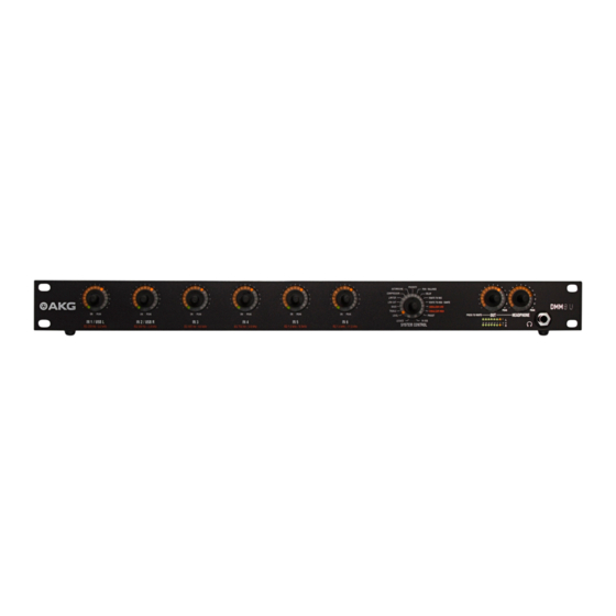
- Page 75 Description Description Summary Summary The DMM8 U (UL, ULD) is a 19" Digital Automatic Microphone Mixer. Internal signal processing takes place digitally. The inputs and outputs are available as analog and digital. It has 6 balanced mono inputs that can be configured as microphone inputs or line inputs (e.g. for wireless microphone receivers). On the output side it has one balanced master output each for the left and right channels, one stereo recording output and one stereo headphone output.
- Page 76 Description Power adapter Power adapter Input voltage 100 ... 240 V AC Mains frequency 50 ... 60 Hz Max. power intake 75 Watt Output voltages 24 V Inputs Balanced inputs – Preamplifier Gain 0 dB ... 60 dB Max. input level +20 dBu Common mode rejection >70 dB...
- Page 77 Description Front controls Front: Description of the controls There is a total of nine controls on the front. PRIORITY AUTOMIXING PAN / BALANCE COMPRESSOR DELAY LIMITER ROUTE TO REC LOW CUT ROUTE TO USB BASS EQUALIZER LOW TREBLE EQUALIZER HIGH ON PEAK ON PEAK ON PEAK...
- Page 78 Description The input sensitivity is modified using the gain regulator on the rear of the connected equipment. SYSTEM 5.3.2 Operating mode / SYSTEM CONTROL CONTROL The DMM8 U (UL, ULD) has numerous functions such as volume, tre- bles, bass, auto-mixer functions etc. These functions are selected on the SYSTEM CONTROL (7). Rotary knobs for 5.3.3 Control for stereo outputs outputs...
- Page 79 Description Rear controls Rear: Description of the controls On the rear are the sockets for the input channels and output channels as well as the mains connection, etc. DANTE IN 1 IN 2 IN 3 IN 4 IN 5 IN 6 OUT L OUT R REC (OUT)
- Page 80 Description Description Mains switch Mains connection Input channels 5.4.1 Inputs IN 1 IN 2 PHANT. PWR Figure 3: Input The 6 balanced input channels (1, 5, 6, 10, 11, 15) can be accessed via 3-pin Phoenix sockets. These are labeled IN 1 to IN 6. The input levels can be controlled with the rotary knobs IN 1 to IN 6 on the front panel.
- Page 81 Description The associated gain control is located next to every input channel (2, 4, 7, 9, 12, 14) to set the input level. The gain controls are equipped with integrated switch for the left side stop. The input level is set at 0 dB when the left end stop is reached By turning the control clockwise the gain can be increased by max.
- Page 82 Description The RS232 socket (21) permits software updates to be carried out and to operate the device via an external control (e.g.: AMX). The pin assignment is as follows: Function USB port 5.4.6 USB port IN - EXPANSION - OUT RS232 Figure 8: USB port The USB port (22) can be used to connect the device to a PC to perform...
- Page 83 Description This web server provides a simple and functional user interface that can be opened via a browser and that permits access via LAN infrastructure. Simultaneous operation via the front panel of the automixer and via the web server is possible: it is preferable for the inputs to be handled via the web server, however.
- Page 84 Description The corresponding slide switch activates the phantom power supply of +48 V for the inputs located on the left and right. Ground connection Figure 12: Phoenix terminal A Phoenix terminal connects the housing to the 0 V potential of the power supply.
- Page 85 Description The linear potentiometer is connected to the VCA input as shown above The resistance at the VCA input is changed by turning the potentiometer This value is input and the volume is changed accordingly The left setting signi- fies 0% while the right setting signifies 100%. The output level depends on the master control and the remote level control.
- Page 86 Description level. The following functions and parameters flow into the automix algo- rithm: • Dynamic level adjustment • Best Mic On • Noise Detect Level adjustment 5.5.1 Dynamic level adjustment The master of all input channels is determined on an ongoing basis. This value is used as the reference value. If the input channel level is very close or over the reference value, this channel will be assessed as dominant and will be slightly attenuated.
- Page 87 Description The device has two 100 MBit/s Ethernet ports. These are used to exchange control data and audio communication between cascaded devices. This means that an automixing system can be realized with: • 60 inputs • 20 outputs • 10 stereo headphone outputs The master buses for OUT, REC-OUT and HEADPHONE are accessible to the entire system of cascaded devices.
- Page 88 instALLAtion AnD connection Installation and connection The following steps are required for installation and connection of the DMM8 U (UL, ULD): Installation Cascade devices (optional) Connecting microphones and accessories Connect to the mains power supply Installation To install the device, proceed as follows: Step Description Mount the device into your 19"...
- Page 89 instALLAtion AnD connection Connect the microphones and accessories to the rear of the DMM8 U (UL, ULD) as follows: Step Description Connect microphones and other signal sources (e.g. receivers for wireless microphones) to the IN inputs Connect outputs OUT L and OUT R to a mixing desk or am- plifier Connect the RCA jacks on the stereo recording output REC (OUT) to a recording device...
- Page 90 fUnctionAL Description Functional description Control concept The device is controlled using the total of 9 rotary knobs on the front panel. These are labeled IN 1 to IN 6, SYSTEM CONTROL, OUT and HEADPHONE. The rotary knobs on the inputs are each surrounded by an LED ring with 15 yellow LEDs, one green LED and one red LED.
- Page 91 fUnctionAL Description 7.2.1 Display of the audio level / VU function With the LEVEL function selected, the level set is displayed on the LED rings on the inputs and outputs. SYSTEM SYSTEM CONTROL CONTROL The SYSTEM CONTROL rotary knob provides the option of selecting various functions on the device.
- Page 92 fUnctionAL Description Other functions given can be selected by pressing individual rotary knobs or combinations of multiple knobs: • Routing To Out • Monitoring • Mute Input channel 7.3.2 Input channel modes modes The input channels have the following function controls: •...
- Page 93 fUnctionAL Description located in the LEVEL mode, regardless of the SYSTEM CONTROL rotary knob setting. DSP functions DSP functions Given below are explanations of the individual functions and their operation and effects. LEVEL 7.4.1 LEVEL PRIORITY AUTOMIXING PAN / BALANCE COMPRESSOR DELAY LIMITER...
- Page 94 fUnctionAL Description The adjustable increments are equal to 1 dB per click from -12 dB to +15 dB. One LED equals 3 dB. The adjustable increments are equal to 3 dB per click from -12 dB to -∞. One LED equals 9 dB. -6 dB -9 dB -3 dB -12 dB 0 dB -21 dB +3 dB...
- Page 95 fUnctionAL Description All inputs and outputs can be controlled in TREBLE mode. 0 dB -2 dB +2 dB -4 dB +4 dB -6 dB +6 dB -8 dB +8 dB -10 dB +10 dB -12 dB +12 dB -14 dB +14 dB ON PEAK TREBLE...
- Page 96 fUnctionAL Description The adjustable increments are equal to 2 dB per click and also correspond to one LED. Figure 22: Adjustment range for the TREBLE function BASS 7.4.3 BASS PRIORITY AUTOMIXING PAN / BALANCE COMPRESSOR DELAY LIMITER ROUTE TO REC LOW CUT ROUTE TO USB BASS...
- Page 97 fUnctionAL Description The BASS raises or lowers the audio signal's bass range. The filter is de- signed as a first order bass shelving filter. The cut-off frequency is 100 Hz. The settings range from -14 dB to +14 dB. Only the upper middle LED lights up (0 dB) with linear adjustment. More LEDs light up on the left side as the rotary knob is turned further to the left.
- Page 98 fUnctionAL Description The adjustable increments are equal to 2 dB per click and also correspond to one LED. Figure 25: Adjustment range for the BASS function LOW CUT 7.4.4 LOW CUT PRIORITY AUTOMIXING PAN / BALANCE COMPRESSOR DELAY LIMITER ROUTE TO REC LOW CUT ROUTE TO USB BASS...
- Page 99 fUnctionAL Description quency can be raised by turning the rotary knob in a clockwise direction and lowered by turning it counter-clockwise. The settings range from 0 Hz (no effect) to 300 Hz (severe attenuation). One LED is illuminated at 0 Hz, while the entire LED ring is illuminated at 300 Hz.
- Page 100 fUnctionAL Description The adjustable increments are equal to 20 Hz per click and also correspond to one LED. Figure 28: Adjustment range for the LOW CUT function LIMITER 7.4.5 LIMITER PRIORITY AUTOMIXING PAN / BALANCE COMPRESSOR DELAY LIMITER ROUTE TO REC LOW CUT ROUTE TO USB BASS...
- Page 101 fUnctionAL Description Turning the rotary knob in a clockwise direction increases the effect, while turning it counterclockwise dampens the effect. The settings range from +20 dBu to -25 dBu. One LED is illuminated at +20 dBu, while the entire LED ring is illuminated at -25 dBu. -4 dBu -1 dBu -7 dBu...
- Page 102 fUnctionAL Description COMPRESSOR 7.4.6 COMPRESSOR PRIORITY AUTOMIXING PAN / BALANCE COMPRESSOR DELAY LIMITER ROUTE TO REC LOW CUT ROUTE TO USB BASS EQUALIZER LOW TREBLE EQUALIZER HIGH LEVEL PRESET LOCKED IN USB / DANTE SYSTEM CONTROL Figure 32: COMPRESSOR function All the input channels can be controlled in the COMPRESSOR mode.
- Page 103 fUnctionAL Description The adjustable increments are equal to 3 dBu per click and also correspond to one LED. +17.5 +12.5 +7.5 +2.5 -2.5 -7.5 -12.5 -17.5 -22.5 -27.5 -32.5 -37.5 Figure 34: Adjustment range for the COMPRESSOR function AUTOMIXING 7.4.7 AUTOMIXING PRIORITY AUTOMIXING...
- Page 104 fUnctionAL Description All the input channels can be controlled in the AUTOMIXING mode. ON PEAK ON PEAK AUTOMIXING Figure 36: Adjustment range for the AUTOMIXING function The automatic mixing functions for the relevant channel are switched on by turning a rotary knob in the clockwise direction. (Entire LED ring is illumi- nated).
- Page 105 fUnctionAL Description The PRIORITY mode allows you to select which input channel will function as the priority channel. The priority channel then receives a 6 dB advantage in the signal detection in connection with the AUTOMIXING mode. ON PEAK ON PEAK PRIORITY Figure 38: Adjustment range for the PRIORITY function The function for the relevant channel is switched on by turning a rotary knob...
- Page 106 fUnctionAL Description all the output channels to be controlled. 0 dB R -6 dB L -6 dB R -12 dB L -12 dB R -18 dB L -18 dB R -24 dB L -24 dB R -30 dB L -30 dB R -36 dB L -36 dB R MIN...
- Page 107 fUnctionAL Description DELAY 7.4.10 DELAY PRIORITY AUTOMIXING PAN / BALANCE COMPRESSOR DELAY LIMITER ROUTE TO REC LOW CUT ROUTE TO USB BASS EQUALIZER LOW TREBLE EQUALIZER HIGH LEVEL PRESET LOCKED IN USB / DANTE SYSTEM CONTROL Figure 41: DELAY function The DELAY function can be used to modify the OUT output.
- Page 108 fUnctionAL Description ROUTING TO 7.4.11 ROUTING TO REC PRIORITY AUTOMIXING PAN / BALANCE COMPRESSOR DELAY LIMITER ROUTE TO REC LOW CUT ROUTE TO USB BASS EQUALIZER LOW TREBLE EQUALIZER HIGH LEVEL PRESET LOCKED IN USB / DANTE SYSTEM CONTROL Figure 43: ROUTING TO REC function All the input channels can be controlled in the ROUTING TO REC mode.
- Page 109 fUnctionAL Description ROUTING TO 7.4.12 ROUTING TO USB PRIORITY AUTOMIXING PAN / BALANCE COMPRESSOR DELAY LIMITER ROUTE TO REC LOW CUT ROUTE TO USB BASS EQUALIZER LOW TREBLE EQUALIZER HIGH LEVEL PRESET LOCKED IN USB / DANTE SYSTEM CONTROL Figure 45: ROUTING TO USB function All the input channels can be controlled in the ROUTING TO USB mode.
- Page 110 fUnctionAL Description EQUALIZER 7.4.13 EQUALIZER PRIORITY AUTOMIXING PAN / BALANCE COMPRESSOR DELAY LIMITER ROUTE TO REC LOW CUT ROUTE TO USB BASS EQUALIZER LOW TREBLE EQUALIZER HIGH LEVEL PRESET LOCKED IN USB / DANTE SYSTEM CONTROL PRIORITY AUTOMIXING PAN / BALANCE COMPRESSOR DELAY LIMITER...
- Page 111 fUnctionAL Description further to the left. More LEDs light up on the right side as the rotary knob is turned further to the right. -6 dB -9 dB -3 dB -12 dB 0 dB -21 dB +3 dB -30 dB +6 dB -39 dB +9 dB...
- Page 112 fUnctionAL Description The center frequencies of the sub-bands are assigned at half-octave intervals. Figure 49: Adjustment range for the EQUALIZER function PRESET 7.4.14 PRESET PRIORITY AUTOMIXING PAN / BALANCE COMPRESSOR DELAY LIMITER ROUTE TO REC LOW CUT ROUTE TO USB BASS EQUALIZER LOW TREBLE...
- Page 113 fUnctionAL Description To do this, the PRESET function is selected on the SYSTEM CONTROL. In addition to the 6 device presets, there is also a work preset: All changes in the settings initially only have an effect on that preset. To store changes permanently, the work preset must be stored under one of the available device presets.
- Page 114 fUnctionAL Description LOCKED LOCKED PRIORITY AUTOMIXING PAN / BALANCE COMPRESSOR DELAY LIMITER ROUTE TO REC LOW CUT ROUTE TO USB BASS EQUALIZER LOW TREBLE EQUALIZER HIGH LEVEL PRESET LOCKED IN USB / DANTE SYSTEM CONTROL Figure 52: LOCKED function In LOCKED mode the rotary knobs or the entire unit are protected against improper use by means of locking.
- Page 115 operAting the Device Operating the device SYSTEM SYSTEM CONTROL: Changing parameters on the device CONTROL To change the parameters on the device, proceed as follows: Step Description Turn to the required function on the SYSTEM CONTROL rotary knob, turning the rotary knob until the LED is lit at the required function.
- Page 116 operAting the Device Step Description Press the slider switch and gain control on the rear of the DMM8 U (UL, ULD) • Select the amplification of the input signals between 0 dB and +57 dB. • Higher amplification of the input signals is suitable for microphones with a low output level. • Lower amplification is recommended for microphones with a high output level. •...
- Page 117 operAting the Device Cascading devices Caution: Risk of damage It is only permitted for this connection to be carried out by authorized, qual- ified personnel. It is not permitted to connect the first device in the cascade to the last device. To cable the individual devices with the expansion sockets, proceed as follows: Step Description Cascade the devices as follows using CAT5+ connection cables: OUT R...
- Page 118 operAting the Device Step Description Press the SYSTEM CONTROL rotary knob twice briefly (dou- ble-click) • The 6 input controls are switched over for operation. The LEDs IN USB and IN USB/DANTE are permanently lit • • Changes to the input controls no longer affect the 6 analog inputs;...
- Page 119 operAting the Device Step Description With SYSTEM CONTROL, select the PRESET function Briefly press the rotary knob for the corresponding input or output. • An acoustic signal (beep) is sounded. Release the rotary knob after the beep • Device preset is loaded to work preset. • Settings for the selected device preset are active immedi- ately (all LEDs lit).
- Page 120 operAting the Device Step Description Press the rotary knob for the corresponding input or output for between 8 and 10 seconds • An acoustic signal (beep) is sounded. Release the rotary knob after the beep • The device preset is deleted and cannot be selected (emp- ty storage location, LED 1 lit).
- Page 121 operAting the Device Step Description Briefly press the rotary knob for the corresponding input or output. MUTE function for the corresponding channel is deactivat- • • The volume previously stored is applied. ROUTING TO Activating ROUTING TO OUT 8.9.1 For an input All inputs can be routed to the OUT output. Proceed as follows: Step Description Press and hold the OUT rotary knob...
- Page 122 operAting the Device Step Description Press the rotary knob of the required input ROUTING TO OUT is deactivated for the corresponding • input. LOCKED 8.11 Activate/deactivate LOCKED The following elements can be locked using the LOCKED function: SYSTEM CONTROL rotary knob •...
- Page 123 operAting the Device Lock unit 8.11.3 Locking the complete unit To lock the complete unit, proceed as follows: Step Description Press the SYSTEM CONTROL rotary knob at the same time as the OUT rotary knob for longer than 3 seconds The LOCKED LED is lit.
- Page 124 operAting the Device Step Description Lock the complete unit, to do this press the SYSTEM CONTROL rotary knob at the same time as the OUT rotary knob for longer than 3 seconds The LOCKED LED is lit. • • The original settings are stored. •...
- Page 125 operAting the Device 8.12 Copying configuration data The copy function can be used to copy individual or multiple settings (LEVEL, TREBLE, BASS, LOWCUT, LIMITER and COMPRESSOR) on an input to one or more other inputs. Copy 8.12.1 Copying individual values configurations To copy individual values from one channel to one or more other channels, proceed as follows:...
- Page 126 operAting the Device Step Description Keep both rotary knobs pressed down (approx. 8 seconds) until an acoustic signal is sounded (beep beep) and the affect- ed LED rings flash once briefly. • Values were transmitted to the selected channels. The copy process is possible in both directions (IN 1 to IN 6 and IN 6 to IN 1).
- Page 127 operAting the Device ON PEAK ON PEAK ON PEAK ON PEAK ON PEAK ON PEAK IN 1 IN 2 IN 3 IN 4 IN 5 IN 6 Figure 56: Complete copy process Reset to factory 8.13 Resetting the factory settings settings To reset the factory settings for the entire device, proceed as follows: Step...
- Page 128 operAting the Device PRIORITY AUTOMIXING PAN / BALANCE COMPRESSOR DELAY LIMITER ROUTE TO REC LOW CUT ROUTE TO USB BASS EQUALIZER LOW TREBLE EQUALIZER HIGH LEVEL PRESET LOCKED IN USB / DANTE SYSTEM CONTROL Figure 57: Resetting the factory settings Resetting the factory settings deletes all of the stored settings! DMM8 MANUAL...
- Page 129 troUbLeshooting Troubleshooting WARNING: Risk of electric shock There are unprotected contacts and cables within the unit that could cause serious injury from electric shock on contact. • The unit is only permitted to be opened by authorized, qualified personnel for troubleshooting purposes. PROBLEM POSSIBLE CAUSE REMEDY No sound Power supply cable is not connected Connect power supply cable to unit to unit Power switch off...
- Page 130 troUbLeshooting PROBLEM POSSIBLE CAUSE REMEDY Distorted signal repro- Pre-amplification not set correctly Set gain control on rear panel to cor- duction rect pre-amplification Volume control turned up too far Turn down volume Input signal level too high Reduce input signal If the error persists despite these instructions, contact AKG Acoustics GmbH or your AKG dealer immediate- DMM8 MANUAL...
- Page 131 DMM8 MANUAL...
- Page 132 INHALT GÉNÉRALITÉS 5.4.2 Régulateur de gain Objectif de ce document 5.4.3 Canal de sortie de somme stéréo Conservation de ce document 5.4.4 Sortie Enregistrement stéréo Responsabilité 5.4.5 Commande sérielle (RS232) Garantie 5.4.6 Prise USB 5.4.7 Prise LAN LIVRAISON 5.4.8 Mise en cascade de systèmes Contenu de l'emballage 5.4.9 Alimentation fantôme...
-
Page 133: Table Of Contents
INHALT 7.4.1 LEVEL 8.7 Utiliser les profils 7.4.2 TREBLE 8.7.1 Sélectionner un profil 7.4.3 BASS 8.7.2 Programmer un profil 7.4.4 LOW CUT 8.7.3 Supprimer un profil 7.4.5 LIMITER Utiliser MUTE 7.4.6 COMPRESSOR 8.8.1 Activer MUTE 7.4.7 AUTOMIXING 8.8.2 Désactiver MUTE 7.4.8 PRIORITY Activer ROUTING TO OUT 7.4.9 PAN / BALANCE 8.9.1 Pour un canal d'entrée 7.4.10... - Page 134 Tél : +43 (0)1 86654-0 Tél : +1 818 920-3224 Fax : +43 (0)1 86654-8800 sales@akg.com akgusatechsupport@harman.com Copyright © 2015 AKG Acoustics GmbH Tous droits réservés. Les informations de ce mode d'emploi, les schémas, et les photos annexes sont la propriété...
- Page 135 générALités Généralités Objectif de ce document Cette documentation est destinée à vous permettre : • de manipuler ce système en toute sécurité • d'utiliser ce système de façon conforme. Conservation de ce document Imprimez ce mode d'emploi et conservez.le précautionneusement ou enre- gistrez-le électroniquement sur un support facile d'accès.
- Page 136 LivrAison Livraison Contenu de Contenu de l'emballage l'emballage Contrôlez l'exhaustivité de la livraison. Adressez-vous à votre fournisseur AKG si elle est incomplète. • 1 DMM8 U, DMM8 UL ou DMM8 ULD • 1 Guide rapide • 1 câble d'alimentation CEI EU standard •...
- Page 137 sécUrité et environnement Sécurité et environnement Sécurité Sécurité Attention : Risque d'endommagement • Protégez votre système de l'ensoleillement direct de la poussière et de l'humidité de la pluie des vibrations et des coups. • Ne renversez pas de liquide sur le système et ne laissez rien tomber dans les fentes d'aération.
- Page 138 sécUrité et environnement • Pour éviter les pannes et perturbations électriques, séparez les câbles, en particulier ceux des entrées de microphone des câbles à courant fort et d'alimentation réseau. Si vous effectuez le câblage en gaines ou en canaux à câbles, placez les câbles de transmission dans un canal séparé.
- Page 139 DécLArAtion De conformité Indique des informations et des téléchargements Internet complémentaires. Indique des informations relatives à l'élimination correcte des composants décrits. Utilisation conforme Le mixeur de microphone numérique automatique DMM8 U (UL, ULD) est réservé au mixage de signaux audio. Utilisation non conforme Toute utilisation autre que l'utilisation ci-dessus sera considéré...
- Page 140 Description DU système Description du système Description Description abrégée abrégée Le DMM8 U (UL, ULD) est un mixeur de microphone numérique automatique 19". Le traitement des signaux interne est numérique. Les entrées et sorties sont disponibles en version analogique ou numérique. Le système est doté...
- Page 141 Description DU système Module Module d'alimentation d'alimentation Tension d'entrée 100 ... 240 V AC Fréquence de réseau 50 ... 60 Hz Consommation max. 75 Watt Tensions de sortie 24 V Entrées Entrées symétriques - Préampli Gain 0 dB ... 60 dB Niveau d'entrée max.
- Page 142 Description DU système Sorties Enregistrement et Sortie de somme Fréquence d'échantillonnage 48 kHz Contrôles Face Face avant : Description des contrôles avant Neuf régulateurs rotatifs sont placés sur la face avant. PRIORITY AUTOMIXING PAN / BALANCE COMPRESSOR DELAY LIMITER ROUTE TO REC LOW CUT ROUTE TO USB BASS...
- Page 143 Description DU système LED ON ON s'allume si le canal d'entrée a la priorité en mode Automatique. Si cette fonction Automix est désactivée, ON est toujours allumé. LED PEAK PEAK s'allume, lorsque le signal au niveau d'un canal d'entrée se rapproche du seuil de contrôle maximal.
- Page 144 Description DU système Contrôles Face Face arrière : Description des contrôles arrière La face arrière contient les prises d'alimentation, des canaux d'entrée et des canaux de sortie. DANTE IN 1 IN 2 IN 3 IN 4 IN 5 IN 6 OUT L OUT R REC (OUT)
- Page 145 Description DU système N° Description Interrupteur réseau Raccord réseau Canaux d'entrée 5.4.1 Canaux d'entrée IN 1 IN 2 PHANT. PWR Illustration 3 : Canal d'entrée Les 6 canaux d'entrée symétriques (1, 5, 6, 10, 11, 15) sont accessibles par douilles tripolaires XLR. Elle sont repérées de IN 1 à IN 6. Les régulateurs rotatifs IN 1 à...
- Page 146 Description DU système Chaque canal d'entrée est doté à son côté d'un régulateur de gain (2, 4, 7, 9, 12, 14) pour ajuster le niveau d'entrée. Les régulateurs de gain sont munis d'un interrupteur en butée gauche. Le niveau d'entrée est de 0 dB en butée gauche. Il peut être amené à son maximum de 57 dB en tournant le régulateur vers la droite.
- Page 147 Description DU système Commande 5.4.5 Commande sérielle (RS232) sérielle RS232 Illustration 7 : Commande sérielle La prise RS232 (21) permet d'effectuer les mises à jour du logiciel et de contrôler le système avec une commande externe (p.ex. : AMX). Affectation des broches : Broche Fonction...
- Page 148 Description DU système Prise LAN 5.4.7 Prise LAN IN - EXPANSION - OUT RS232 Illustration 9 : Prise LAN La prise LAN (23) permet d'effectuer les mises à jour du logiciel et de contrôler le système avec une commande externe (p.ex. : AMX). Elle assure aussi la liaison pour la commande et le diagnostic à...
- Page 149 Description DU système La transmission audio en cascade se fait en 24 bits. Les bruits n'en sont pas aggravés. Alimentation 5.4.9 Alimentation fantôme fantôme IN 1 IN 2 PHANT. PWR Illustration 11 : Alimentation fantôme Le système est doté de trois interrupteurs d'alimentation fantôme (3, 8, 13). L'interrupteur coulissant active la tension d'alimentation fantôme de +48 V pour les entrées à...
- Page 150 Description DU système Commande analogique Illustration 13 : Borne Phoenix Un potentiomètre linéaire 50 kΩ peut être installé à l'entrée V AC du volume général. Poti 50k lin. Illustration 14 : V AC Le potentiomètre linéaire est branché à l'entrée V AC comme illustré ci-des- sus. Tournez le potentiomètre pour modifier la résistance à l'entrée V AC.
- Page 151 Description DU système Tous les canaux de sortie et d'entrée seront alors automatiquement routés vers le réseau Dante™. Après traitement du signal (basses, aiguës, ...) et l'algorithme Automix, les canaux d'entrée sont routés vers le réseau Dante™ sous forme de signaux Direct-Out.
- Page 152 Description DU système maintenir leur somme du niveau de sortie. L'augmentation d'un canal dure en général entre 3 et 5 ms. Best Mic On 5.5.2 Best Mic On La proximité de deux microphones a pour conséquence négative la géné- ration d'effets de peigne par suppression de fréquences. Pour éviter ces signaux étouffés ou creux, seul le canal du microphone ayant le niveau le plus élevé...
- Page 153 montAge et rAccorDement Montage et raccordement Étapes du montage et du raccordement du DMM8 U (UL, ULD) : Montage Mettre les systèmes en cascade (option) Brancher les microphones et instruments Brancher le système sur le courant Montage Montage du système : Étape Description Fixez le système dans le rack 19"...
- Page 154 montAge et rAccorDement Étape Description Branchez les microphones et les autres sources de signaux (le récepteur d'un microphone sans fil, par ex.) au canaux d'entrée IN Connectez les canaux de sortie OUT L et OUT R à une table de mixage ou un amplificateur Connectez les douilles Cinch de la sortie Enregistrement sté- réo REC (OUT) à...
- Page 155 Description DU fonctionnement Description du fonctionnement Manipulation Le système est manipulé au travers des 9 régulateurs rotatifs placés sur sa face avant. Ils sont repérés ainsi : IN 1 à IN 6, SYSTEM CONTROL, OUT et HEADPHONE. Les régulateurs rotatifs des entrées sont entourés d'une DEL verte, d'une rouge et d'une couronne de 15 DEL jaunes.
- Page 156 Description DU fonctionnement 7.2.1 Affichage du niveau audio et de la fonction VU Lorsque la fonction LEVEL est sélectionnée, les couronnes DEL des entrées et sorties affichent le niveau réglé. SYSTEM SYSTEM CONTROL CONTROL Le régulateur rotatif SYSTEM CONTROL sert à sélectionner différentes fonctions du système. PRIORITY AUTOMIXING PAN / BALANCE...
- Page 157 Description DU fonctionnement Appuyez sur les autres régulateurs rotatifs, seuls ou en combinaison, pour sélectionner les fonctions suivantes : • Routing To Out • Contrôle • Mute Fonctions des 7.3.2 Fonctions des canaux d'entrée canaux d'entrée Les canaux d'entrée sont modifiés par les fonctions suivantes : • Level • Treble •...
-
Page 158: Level
Description DU fonctionnement Fonctions DSP Fonctions DSP Manipulation et fonctionnement des fonctions : LEVEL 7.4.1 LEVEL PRIORITY AUTOMIXING PAN / BALANCE COMPRESSOR DELAY LIMITER ROUTE TO REC LOW CUT ROUTE TO USB BASS EQUALIZER LOW TREBLE EQUALIZER HIGH LEVEL PRESET LOCKED IN USB / DANTE SYSTEM CONTROL... -
Page 159: Treble
Description DU fonctionnement Pour faciliter la visualisation de la position 0 dB, sa DEL (n° 10) est plus claire que les autres. Attention, ce niveau 0 dB n'est atteint que lorsque le troisième cran est atteint après allumage de la DEL (voir Détail LEVEL). Appuyez sur le régulateur rotatif SYSTEM CONTROL en fonction LEVEL pour basculer l'affichage des canaux d'entrée et de sortie d'Amplification à... -
Page 160: Bass
Description DU fonctionnement Si vous tournez le régulateur rotatif vers la droite, les DEL de gauche s'allu- ment en conséquence. Le pas, réglable, est de 2 dB par cran et correspond à l'allumage d'une DEL. Illustration 22 : Paramètres de la fonction TREBLE BASS 7.4.3 BASS... - Page 161 Description DU fonctionnement La fonction BASSE sert à régler les basses du signal audio. Le filtre est de type Shelving Low (plateau bas) de niveau 1. Le seuil de fréquence est 100 Plage de réglage : -14 à +14 dB. En mode Linéaire, seule la DEL du milieu (0 dB) s'allume. Si vous tournez le régulateur rotatif vers la gauche, les DEL de gauche s'allument en conséquence.
-
Page 162: Low Cut
Description DU fonctionnement Le pas, réglable, est de 2 dB par cran et correspond à l'allumage d'une DEL. Illustration 25 : Paramètres de la fonction BASS LOW CUT 7.4.4 LOW CUT PRIORITY AUTOMIXING PAN / BALANCE COMPRESSOR DELAY LIMITER ROUTE TO REC LOW CUT ROUTE TO USB BASS... - Page 163 Description DU fonctionnement Plage de réglage : 0 Hz (aucun effet) à 300 Hz (atténuation forte) À 0 Hz, une DEL est allumée. À 300 Hz, la couronne de DEL est complète. 160 Hz 140 Hz 180 Hz 120 Hz 200 Hz 100 Hz 220 Hz...
-
Page 164: Limiter
Description DU fonctionnement LIMITER 7.4.5 LIMITER PRIORITY AUTOMIXING PAN / BALANCE COMPRESSOR DELAY LIMITER ROUTE TO REC LOW CUT ROUTE TO USB BASS EQUALIZER LOW TREBLE EQUALIZER HIGH LEVEL PRESET LOCKED IN USB / DANTE SYSTEM CONTROL Illustration 29 : Fonction LIMITER La fonction LIMITER s'applique à... -
Page 165: Compressor
Description DU fonctionnement Le pas, réglable, est de 3 dB par cran et correspond à l'allumage d'une DEL. Illustration 31 : Paramètres de la fonction LIMITER COMPRESSOR 7.4.6 COMPRESSOR PRIORITY AUTOMIXING PAN / BALANCE COMPRESSOR DELAY LIMITER ROUTE TO REC LOW CUT ROUTE TO USB BASS... - Page 166 Description DU fonctionnement Plage de réglage : +20 à -25 dBu. À +20 dBu, une DEL est allumée. À -25 dBu, la couronne de DEL est complète. -4 dBu -1 dBu -7 dBu +2 dBu -10 dBu -13 dBu +5 dBu +8 dBu -16 dBu +11 dBu...
-
Page 167: Automixing
Description DU fonctionnement AUTOMIXING 7.4.7 AUTOMIXING PRIORITY AUTOMIXING PAN / BALANCE COMPRESSOR DELAY LIMITER ROUTE TO REC LOW CUT ROUTE TO USB BASS EQUALIZER LOW TREBLE EQUALIZER HIGH LEVEL PRESET LOCKED IN USB / DANTE SYSTEM CONTROL Illustration 35 : Fonction AUTOMIXING La fonction AUTOMIXING s'applique à... -
Page 168: Priority
Description DU fonctionnement PRIORITY 7.4.8 PRIORITY PRIORITY AUTOMIXING PAN / BALANCE COMPRESSOR DELAY LIMITER ROUTE TO REC LOW CUT ROUTE TO USB BASS EQUALIZER LOW TREBLE EQUALIZER HIGH LEVEL PRESET LOCKED IN USB / DANTE SYSTEM CONTROL Illustration 37 : Fonction PRIORITY Cette fonction ne peut être activée que sur un seul canal d'entrée. -
Page 169: Pan / Balance
Description DU fonctionnement PAN / BALANCE 7.4.9 PAN / BALANCE PRIORITY AUTOMIXING PAN / BALANCE COMPRESSOR DELAY LIMITER ROUTE TO REC LOW CUT ROUTE TO USB BASS EQUALIZER LOW TREBLE EQUALIZER HIGH LEVEL PRESET LOCKED IN USB / DANTE SYSTEM CONTROL Illustration 39 : Fonction PAN / BALANCE La fonction PAN / BALANCE s'applique à... -
Page 170: Delay
Description DU fonctionnement tournez le régulateur rotatif de cette entrée vers la gauche, avec la fonction PAN activée. Le pas, réglable, est de 6 dB par cran et correspond à l'allumage d'une DEL. DELAY 7.4.10 DELAY PRIORITY AUTOMIXING PAN / BALANCE COMPRESSOR DELAY LIMITER... -
Page 171: Routing To Rec
Description DU fonctionnement ROUTING TO REC 7.4.11 ROUTING TO REC PRIORITY AUTOMIXING PAN / BALANCE COMPRESSOR DELAY LIMITER ROUTE TO REC LOW CUT ROUTE TO USB BASS EQUALIZER LOW TREBLE EQUALIZER HIGH LEVEL PRESET LOCKED IN USB / DANTE SYSTEM CONTROL Illustration 43 : Fonction ROUTING TO REC La fonction ROUTING TO REC s'applique à... -
Page 172: Routing To Usb
Description DU fonctionnement ROUTING TO USB 7.4.12 ROUTING TO USB PRIORITY AUTOMIXING PAN / BALANCE COMPRESSOR DELAY LIMITER ROUTE TO REC LOW CUT ROUTE TO USB BASS EQUALIZER LOW TREBLE EQUALIZER HIGH LEVEL PRESET LOCKED IN USB / DANTE SYSTEM CONTROL Illustration 45 : Fonction ROUTING TO USB La fonction ROUTING TO USB s'applique à... -
Page 173: Equalizer
Description DU fonctionnement EQUALIZER 7.4.13 EQUALIZER PRIORITY AUTOMIXING PAN / BALANCE COMPRESSOR DELAY LIMITER ROUTE TO REC LOW CUT ROUTE TO USB BASS EQUALIZER LOW TREBLE EQUALIZER HIGH LEVEL PRESET LOCKED IN USB / DANTE SYSTEM CONTROL PRIORITY AUTOMIXING PAN / BALANCE COMPRESSOR DELAY LIMITER... - Page 174 Description DU fonctionnement les DEL de gauche en conséquence. Tourner le régulateur vers la droite fait s'allumer les DEL de droite en conséquence. -6 dB -9 dB -3 dB -12 dB 0 dB -21 dB +3 dB -30 dB +6 dB -39 dB +9 dB -48 dB...
-
Page 175: Preset
Description DU fonctionnement PRESET 7.4.14 PRESET PRIORITY AUTOMIXING PAN / BALANCE COMPRESSOR DELAY LIMITER ROUTE TO REC LOW CUT ROUTE TO USB BASS EQUALIZER LOW TREBLE EQUALIZER HIGH LEVEL PRESET LOCKED IN USB / DANTE SYSTEM CONTROL Illustration 50 : Fonction PRESET Vous pouvez définir, enregistrer et charger dans le système jusqu'à 6 profils de système différents (LEVEL, TREBLE, BASS, …... -
Page 176: Locked
Description DU fonctionnement Si toutes les DEL de la couronne et la DEL rouge PEAKsont allumées, l'es- pace est occupé et sélectionnée (voir Illustration 51, générateurs d'incré- ments IN 1 / USB L). Si seule la DEL 1 de la couronne et la DEL rouge PEAKsont allumées, l'espace est occupé... -
Page 177: Manipulation Du Système
mAnipULAtion DU système Manipulation du système SYSTEM SYSTEM CONTROL : Modifier les paramètres du système CONTROL Modification des paramètres du système : Étape Description Sélectionnez la fonction en tournant le régulateur rotatif SYSTEM CONTROL jusqu'à ce que la DEL de la fonction choisie s'allume Réglez la fonction au niveau des canaux d'entrée avec les régulateurs rotatifs IN 1 à... -
Page 178: Écouter Les Entrées Et Sorties
mAnipULAtion DU système Étape Description Réglez l'interrupteur coulissant et le régulateur de gain sur la face arrière du DMM8 U (UL, ULD) • Plage de réglage : 0 à +57 dB. • L'augmentation de l'amplification du signal d'entrée est adaptée aux microphones avec un niveau de sortie faible. •... -
Page 179: Mettre Les Systèmes En Cascade
mAnipULAtion DU système La sortie REC (OUT)ne peut être écoutée. Mettre les systèmes en cascade Attention : Risque d'endommagement Le raccordement est réservé au spécialistes autorisés. Ne raccordez pas le premier système de la cascade au dernier. Câblage des systèmes avec les douilles d'extension : Étape Description Réunissez comme suit les systèmes avec le câble de... -
Page 180: Activer L'alimentation Fantôme
mAnipULAtion DU système Étape Description Appuyez deux fois rapidement sur le régulateur rotatif SYSTEM CONTROL (clic double) • Les 6 régulateurs d'entrée sont commutés sur manipula- tion. Les DEL IN USB ou IN USB/DANTE s'allument en continu. • • Les modifications effectuées sur les régulateurs d'entrée ne s'appliquent plus aux 6 entrées analogiques, mais aux entrées numériques 7 à... -
Page 181: Programmer Un Profil
mAnipULAtion DU système Étape Description Sélectionnez, sur SYSTEM CONTROL, la fonction PRESET Appuyez un court instant sur le régulateur rotatif du canal d'entrée ou de sortie correspondant • Un signal acoustique (bip) retentit. Relâchez le régulateur rotatif après le bip. •... -
Page 182: Utiliser Mute
mAnipULAtion DU système Étape Description Appuyez entre 8 et 10 secondes sur le régulateur rotatif du canal d'entrée ou de sortie correspondant • Un signal acoustique (bip) retentit. Relâchez le régulateur rotatif après le bip. • Le profil du système est supprimé et ne peut plus être sélectionné (espace de stockage vide, DEL 1 s'allume). MUTE Utiliser MUTE 8.8.1... -
Page 183: Activer Routing To Out
mAnipULAtion DU système Étape Description Appuyez un court instant sur le régulateur rotatif du canal d'entrée ou de sortie correspondant La fonction MUTE du canal correspondant est désacti- • vée. • Le volume enregistré avant MUTE est utilisé. ROUTING TO OUT Activer ROUTING TO OUT 8.9.1 Pour un canal d'entrée... -
Page 184: Activer/Désactiver Locked
mAnipULAtion DU système Étape Description Appuyez sur le régulateur rotatif du canal d'entrée choisi. ROUTING TO OUT est désactivé pour le canal d'entrée • correspondant. LOCKED 8.11 Activer/Désactiver LOCKED La fonction LOCKED sert à verrouiller les éléments suivants : Régulateur rotatif SYSTEM CONTROL •... -
Page 185: 8.11.3 Verrouiller Le Système
mAnipULAtion DU système Verrouiller le 8.11.3 Verrouiller le système système Verrouillage du système : Étape Description Appuyez plus de 3 secondes sur les régulateurs rotatifs SYSTEM CONTROL et OUT La DEL LOCKED s'allume. • • Les réglages sont enregistrés. • Tourner le régulateur rotatif n'a plus aucun effet. -
Page 186: 8.11.6 Verrouiller Certains Canaux
mAnipULAtion DU système Étape Description Verrouillez le système en appuyant plus de 3 secondes sur les régulateurs rotatifs SYSTEM CONTROL et OUT La DEL LOCKED s'allume. • • Les réglages sont enregistrés. • Tourner le régulateur rotatif n'a plus aucun effet. Tous les autres régulateurs rotatifs sont sur LEVEL et •... -
Page 187: Copier Des Données De Configuration
mAnipULAtion DU système 8.12 Copier des données de configuration La fonction de copie sert à dupliquer vers une ou plusieurs autres en- trées les réglages (LEVEL, TREBLE, BASS, LOWCUT, LIMITER et COMPRESSOR) d'une entrée. Copier des 8.12.1 Copier des valeurs configurations Copie d'une valeur d'un canal vers un ou plusieurs autres canaux. -
Page 188: Réinitialiser À La Configuration D'usine
mAnipULAtion DU système Les illustrations suivantes vous aident à visualiser la copie. ON PEAK ON PEAK ON PEAK ON PEAK ON PEAK ON PEAK IN 1 IN 2 IN 3 IN 4 IN 5 IN 6 Illustration 53 : Sélectionner le régulateur rotatif (source) ON PEAK ON PEAK ON PEAK... - Page 189 mAnipULAtion DU système Étape Description Allumez le système Attendez que sa séquence de démarrage soit terminée (env. 15 secondes) Appuyez sur le régulateur rotatif SYSTEM CONTROL sans le relâcher jusqu'à l'étape 5 Éteignez le système avec l'interrupteur Rallumez-le après un court instant Attendez que sa séquence de démarrage soit terminée (env.
-
Page 190: Résolution Des Erreurs
résoLUtion Des erreUrs Résolution des erreurs ATTENTION : Risque de choc électrique Le système contient des contacts et câbles électriques non protégés. Les toucher peut entraîner un choc électrique responsable de blessures graves. • Le système ne peut être ouvert pour réparation que par des profes- sionnels autorisés. - Page 191 résoLUtion Des erreUrs ERREUR ORIGINE POSSIBLE SOLUTION Distorsion des si- Le préampli n'est pas réglé correcte- Rétablissez la bonne configuration du gnaux ment. régulateur de gain sur la face arrière d système Les régulateurs rotatifs de volume sont Diminuez le volume trop forts Le niveau du signal d'entrée est trop Atténuez le signal d'entrée haut Si une erreur persiste malgré...
- Page 192 DMM8 MANUAL...
- Page 193 DMM8 MANUAL...
- Page 194 INHALT GENERALIDADES 5.3.5 Salida estéreo para auriculares Objeto del manual Parte posterior: Descripción de los Conservación del manual controles Responsabilidad 5.4.1 Canales de entrada Garantía 5.4.2 Controles de ganancia 5.4.3 Canal de salida compuesto estéreo VOLUMEN DE SUMINISTRO 5.4.4 Salida de grabación estéreo Contenido del embalaje 5.4.5 Control serie mediante RS232...
- Page 195 INHALT 7.3.4 Funciones de la salida estéreo Activación de la alimentación para auriculares (salida para fantasma monitorización) Empleo de programas Funciones DSP 8.7.1 Selección de programas 7.4.1 LEVEL 8.7.2 Programación de programas 7.4.2 TREBLE 8.7.3 Eliminación de programas 7.4.3 BASS Empleo de MUTE 7.4.4 LOW CUT...
- Page 196 U.S.A. Tfno.: +43 (0)1 86654-0 Tfno.: +1 818 920-3224 Fax: +43 (0)1 86654-8800 sales@akg.com akgusatechsupport@harman.com Copyright © 2015 AKG Acoustics GmbH Todos los derechos reservados. La información contenida en este manual de instrucciones, así como los dibujos y fotografías adjuntos, son propiedad intelectual de AKG Acoustics GmbH.
-
Page 197: Generalidades
generALiDADes Generalidades Objeto del manual El presente manual tiene por objeto capacitar al usuario para • manejar el equipo de modo seguro • y emplearlo conforme al uso previsto. Conservación del manual Imprima este manual y consérvelo cuidadosamente o guárdelo en formato electrónico en un lugar de fácil acceso. -
Page 198: Volumen De Suministro
voLUmen De sUministro Volumen de suministro Contenido del Contenido del embalaje embalaje Compruebe que el embalaje contenga todas las piezas descritas a conti- nuación. Si faltase algo, póngase en contacto con su distribuidor de AKG. • 1 x DMM8 U, DMM8 UL o DMM8 ULD •... -
Page 199: Seguridad Y Medio Ambiente
segUriDAD y meDio Ambiente Seguridad y medio ambiente Seguridad Seguridad Atención: Peligro de desperfectos • Proteja el equipo frente a la radiación solar directa, el polvo y la humedad intensos, la lluvia y vibraciones o impactos. • No derrame líquidos sobre el equipo ni permita que penetre ningún otro objeto en el mismo a través de las rendijas de ventilación. -
Page 200: Conocimientos Requeridos Y
segUriDAD y meDio Ambiente • Para evitar perturbaciones o interferencias, tienda todos los cables, y particularmente los de las entradas de micrófonos, separados de los cables de alimentación y de red. Si tiende los cables en conduc- tos o canales para cables, coloque los cables de transmisión en un canal separado. -
Page 201: Uso Previsto
DecLArAción De conformiDAD Contiene referencias a información adicional y descar- gas de Internet. Aporta información relativa a una eliminación adecuada de los componentes descritos. Uso previsto El mezclador automático digital de micrófonos DMM8 U (UL, ULD) está diseñado exclusivamente para mezclar señales de audio. Uso indebido Se considerará... -
Page 202: Descripción Del Equipo
Descripción DeL eqUipo Descripción del equipo Descripción Descripción breve breve El DMM8 U (UL, ULD) es un mezclador de micrófonos digital automático de 19". El procesamiento interno de señales se efectúa de modo digital. Dispone de entradas y salidas tanto analógicas como digitales. El equipo dispone de 6 canales de entrada mono balanceados que pue- den configurarse como entradas de micrófono o entradas de línea (p. ej., para receptores de micrófonos inalámbricos). - Page 203 Descripción DeL eqUipo Adaptador de Adaptador de corriente corriente Tensión de entrada 100 ... 240 V CA Frecuencia de red 50 ... 60 Hz Consumo de potencia máx. 75 W Tensiones de salida 24 V Entradas Entradas balanceadas – Preamplificador Ganancia 0 dB ...
-
Page 204: Parte Frontal: Descripción De Los Controles
Descripción DeL eqUipo Salidas Salida de grabación y compuesta Formato de datos 24 bits Frecuencia de muestreo 48 kHz Controles Parte frontal: Descripción de los controles delanteros En la parte frontal se encuentran un total de nueve controles giratorios. PRIORITY AUTOMIXING PAN / BALANCE COMPRESSOR... -
Page 205: Control / System Control
Descripción DeL eqUipo LED ON El LED de ON se ilumina cuando se ha concedido prioridad al modo auto- mático del canal de entrada en cuestión. Si la función de mezcla automática se encuentra desactivada, el LED ON se iluminará de modo continuo. LED PEAK El LED PEAK se ilumina cuando la señal de un canal de entrada se aproxi- ma al límite máximo de modulación. -
Page 206: Parte Posterior: Descripción De Los Controles
Descripción DeL eqUipo Controles Parte posterior: Descripción de los controles traseros En la parte posterior se encuentran, entre otros elementos, las tomas de los canales de entrada y de salida, así como la conexión a red. DANTE IN 1 IN 2 IN 3 IN 4 IN 5... -
Page 207: Canales De Entrada
Descripción DeL eqUipo N.º Descripción Interruptor de red Conexión a red Canales de 5.4.1 Canales de entrada entrada IN 1 IN 2 PHANT. PWR Figura 3: Canal de entrada Los 6 canales de entrada balanceados (1, 5, 6, 10, 11, 15) se encuentran accesibles mediante conectores hembra XLR de 3 polos. -
Page 208: Controles De Ganancia
Descripción DeL eqUipo Controles de 5.4.2 Controles de ganancia ganancia IN 1 IN 2 0 dB 0 dB 57 dB 57 dB PHANT. PWR Figura 4: Controles de ganancia Junto a cada canal de entrada se encuentra su control de ganancia corres- pondiente (2, 4, 7, 9, 12, 14), con el que se controla su nivel de entrada. -
Page 209: Salida De Grabación Estéreo
Descripción DeL eqUipo Salida estéreo 5.4.4 Salida de grabación estéreo para grabación REC (OUT) Figura 6: Salida de grabación estéreo Para conectar un dispositivo de grabación estéreo, el equipo dispone de dos conectores RCA hembra marcados con la leyenda REC (OUT) (18). La asignación de canales concretos a la salida de grabación estéreo desbalan- ceada puede configurarse libremente. -
Page 210: Conexión Usb
Descripción DeL eqUipo Conexión USB 5.4.6 Conexión USB IN - EXPANSION - OUT RS232 Figura 8: Conexión USB La conexión USB (22) permite conectar el equipo a un ordenador para reali- zar actualizaciones de firmware y posibilitar el control externo. La conexión se realiza mediante controladores estándar de Windows. En caso necesario, deberá... -
Page 211: Conexión De Equipos En Cascada
Descripción DeL eqUipo En función del tipo y del alcance de la programación, estas aplicaciones pueden proporcionar bastantes más funciones y, en consecuencia, una superficie gráfica más compleja a sus terminales. Conexión en 5.4.8 Conexión de equipos en cascada cascada OUT R REC (OUT) IN - EXPANSION - OUT RS232 Figura 10: Expansión Mediante los jack modulares hembra de 8 polos (RJ-45) (20) es posible... - Page 212 Descripción DeL eqUipo Conexión a tierra/ground Figura 12: Borne Phoenix Un borne Phoenix permite conectar la carcasa al potencial de 0 V del sumi- nistro de tensión. Sólo puentee el potencial 0 V con la conexión a tierra (ajuste de fábrica) o con el sistema central de puesta a tierra, ya que de lo contrario la alimenta- ción fantasma no tendrá...
-
Page 213: Red Dante
Descripción DeL eqUipo temente. La posición izquierda se corresponde con el 0%, mientras que la derecha se corresponde con el 100%. El nivel de salida depende del sistema control de señales compuestas y del control remoto de nivel. El control remoto de nivel afecta a ambas señales compuestas en igual medida. -
Page 214: Algoritmo De Mezcla Automática
Descripción DeL eqUipo Algoritmo Algoritmo de mezcla automática de mezcla automática El algoritmo de mezcla automática del equipo incluye 3 funciones básicas que le permiten determinar en qué valor atenuar una señal de entrada y qué nivel de salida tendrá la señal de salida. El algoritmo de mezcla automática tiene en cuenta las siguientes funciones y parámetros: •... -
Page 215: Conexión De Equipos En Cascada
Descripción DeL eqUipo Expansión para Conexión de equipos en cascada conexión en cascada Si no bastase con los canales de entrada de un único equipo, es posible conectar entre sí un máximo de 10 equipos. El equipo dispone de dos interfaces Ethernet de 100 Mbit/s. Éstas se em- plean para comunicar datos de control y audio entre dispositivos conecta- dos en cascada. -
Page 216: Montaje Y Conexión
montAje y conexión Montaje y conexión Para la instalación y la conexión del DMM8 U (UL, ULD) es necesario seguir los siguientes pasos: Montaje Conexión de equipos en cascada (opcional) Conexión de micrófonos y dispositivos adicionales Conexión del equipo a la red Montaje Para instalar el equipo, proceda del siguiente modo: Paso... -
Page 217: Conexión Del Equipo A La Red
montAje y conexión Conecte los micrófonos y dispositivos adicionales del siguiente modo a la parte posterior del DMM8 U (UL, ULD): Paso Descripción Conecte los micrófonos y otras fuentes de señales (p. ej., receptores para micrófonos inalámbricos) a los canales de entrada IN Conecte los canales de salida OUT L y OUT R a una mesa de mezclas o amplificador. -
Page 218: Descripción De Funciones
Descripción De fUnciones Descripción de funciones Sistema de manejo El equipo se maneja mediante un total de 9 controles giratorios situados en su panel delantero. Éstos se encuentran marcados con las leyendas IN 1 a IN 6, SYSTEM CONTROL, OUT y HEADPHONE. Los controles giratorios de las entradas se encuentran rodeados por cír- culos de 15 LEDs amarillos, uno verde y uno rojo. -
Page 219: Visualización Del Nivel De Audio / Función Vu
Descripción De fUnciones 7.2.1 Visualización del nivel de audio / función VU Con la función LEVEL seleccionada, en los círculos de LEDs de las entra- das y salidas se mostrará el nivel ajustado. SYSTEM SYSTEM CONTROL CONTROL El control giratorio SYSTEM CONTROL permite seleccionar diversas funciones del equipo. -
Page 220: Funciones De Los Canales De Entrada
Descripción De fUnciones • Equalizer High • Preset Las funciones indicadas a continuación pueden seleccionarse pulsando controles giratorios individuales o combinaciones de varios de ellos: • Routing To Out • Monitoring • Mute Funciones de 7.3.2 Funciones de los canales de entrada los canales de entrada Los canales de entrada pueden modificarse con las siguientes funciones:... -
Page 221: Para Auriculares
Descripción De fUnciones monitorización) El control giratorio HEADPHONE supone una excepción. La salida estéreo para auriculares se encuentra siempre en la función LEVEL, independiente- mente de la posición del control giratorio SYSTEM CONTROL. Funciones DSP Funciones DSP A continuación se explicará el manejo y el modo de funcionamiento de cada función. -
Page 222: Treble
Descripción De fUnciones De -12 dB a +15 dB, el ajuste se realiza a pasos de 1 dB por sección. Cada 3 dB se ilumina un LED. De -12 dB a -∞, el ajuste se realiza a pasos de 3 dB. Cada 9 dB se ilumina un LED. -6 dB -9 dB -3 dB -12 dB 0 dB -21 dB +3 dB -30 dB... - Page 223 Descripción De fUnciones Con la función TREBLE es posible modificar todos los canales de entrada y salida. 0 dB -2 dB +2 dB -4 dB +4 dB -6 dB +6 dB -8 dB +8 dB -10 dB +10 dB -12 dB +12 dB -14 dB +14 dB ON PEAK TREBLE Figura 21: Escala del círculo de LEDs de la función TREBLE Con la función TREBLE es posible amplificar o reducir los agudos de la...
-
Page 224: Bass
Descripción De fUnciones El ajuste se lleva a cabo a pasos de 2 dB por sección, lo que equivale al encendido de un LED. Figura 22: Rango de ajuste de la función TREBLE BASS 7.4.3 BASS PRIORITY AUTOMIXING PAN / BALANCE COMPRESSOR DELAY LIMITER... - Page 225 Descripción De fUnciones Con la función BASS es posible amplificar o reducir los graves de la señal de audio. El filtro es un filtro shelving de graves de primer orden. La frecuen- cia límite es de 100 Hz. La señal puede ajustarse de -14 dB a +14 dB. En caso de ajuste lineal, sólo se iluminará el LED central superior (0 dB). Cuanto más hacia la izquierda se gire el control giratorio, más LEDs se encenderán en el lado izquierdo.
-
Page 226: Low Cut
Descripción De fUnciones El ajuste se lleva a cabo a pasos de 2 dB por sección, lo que equivale al encendido de un LED. Figura 25: Rango de ajuste de la función BASS LOW CUT 7.4.4 LOW CUT PRIORITY AUTOMIXING PAN / BALANCE COMPRESSOR DELAY... - Page 227 Descripción De fUnciones límite inferior de frecuencia, y girando el botón en el sentido contrario a las agujas del reloj, reducirlo. El rango de ajuste está comprendido entre 0 Hz (sin efecto) hasta 300 Hz (atenuación intensa). A 0 Hz se ilumina un LED, y a 300 Hz se ilumina todo el círculo de LEDs. 160 Hz 140 Hz 180 Hz...
-
Page 228: Limiter
Descripción De fUnciones El ajuste se lleva a cabo a pasos de 20 Hz por sección, lo que equivale al encendido de un LED. Figura 28: Rango de ajuste de la función LOW CUT LIMITER 7.4.5 LIMITER PRIORITY AUTOMIXING PAN / BALANCE COMPRESSOR DELAY LIMITER... - Page 229 Descripción De fUnciones Girando el control giratorio en el sentido de las agujas del reloj, el efecto aumenta; girándolo en el sentido contrario, el efecto disminuye. El rango de ajuste está comprendido entre +20 dBu y -25 dBu. A +20 dBu se ilumina un LED, y a -25 dBu se ilumina todo el círculo de LEDs.
-
Page 230: Compressor
Descripción De fUnciones COMPRESSOR 7.4.6 COMPRESSOR PRIORITY AUTOMIXING PAN / BALANCE COMPRESSOR DELAY LIMITER ROUTE TO REC LOW CUT ROUTE TO USB BASS EQUALIZER LOW TREBLE EQUALIZER HIGH LEVEL PRESET LOCKED IN USB / DANTE SYSTEM CONTROL Figura 32: Función COMPRESSOR Con la función COMPRESSOR es posible modificar todos los canales de entrada. -
Page 231: Automixing
Descripción De fUnciones El ajuste se lleva a cabo a pasos de 3 dBu por sección, lo que equivale al encendido de un LED. +17.5 +12.5 +7.5 +2.5 -2.5 -7.5 -12.5 -17.5 -22.5 -27.5 -32.5 -37.5 Figura 34: Rango de ajuste de la función COMPRESSOR AUTOMIXING 7.4.7 AUTOMIXING... -
Page 232: Priority
Descripción De fUnciones Con la función AUTOMIXING es posible modificar todos los canales de entrada. ON PEAK ON PEAK AUTOMIXING Figura 36: Rango de ajuste de la función AUTOMIXING Girando el control giratorio en el sentido de las agujas del reloj se activan las funciones de mezclado automático del canal correspondiente. (Se ilumina todo el círculo de LEDs). -
Page 233: Pan / Balance
Descripción De fUnciones La función PRIORITY permite determinar el canal de entrada prioritario. El canal prioritario, en combinación con la función AUTOMIXING, obtiene una ventaja de 6 dB en el procesamiento de la señal. ON PEAK ON PEAK PRIORITY Figura 38: Rango de ajuste de la función PRIORITY Girando el control giratorio en el sentido de las agujas del reloj se activa la función para el canal correspondiente. - Page 234 Descripción De fUnciones Con la función PAN / BALANCE es posible modificar todos los canales de entrada del panorama y todos los canales de salida en su balance. 0 dB R -6 dB L -6 dB R -12 dB L -12 dB R -18 dB L -18 dB R -24 dB L -24 dB R -30 dB...
-
Page 235: Delay
Descripción De fUnciones DELAY 7.4.10 DELAY PRIORITY AUTOMIXING PAN / BALANCE COMPRESSOR DELAY LIMITER ROUTE TO REC LOW CUT ROUTE TO USB BASS EQUALIZER LOW TREBLE EQUALIZER HIGH LEVEL PRESET LOCKED IN USB / DANTE SYSTEM CONTROL Figura 41: Función DELAY Con la función DELAY es posible modificar la salida OUT. -
Page 236: Routing To Rec
Descripción De fUnciones ROUTING TO 7.4.11 ROUTING TO REC PRIORITY AUTOMIXING PAN / BALANCE COMPRESSOR DELAY LIMITER ROUTE TO REC LOW CUT ROUTE TO USB BASS EQUALIZER LOW TREBLE EQUALIZER HIGH LEVEL PRESET LOCKED IN USB / DANTE SYSTEM CONTROL Figura 43: Función ROUTING TO REC Con la función ROUTING TO REC es posible modificar todos los canales de entrada. -
Page 237: Routing To Usb
Descripción De fUnciones ROUTING TO 7.4.12 ROUTING TO USB PRIORITY AUTOMIXING PAN / BALANCE COMPRESSOR DELAY LIMITER ROUTE TO REC LOW CUT ROUTE TO USB BASS EQUALIZER LOW TREBLE EQUALIZER HIGH LEVEL PRESET LOCKED IN USB / DANTE SYSTEM CONTROL Figura 45: Función ROUTING TO USB Con la función ROUTING TO USB es posible modificar todos los canales de entrada. -
Page 238: Equalizer
Descripción De fUnciones EQUALIZER 7.4.13 EQUALIZER PRIORITY AUTOMIXING PAN / BALANCE COMPRESSOR DELAY LIMITER ROUTE TO REC LOW CUT ROUTE TO USB BASS EQUALIZER LOW TREBLE EQUALIZER HIGH LEVEL PRESET LOCKED IN USB / DANTE SYSTEM CONTROL PRIORITY AUTOMIXING PAN / BALANCE COMPRESSOR DELAY LIMITER... - Page 239 Descripción De fUnciones control giratorio en el sentido contrario al de las agujas del reloj, irán encendiéndose cada vez más LEDs a la izquierda del central. Al girarlo en el sentido de las agujas del reloj, irán encendiéndose cada vez más LEDs a la derecha del central.
-
Page 240: Preset
Descripción De fUnciones Las frecuencias medias de las subbandas se encuentran separadas a una distancia de ½ octava. Figura 49: Rango de ajuste de la función EQUALIZER PRESET 7.4.14 PRESET PRIORITY AUTOMIXING PAN / BALANCE COMPRESSOR DELAY LIMITER ROUTE TO REC LOW CUT ROUTE TO USB BASS... - Page 241 Descripción De fUnciones Para hacerlo, seleccione la función PRESET en el SYSTEM CONTROL. Además de los 6 programas del equipo, se dispone también de un progra- ma provisional al que se aplican primero todos los cambios realizados en los ajustes. Para guardar los cambios de modo permanente, es necesario guardar el programa provisional en uno de los programas del equipo dis- ponibles.
-
Page 242: Locked
Descripción De fUnciones LOCKED LOCKED PRIORITY AUTOMIXING PAN / BALANCE COMPRESSOR DELAY LIMITER ROUTE TO REC LOW CUT ROUTE TO USB BASS EQUALIZER LOW TREBLE EQUALIZER HIGH LEVEL PRESET LOCKED IN USB / DANTE SYSTEM CONTROL Figura 52: Función LOCKED La función LOCKED permite proteger el equipo frente a un uso indebido bloqueado los controles giratorios o el equipo al completo. -
Page 243: Manejo Del Equipo
mAnejo DeL eqUipo Manejo del equipo SYSTEM SYSTEM CONTROL: Modificación de parámetros del equipo CONTROL Para modificar parámetros del equipo, proceda del siguiente modo: Paso Descripción Seleccione la función deseada en el control giratorio SYSTEM CONTROL girándolo hasta que se encienda el LED correspondiente a dicha función Modifique los canales de entrada con la función deseada mediante los controles giratorios IN 1 a IN 6 Modifique los canales de salida con la función deseada me- diante el control giratorio OUT... -
Page 244: Audición De Entradas Y Salidas
mAnejo DeL eqUipo Paso Descripción Accione el interruptor deslizante y el control de ganancia de la parte posterior del DMM8 U (UL, ULD) • Seleccione la amplificación de las señales de entrada entre 0 dB a +57 dB. • Cuanto menor sea el nivel de salida del micrófono, mayor deberá ser la amplificación de las señales de entrada. -
Page 245: Conexión De Equipos En Cascada
mAnejo DeL eqUipo En el caso de las entradas, se pueden escuchar varias fuentes. La salida sólo puede escucharse individualmente, pero en estéreo. La salida REC (OUT) no puede escucharse. Conexión de equipos en cascada Atención: Peligro de desperfectos ¡Solicite la conexión únicamente a personal técnico autorizado! No se permite conectar el último equipo de la cascada con el primero. -
Page 246: Reproducción Mediante Usb Y Dante
mAnejo DeL eqUipo Reproducción Reproducción mediante USB y Dante™ mediante USB y Dante™ 8.5.1 Procesamiento de la reproducción Para reproducir las señales de entrada vía USB o Dante™, proceda del siguiente modo: Paso Descripción Pulse dos veces brevemente el control giratorio SYSTEM CONTROL (doble clic) •... -
Page 247: Empleo De Programas
mAnejo DeL eqUipo PRESET Empleo de programas Los programas del DMM8 U (UL, ULD) funcionan de un modo muy similar al de los de la radio de un coche. 8.7.1 Selección de programas Para seleccionar un programa, proceda del siguiente modo: Paso Descripción En SYSTEM CONTROL, seleccione la función PRESET... -
Page 248: Eliminación De Programas
mAnejo DeL eqUipo 8.7.3 Eliminación de programas Para eliminar un programa, proceda del siguiente modo: Paso Descripción En SYSTEM CONTROL, seleccione la función PRESET Mantenga pulsado el control giratorio del canal de entrada o salida correspondiente entre 8 y 10 segundos •... -
Page 249: Activación De Routing To Out
mAnejo DeL eqUipo Paso Descripción Pulse brevemente el control giratorio del canal de entrada o salida correspondiente La función MUTE del canal correspondiente se desacti- • vará. • El volumen guardado previamente se aplicará. ROUTING TO Activación de ROUTING TO OUT 8.9.1 Para un canal de entrada Todos los canales de entrada pueden dirigirse a la salida OUT. -
Page 250: Activación / Desactivación De Locked
mAnejo DeL eqUipo Paso Descripción Pulse el control giratorio del canal de entrada deseado ROUTING TO OUT se desactivará para el canal de entra- • da correspondiente. LOCKED 8.11 Activación / desactivación de LOCKED Con la función LOCKED es posible bloquear los siguientes elementos: Control giratorio SYSTEM CONTROL •... -
Page 251: 8.11.3 Bloqueo Del Equipo Completo
mAnejo DeL eqUipo Paso Descripción Mantenga pulsado el control giratorio SYSTEM CONTROL durante más de 3 segundos • El bloqueo del control giratorio se desactivará. El LED LOCKED se apagará. • • El control giratorio se encontrará en la posición básica, LEVEL. -
Page 252: 8.11.5 Desbloqueo De Canales Individuales
mAnejo DeL eqUipo Desbloqueo de 8.11.5 Desbloqueo de canales individuales canales Para desbloquear canales individuales, proceda del siguiente modo: Paso Descripción Bloquee el equipo completo pulsando al mismo tiempo los controles giratorios SYSTEM CONTROL y OUT durante más de 3 segundos El LED LOCKED se encenderá. -
Page 253: Copia De Datos De Configuración
mAnejo DeL eqUipo Paso Descripción Desbloquee todos los canales que no desee tener bloqueados manteniendo pulsados los controles giratorios de los mismos durante más de 3 segundos ¡Los ajustes realizados antes de bloquear los canales o el equipo completo se conservarán incluso si usted apaga y reinicia su DMM8 U (UL, ULD)! 8.12 Copia de datos de configuración Con la función de copia es posible copiar uno o varios valores de ajuste... - Page 254 mAnejo DeL eqUipo Paso Descripción Pulse el control giratorio cuyos valores desee copiar y, a continuación, pulse inmediatamente el control giratorio hasta el cual desee aplicar el proceso de copia Mantenga pulsados ambos controles giratorios (aprox. 8 segundos) hasta que suene una señal acústica (dos pitidos) y los círculos de LEDs correspondientes parpadeen una vez.
-
Page 255: Recuperación De Los Ajustes De Fábrica
mAnejo DeL eqUipo ON PEAK ON PEAK ON PEAK ON PEAK ON PEAK ON PEAK IN 1 IN 2 IN 3 IN 4 IN 5 IN 6 Figura 56: Proceso de copia finalizado Recuperación 8.13 Recuperación de los ajustes de fábrica de ajustes de fábrica Para recuperar los ajustes de fábrica en todo el equipo, proceda del siguien-... - Page 256 mAnejo DeL eqUipo PRIORITY AUTOMIXING PAN / BALANCE COMPRESSOR DELAY LIMITER ROUTE TO REC LOW CUT ROUTE TO USB BASS EQUALIZER LOW TREBLE EQUALIZER HIGH LEVEL PRESET LOCKED IN USB / DANTE SYSTEM CONTROL Figura 57: Recuperación de los ajustes de fábrica ¡Al recuperar los ajustes de fábrica se borrarán todos los ajustes guardados! DMM8 MANUAL...
-
Page 257: Subsanación De Errores
sUbsAnAción De errores Subsanación de errores ADVERTENCIA: Peligro de electrocución En el interior del equipo hay contactos y cables sin aislar que pueden provo- car graves lesiones por electrocución en caso de contacto. • Para la subsanación de errores, el equipo sólo deberá ser abierto por personal técnico autorizado. - Page 258 sUbsAnAción De errores ERROR POSIBLE CAUSA SOLUCIÓN Ausencia de sonido El algoritmo de mezcla automática Retirar el canal del algoritmo de mezc con alimentación suprime señales constantes automática sinusoidal ERROR POSIBLE CAUSA SOLUCIÓN Reproducción distor- La preamplificación no está correcta- Ajuste la preamplificación correcta sionada de la señal mente ajustada.
- Page 259 DMM8 MANUAL...
Need help?
Do you have a question about the AKG DMM8 U and is the answer not in the manual?
Questions and answers