Advertisement
Advertisement

Related Manuals for Harman DBX 1066


Summary of Contents for Harman DBX 1066
- Page 1 MODEL 1066 Operation Manual...
- Page 2 IMPORTANT SAFETY INFORMATION WARNING FOR YOUR PROTECTION READ THE FOLLOWING: KEEP THESE INSTRUCTIONS HEED ALL WARNINGS FOLLOW ALL INSTRUCTIONS THE APPARATUS SHALL NOT BE EXPOSED TO DRIPPING OR SPLASHING LIQUID AND NO OBJECT FILLED WITHI LIQUID, SUCH AS VASES, SHALL BE PLACED ON THE APPARATUS.
- Page 3 This unit conforms to the Product Specifications noted on the declares that the product: Declaration of Conformity. Operation is subject to the following two conditions: Product name: dbx 1066 Note: Product name may be suffixed by the letters-EU. Product option: None this device may not cause harmful interference, and...
-
Page 4: Table Of Contents
Contents Introduction ................2 Inspection ..................2 Warranty ..................2 Connecting the 1066 to your system .......... 3 Operating Controls ..............4 Applications ................. 9 Installation Considerations ............13 Specifications ................15 Manual Contents... -
Page 5: Introduction
Introduction Congratulations and thank you for your purchase of the dbx 1066 Compressor. The dbx 1066 is a high perfor- mance multifunctional unit designed to deliver all the flexibility and power that a professional user demands. The dbx 1066 incorporates the new advanced dbx V2™ VCA for high system performance. We recommend you take a moment to read through this Operation manual. -
Page 6: Connecting The 1066 To Your System
Connecting the 1066 to your system To connect the 1066 to your system, refer to the following steps: Install the 1066 in a rack with the rack screws provided. It can be mounted above or below anything equipment is in use. Although the unit is shielded against radio frequency and electromagnetic inter- Both types of connectors for the inputs and outputs can be used for balanced or unbalanced connec- tions. -
Page 7: Operating Controls
Operating Controls THRESHOLD THRESHOLD GAIN REDUCTION dB INPUT / OUTPUT LEVEL dBu THRESHOLD CHANNEL TWO SC Enable OverEasy 1.6:1 12.5 10:1 Stereo 1.4:1 Couple SC Mon Contour Auto I/O Meter Bypass 1.2:1 dB/mSec dB/Sec THRESHOLD RATIO THRESHOLD RATIO ATTACK RELEASE OUTPUT GAIN PeakStopPlus EXPANDER / GATE... - Page 8 Output Level (dB) Unity Gain Line (No gain reduction) Threshold OverEasy® Curve Input Level (dB) - This switch enables the in and out connectors of the sidechain, allowing external processing of the detector signal. It has no effect if there is nothing plugged into the sidechain loop; however the switch will still light indicating the sidechain is enabled.
- Page 9 1:1 Unity Above Threshold 20:1 Rotation Point Threshold Above Threshold OverEasy Range GREEN Below Threshold Below Threshold -15 -10 +15 +20 +15 +20 INPUT LEVEL (dB) INPUT LEVEL (dB) Figure 3 shows the effect of 2:1 compression on a signal as it rises above and falls below the threshold. Below the threshold the signal is not affected.
- Page 10 limiter. dent attack and release times. These times are derived from the input signal and continuously change to match runners which have become standards in the industry. The switch lights indicating the input signal is currently being sent to the meter. When the switch is in the out position, the output signal is selected for metering, and the switch will not be illuminated.
- Page 11 resents an unaltered input signal. As you can see, peaks of the input signal exceed the clamping level. The signal with the heavier line weight represents the output signal. The peaks of the input signal which exceeded the clamping level are not allowed to exceed this level at the output. This instantaneous protective action is invalu- possible, while still avoiding the disastrous result of running out of headroom.
-
Page 12: Applications
MADE IN CHINA UL60065 FUSE: T 250mA L 250V with the same type and rating only. master equipment power switch. in a balanced or unbalanced configuration. in a balanced or unbalanced configuration. An output transformer option is available when very long cable dis- selected. - Page 13 beat as by an equally loud cymbal crash. heavily compress a stereo submix of toms and leave the remaining percussives unaffected. added to further define the performance. It is also possible to separate certain vocals or instruments from a mono program already mixed: refer to fre- quency-weighted compression on page 12.
- Page 14 To effectively gate percussive sounds with a high level transient, you need to set the 1066’s gate controls to is capable of extremely fast expansion, make sure the ratio is not set too high in these applications. gating out the leakage of one drum through another’s mic. to allow the gate to remain open and capture the signal’s entire envelope.
- Page 15 example, if you’re gating a kick drum in a track with lots of leakage, you can tune in to the frequency of the selective in opening. It is possible to separate certain vocals and instruments from a mix by frequency-weighted compression. With tings do not shift the timbre of frequency response of the audio signal.
-
Page 16: Installation Considerations
even enters the signal input. This will suppress the program material preceding this loud passage. The 1066 will threshold. This will cause the output level to surge higher as the note or passage should be decaying. Installation Considerations either balanced or unbalanced sources and the outputs can be used with either balanced or unbalanced loads, provided the proper cabling is used. - Page 17 FROM SOURCE DEVICE TO NEXT DEVICE FROM SOURCE DEVICE TO NEXT DEVICE SLEEVE SLEEVE RING RING XLR- FEMALE XLR MALE FEMALE XLR TO STEREO PHONE PLUG STEREO PHONE PLUG TO MALE XLR FROM SOURCE DEVICE TO NEXT DEVICE FROM SOURCE DEVICE TO NEXT DEVICE SLEEVE SLEEVE...
-
Page 18: Specifications
Specifications Inputs Connectors: Female XLR and 1/4” TRS (Pin 2 and tip hot) Type: Electronically balanced/unbalanced, RF filtered Impedance: Balanced > 50 k , unbalanced >25 k Max Input Level: > +24 dBu balanced or unbalanced CMRR: 40 dB; Typically >55 dB at 1 kHz Outputs Connectors: Male XLR and 1/4”... - Page 19 Expander/Gate Threshold Range: Off to +15 dBu Ratio: 1:1 to 8:1 Attack Time: <100 μsec from maximum depth Release Time: Program-dependent Function Switches SC Enable Routes the external sidechain input signal to the detector. SC Mon: Routes the sidechain signal to the main output, interrupting the normal audio. OverEasy®: Activates the OverEasy®...
- Page 20 Website: www.dbxpro.com...
- Page 21 VCA boasts superb dynamic range characteristics while maintaining very low distortion and almost immeasur- able noise characteristics. The bottom line is this: a new VCA working in conjunction with world class design makes the dbx 1066 perform better than compressors selling for hundreds more.
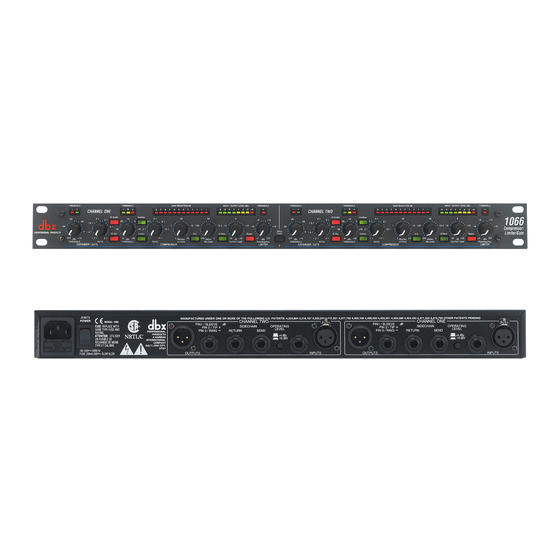
- Page 22 100-120VAC 50/60Hz or 200-240VAC, 50/60Hz, 20W, via a detachable IEC type AC cable. The size of the unit shall be 1.75" x 19" x 7.9" (4.4cmx48.3cmx20.1cm) with a net weight of 5.11 lbs (2.3 kg) and a shipping weight of 7.5 lbs (3.4 kg). The 1U high, full rack width stereo compressor/limiter/gate shall be a dbx 1066.
Need help?
Do you have a question about the DBX 1066 and is the answer not in the manual?
Questions and answers