IFM OY95 S Series Original Operating Instructions

IFM OY95 S Series Original Operating Instructions

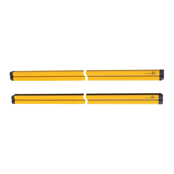
Photoelectric safety sensors (safety light grid) protected area width (range) 8...60 m

Advertisement

Quick Links

Original operating instructions
Photoelectric safety sensors
(safety light grid)
UK
Protected area width (range) 8...60 m
OY95xS

Advertisement

Table of Contents
loading

Summary of Contents for IFM OY95 S Series

  • Page 1 Original operating instructions Photoelectric safety sensors (safety light grid) Protected area width (range) 8...60 m OY95xS...
  • Page 2: Table Of Contents

    Contents 1 Preliminary note ....................4 1.1 Symbols used ....................4 1.2 Warning signs used ..................4 2 Safety instructions ....................5 2.1 Safety-related requirements regarding the application ........6 3 Items supplied......................7 4 Functions and features ..................7 5 Function .......................8 6 Installation......................9 6.1 Installation instructions ..................9 6.2 Calculation of the minimum safety distance ..........10 6.3 Installation of the safety light grids ..............
  • Page 3 9.2.2 Receiver .....................23 10 Operation ......................24 10.1 Switching state of the outputs ..............24 10.1.1 The safe state ...................24 10.1.2 The switched state ................24 10.1.3 Interface classification ..............24 10.2 Functional test of the safety light grids ............25 11 Scale drawing ....................26 11.1 Position of the light beams .................27 12 Technical data ....................28 12.1.1 Safety light grids 2, 3 and 4 beams ..........29...
  • Page 4: Preliminary Note

    1 Preliminary note The instructions are part of the unit. They are intended for authorised persons according to the EMC and Low Voltage Directive and safety regulations. The instructions contain information about the correct handling of the product. Read the instructions before use to familiarise yourself with operating conditions, installation and operation.
  • Page 5: Safety Instructions

    2 Safety instructions • Follow the operating instructions. • In case of non-observance of notes or standards, specially when tampering with and / or modifying the unit, any liability and warranty is excluded. • The unit must be installed, connected and put into operation by a qualified electrician trained in safety technology.
  • Page 6: Safety-Related Requirements Regarding The Application

    ► For applications in the food industry contact your ifm branch office to check the compatibility of the materials of the photoelectric safety sensors with the chemicals used.
  • Page 7: Items Supplied

    • 1 copy operating instructions photoelectric safety sensors, reference no. 704857. If one of the above-mentioned components is missing or damaged, please contact one of the ifm branch offices. 4 Functions and features transmitter (T) receiver (R) P = protected area; I = protected area width (range) H = protected area height The OY95xS safety light grids are multi-beam optoelectronic protective devices to IEC 61496 and consist of one transmitter and one receiver.
  • Page 8: Function

    5 Function The protected area (P) is generated between the transmitter and the receiver and is defined by the protected area height (H) and the protected area width (range) (I). The protected area height is the height protected by the safety light grid. It depends on the design (→...
  • Page 9: Installation

    6 Installation 6.1 Installation instructions The following conditions are to be ensured before installation of the photoelectric safety sensors: • The degree of protection of the electro-sensitive equipment (ESPE) has to correspond with the risk assessment of the machine to be monitored. •...
  • Page 10: Calculation Of The Minimum Safety Distance

    6.2 Calculation of the minimum safety distance There must be a minimum safe distance between the photoelectric safety sensor and the point of danger. This distance must be ensured so that the point of danger cannot be accessed before the hazardous state of the machine has been stopped. ►...
  • Page 11: Installation Of The Safety Light Grids

    Application example: A = hazardous area S = minimum safety distance 6.3 Installation of the safety light grids These versions of OY95xS safety light grids are suitable for access prevention for entire bodies. They must not be used for the protection of hands or body parts! The minimum safety distance (S) is determined using the following formula: S = 1600 (t + t...
  • Page 12: Fixing And Optical Alignment

    6.5 Fixing and optical alignment Correct alignment of the transmitter and the receiver is decisive for the proper function of the photoelectric safety sensors. ► Install the transmitter and the receiver using the supplied mounting accessories so that they are exactly opposite each other. 6.5.1 Optical alignment T = transmitter;...
  • Page 13: Distance Of Reflective Surfaces

    6.6 Distance of reflective surfaces Reflective surfaces close to photoelectric safety sensors can disable the safety function of the system. The minimum distance (D) depends on the protected area width (I) taking into consideration the projection and receiving angles. The minimum distance (D) between reflective surfaces and the protected area (P) must be observed.
  • Page 14: Multiple Systems

    Minimum distance to reflective surfaces 2000 1800 1600 1400 1200 1000 D = minimum distance in [mm]; I = protected area width (range) [m] 6.7 Multiple systems The use of several safety light grids can lead to malfunction and disable the protective function.
  • Page 15: Use Of Corner Mirrors

    6.8 Use of corner mirrors To protect and monitor hazardous areas with access from several sides one or several corner mirrors can be used (available as accessory). By using mirrors the light beam emitted by the transmitter can be sent via several access sides. ►...
  • Page 16: Electrical Connection

    Range 1 Configuration protected area width Functional earth For information about available sockets/connectors see: www.ifm.com → Products → Accessories The protected area width (range) to be used is configured via range 0 and range 1. Configuration protected area width (range)
  • Page 17: Wiring Diagram Receiver

    – Functional earth For information about available sockets/connectors see: www.ifm.com → Products → Accessories Note: Lay the cables of the photoelectric safety sensors separately from sources of interference such as power lines. ► Connect the transmitter and the receiver to the functional earth.
  • Page 18: Operating Modes

    8 Operating modes The different operating modes of the OY95xS series safety light grids can be set via the respective connections on the 8-pole plug of the receiver. Operating modes Connections pin 4 pin 5 pin 6 A Automatic K1_K2 SEL_A SEL_B L + L...
  • Page 19: Automatic Operation

    8.1 Automatic operation If the safety light grids are used in the automatic mode, monitored start is not possible. The safety light grids automatically return to operation with clear protected area, the outputs (OSSDs) are activated. Verify if this is compatible with the risk analysis of your machine. In the automatic mode the OSSD1 and OSSD2 outputs follow the status of the safety light grids: Protected area clear...
  • Page 20: Connection Of External Feedback Contacts

    8.3 Connection of external feedback contacts External feedback contacts can be integrated in the automatic or manual operating mode. The feedback contacts have to be connected in series between the operating voltage and K1_K2 (→ 8 Operating modes / table, fig. B and D). 8.4 Internal test function Type 4 safety light grids continuously perform internal tests.
  • Page 21: Alignment In The Automatic Mode

    9.1.1 Alignment in the automatic mode Receiver orange green yellow Description CLEAR Receiver does not detect any light beam Receiver detects all light beams with a weak signal Receiver detects all light beams ► Align the transmitter so that the green LED of the receiver lights. ►...
  • Page 22: Led States

    9.2 LED states 9.2.1 Transmitter Transmitter Description orange green yellow Activating the system, input test Test condition Normal operating conditions Normal operation at long range (→ 7 Configuration protected area width) Fault...
  • Page 23: Receiver

    9.2.2 Receiver Receiver orange green yellow yellow yellow display CLEAR MAN/ Description AUTO Activating the system, input test Indication of the operating mode (when system is started) Automatic Automatic with monitoring Manual Manually with monitoring Normal operation Protected area interrupted, outputs deactivated Protected area clear, outputs deactivated,...
  • Page 24: Operation

    10 Operation 10.1 Switching state of the outputs The safety light grids have two outputs (OSSDs) on the receiver; the status depends on the condition of the protected area. Any short circuits between the outputs or between an output and the operating voltage (24 V DC or 0 V DC) are detected by the safety light grids as a fault.
  • Page 25: Functional Test Of The Safety Light Grids

    10.2 Functional test of the safety light grids Check the proper function of the safety light grids before work starts. For the functional test an opaque test object has to be used. ► Interrupt the light beams with the test object. First of all in the centre (1) and then close to the transmitter and the receiver (2).
  • Page 26: Scale Drawing

    11 Scale drawing M12x1 M12x1 11,8 13,5 transmitter 1: LED (red) 5: LED (red) 9: LED (yellow) receiver 2: LED (green) 6: LED (green) 10: Display total length* 3: LED (yellow) 7: LED (yellow) 11: LED (orange) 4: LED (orange) 8: LED (yellow) * Available lengths →...
  • Page 27: Position Of The Light Beams

    11.1 Position of the light beams Model Beams Position of the light beams measured from the lower edge of the connector [mm] OY951S 114 - 614 OY952S 114 - 514 - 914 OY953S 114 - 414 - 714 - 1014...
  • Page 28: Technical Data

    12 Technical data Meets the requirements of: Type 4 IEC 61496-1, SIL 3 IEC 61508, SILcl 3 IEC 62061, ISO 13849-1:2015 category 4 PL e Electrical design DC / PNP Operating voltage 24 DC (19.2…28.8) Current consumption Transmitter [mA] 125 Receiver [mA] 250 Outputs (OSSDs)
  • Page 29: Safety Light Grids 2, 3 And 4 Beams

    12.1.1 Safety light grids 2, 3 and 4 beams Number of beams Total length L [mm] 1036 1136 Protected area height [mm] Response time [ms] Safety-related reliability PFH [1/h] Test pulse duration t [µs] Test pulse interval T [ms] Ratio t 13 Troubleshooting The LEDs of the receiver indicate faulty operating states (→...
  • Page 30: System Error

    In case of a system failure an "F" is displayed alternating with an error code. Display Possible cause Troubleshooting Internal fault (main board) Internal fault (main board) Send device to ifm branch office Fault static OSSD outputs for repair. Internal fault (analogue basic input) Configuration change by user Restart system.
  • Page 31: Maintenance, Repair And Disposal

    14 Maintenance, repair and disposal • Maintain the photoelectric protective equipment in accordance with the applicable national regulations in effect within the requested intervals. The tests must be performed by qualified persons. • It is recommended to regularly clean the front panes of the transmitter and the receiver.
  • Page 32: Terms And Abbreviations

    Safety Integrity Level SIL 1-4 to IEC 61508. The higher the SIL the lower the probability that a safety function will fail. Safety Integrity Level claim limit (to IEC 62061) Mission Time Test Interval Technical data and further information at www.ifm.com...
  • Page 33: Annex

    16 Annex 16.1 Check list This check list serves as help for setting up the safety light grids. The requirements in this check list should be met, however depending on the application and the directives / standards referred to. 1. Were the directives / standards valid for safety of machinery complied with? 2.

This manual is also suitable for:

Oy951sOy952sOy953s

Table of Contents