Table of Contents
Advertisement
Quick Links
Advertisement
Table of Contents

Related Manuals for IFM OPD101


Summary of Contents for IFM OPD101
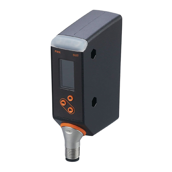
- Page 1 Operating instructions Profile detector OPD101...
-
Page 2: Table Of Contents
OPD101 Contents Preliminary note ............. . - Page 3 OPD101 11.2.2 [Device information]........... 30 11.2.3 [Configuration] .
-
Page 4: Preliminary Note
OPD101 1 Preliminary note You will find instructions, technical data, approvals and further information using the QR code on the unit / packaging or at www.ifm.com. 1.1 Symbols used Requirement Instructions Reaction, result [...] Designation of keys, buttons or indications Cross-reference Important note Non-compliance may result in malfunction or interference. -
Page 5: Safety Instructions
OPD101 2 Safety instructions • The unit described is a subcomponent for integration into a system. – The system architect is responsible for the safety of the system. – The system creator undertakes to perform a risk assessment and to create documentation in accordance with legal and normative requirements to be provided to the operator and user of the system. -
Page 6: Intended Use
OPD101 3 Intended use 3.1 General description The sensor projects a laser line onto the object and determines the height profile of the object along the laser line by means of the triangulation principle. The object to be detected has to be in the sensor's operating range. -
Page 7: Normal Operation
OPD101 In the next step, the sensor continually detects height profiles, compares them to the activated reference profile and generates a matching value. Now the user can set a switching threshold. Interpretation of the matching value (Ò / 7). X axis in [mm]... -
Page 8: Fluctuation Of The Matching Value
OPD101 Matching value provided in [%] Description There is a 50 % match between the measured profile and the activated reference profile. The matching value to be tolerated must be determined by the user during set-up and should be used as switching threshold for the following differentiation:... -
Page 9: Profile Properties
If the value has decreased significantly, e.g. due to changes in the sensor position, it is advisable to teach the object again. The status parameter can be continuously monitored via the ifm parameter setting software “Vision Assistant”. The status parameter can therefore also be used to optimise the sensor position during teaching. -
Page 10: Function
OPD101 4 Function The photoelectric sensor detects the height profile of the object in the operating range, continually or upon triggering, by means of triangulation. Besides, the photoelectric sensor has an IO-Link interface. The sensor can be used in three different modes of operation: •... - Page 11 OPD101 The ifm software package “Vision Assistant” includes a corresponding protocol handler that combines the profile images and visualises them. This simplifies the teaching process (guided teach), as the detection zone of the sensor and the assessment of the profiles is visualised base on the profile images.
-
Page 12: Installation
OPD101 5 Installation 5.1 Installation conditions u Install the unit so that the object to be detected is within the sensor's detection zone. u For direct installation, fix the unit using two M4 screws. Further accessories Ò www.ifm.com Ò Data sheet Ò Accessories. -
Page 13: Front Inclination
OPD101 5.2.2 Front inclination transmitter receiver interrupted laser line Fig. 5: Front inclination If the sensor is inclined forwards or backwards, make sure that the laser line reflected by the object can be detected by the receiver. It can be ensured that the receiver detects the laser line by reducing the inclination angle or rotating the sensor by 180°. -
Page 14: Avoidance Of Multiple Reflections
OPD101 5.2.4 Avoidance of multiple reflections sensor object multiple reflections Fig. 6: multiple reflections u Slightly change the sensor position – e.g. incline the sensor laterally or frontally, increase / decrease the distance to the object. 5.2.5 Avoidance of soiling and ambient light Preferably align photoelectric sensors with the front lens facing downwards or parallel to the earth’s surface. -
Page 15: Electrical Connection
Laser ON / OFF* Trigger input of the PLC *) The function is activated / deactivated via IO-Link or the ifm parameter setting software. In the operating mode “Continuous mode”, OUT1 and OUT2 are configured as complementary switching outputs. Continuous mode (Ò / 27). -
Page 16: Operating And Display Elements
OPD101 7 Operating and display elements 1x yellow LED Switching status OUT1 1X LED green Active LED = power Graphic display Display of the measured matching value Programming button [●] Selection of the parameters and acknowledgement of the parameter values Programming button [▲]... -
Page 17: Set-Up
OPD101 8 Set-up u After installation, electrical connection and programming, check whether the unit operates correctly. w If the unit has been correctly set up, the sensor starts with the “Guided Teach”. “Guided Teach” / teaching of reference profiles (Ò / 18). The settings made last are internally stored by the sensor. -
Page 18: Guided Teach" / Teaching Of Reference Profiles
OPD101 8.1 “Guided Teach” / teaching of reference profiles [Welcome, choose your language] [English] [Deutsch] [Français] [...] [Place object and [Save this object [Region of interest] press con rm] pro le?] [Con rm] [Con rm] [De ne ROI] [Back] [Back] [Back]... -
Page 19: Set Roi
OPD101 w The request [Place object and press confirm] is displayed. w The sensor emits a red laser line with two vertical green ROI markings. u Place the sensor so that the laser line covers the area to be monitored and the object is within the operating range of 150...300 mm. -
Page 20: Set The Position Of The Reference Profile
OPD101 u Move the green marking line using [▲] / [▼]. w The left marking line shifts. u After reaching the requested position, confirm with [●]. w The position of the left marking line is set. The selected section is detected again (new profile). -
Page 21: Switching Threshold
OPD101 8.1.5 Switching threshold matching value switching threshold Fig. 8: Switching threshold u In the next step, the switching threshold for the switching output is set. The standard setting is 90%. w The sensor continually detects new height profiles and compares them to the taught reference profile. -
Page 22: Finishing The Teach Process
OPD101 w [No]: Jump back to the previous step. w [Yes]: The height profile is overwritten and the sensor is put to the RUN mode. 8.1.7 Finishing the teach process u [Select the next step] This step only appears if the selected memory location is free. -
Page 23: Menu
OPD101 9 Menu 9.1 Basic functions Guided Teach [Adj. threshold] [0...100%] [YES] [ROI Markings] [NO] Use Vision Assistant for optimization [Pro le condition] [Pro le X] Pro le X condition [Pro le manager] [Select active pro le] [Add new pro le] [Delete pro le]... -
Page 24: Extended Functions
OPD101 9.2 Extended functions Guided Teach [Factory Reset] [YES] [NO] [Serial number Hardware version [Device Info] Software version FE Software version BE Software version COM Operating hours Start counter] [Con guration] [Display] [Back]... - Page 25 OPD101 [CONT] [Configuration] [Trigger Mode] [TRIG] [HW] [Trigger source] [PDOUT] [no delay] [Output delay mode] [On impulse] [Trigger Delay] [0...5000 ms] [Integration Time] [AUTO...10] [High active] [Output Function] [Low active] [PNP] [Output Logic] [NPN] [local] / [PDOut] [Profile source select] [Back]...
- Page 26 OPD101 [ON] [Display] [Brightness] [OFF] [G1ou], [r1ou] [Colour] [White], [Red], [Green] [Language] [EN, DE, FRA... [Back]...
-
Page 27: Operating Modes
OPD101 10 Operating modes 10.1 Continuous mode The default mode is the “Continuous mode”. The sensor continually measures and compares the measured profiles to the activated reference profile, taking into account the switching threshold. 10.2 Triggered mode In this mode, the sensor starts the measurement after receiving an external trigger signal. - Page 28 OPD101 Switching Example 1 (dashed line): Example 2 (solid line): output OUT2, last object OK, OUT1 = 1 last object faulty, OUT1 = 0 static next object faulty, OUT1 “1 → 0” next object OK, OUT1 “0 → 1” next object OK, OUT1 “0 → 1”...
-
Page 29: Parameter Setting
OPD101 11 Parameter setting During parameter setting the unit remains internally in the operating mode. It continues its monitoring function with the existing parameters until the change has been completed. For the factory settings please refer to the end of these instructions. Factory setting (Ò / 40). -
Page 30: Extended Functions]
[Configuration] (Ò / 31). The menu item [Profile manager] is disabled when [Profile source select] = PDOut. Submenu [Configuration] (Ò / 31). In the latter case, the settings can only be made via IO-Link or the ifm parameter setting software. 11.1.5 [Extended functions] Change to the menu level of extended functions. -
Page 31: Configuration]
OPD101 11.2.3 [Configuration] Configuration of the operating mode and the switching outputs. Submenu [Configuration] (Ò / 31). u Confirm the parameter with [●]. w The display changes to the configuration settings. u Select one of the following options using [▲ / ▼]. 1. [Triggered mode] 2. -
Page 32: Trigger Source]
OPD101 11.3.2 [Trigger source] Set the source for the trigger signal u Confirm the parameter with [●] and select one of the two options [HW] / [PDOUT] using [▲ / ▼]. u Confirm your selection by pressing [●]. w The input signal is confirmed. -
Page 33: Output Logic]
[local]: Active reference profile can be defined via the display menu. Parameter level basic functions (Ò / 29). • [PDOut]: The active reference profile is defined via IO-Link or the ifm parameter setting software “Vision Assistant”. The selection source [local] / [PDOut] is defined exclusively via IO-Link or the ifm parameter setting software “Vision Assistant”. -
Page 34: Language]
11.5.2 Device-specific information You will find the IODDs required for the configuration of the IO-Link unit and detailed information about sensor values, diagnostic information and parameters in the overview table at www.ifm.com. 11.5.3 Parameter setting tools You will find all necessary information about the required IO-Link hardware and software at Ò... - Page 35 OPD101 All functions are described in detail in the IODD.
-
Page 36: Troubleshooting
Activate a reference profile. Parameter level basic functions (Ò / 29). If [Profile source select] = [PDout]: Activate a reference profile via IO-Link or the ifm parameter setting software. This is indicated by [Remote] in the display. 12.2 Error indications in the “Vision Assistant” software Display... -
Page 37: Other Types Of Incorrect Behaviour
OPD101 The profile images detected consist of 352 data points. Faulty data points are indicated as a dashed line in the “Vision Assistant”. These data points are not used for determining the matching value. The data errors and the number of data points concerned for the currently measured height profile are shown in the Vision Assistant. -
Page 38: Maintenance, Repair And Disposal
OPD101 13 Maintenance, repair and disposal Faulty sensors must only be repaired by the manufacturer. u Keep the front lens of the sensor clean. u After use dispose of the unit in an environmentally friendly way in accordance with the applicable national regulations. -
Page 39: Scale Drawing
OPD101 14 Scale drawing programming buttons colour display 28,5 28,5 transmitter receiver laser aperture α = 90° M12 x1 Fig. 11: Scale drawing – dimensions in [mm]... -
Page 40: Factory Setting
OPD101 15 Factory setting Parameter Setting range Factory setting Own setting Switching threshold [%] 0...100 Display of ROI markings in YES / NO the Run mode Operating mode (trigger CONT (continuous CONT mode) measurement) / TRIG (external trigger) Trigger source HW / PDOUT Trigger delay [ms] 0;...
Need help?
Do you have a question about the OPD101 and is the answer not in the manual?
Questions and answers