
Related Manuals for Matsusada Precision AMP Series


Summary of Contents for Matsusada Precision AMP Series
- Page 1 Instruction Manual AMP series MODEL *190.9.036* Rev. 2.2 B/N 190.9.036 F-RA-001-3R2...
- Page 2 F-RA-001-5R0 For Safe Use ◆ Introduction This product generates high voltage and energy. In order to use the product safely and prior to using the product, please read the instruction manual to the end before use in order to use the product safely, because there is a danger of death or serious injury due to electric shock.
- Page 3 F-RA-001-5R0 WARNING ◆ Understand the risk. Products generate high voltage and energy. An electrician or equivalent knowledge must read the instruction manual to the end and familiarize yourself with the proper use and danger of the product. If you want the product to be handled by another person, limit it to those with knowledge of electricity, and have people who are familiar with correct use and danger of the product conduct education and training before handling it, or handle the product under the supervision of those who are familiar with the proper use and danger of the product.
- Page 4 F-RA-001-5R0 WARNING ◆ Designed for indoor use Use the product indoors. Do not use it outdoors or indoors where there is a possibility of water leakage, flooding, or crown. ◆ About operating temperature and humidity Use within the range of operating temperature and humidity stated in the instruction manual. Do not use it in a place where the ambient temperature becomes higher than the operation temperature of the product or in a narrow closed place.
- Page 5 F-RA-001-5R0 CAUTION ◆ Install horizontally. Do not install the product in the reverse direction and the lateral direction. Internal heat dissipation becomes insufficient, parts deteriorate, there is a risk of smoke and fire. ◆ Do not install in the place where cool air blows directly. There is a danger of condensation, leakage current and burnout.
-
Page 6: Table Of Contents
Table of Contents Table of Contents Page 1 Introduction 1-1 Introduction 1-2 Unpacking the amplifier 1-3 Environmental requirements 1-4 Points to be careful about in handling and care 1-5 Additional points to be noted for operation of HV amplifier 1-6 Troubleshooting 2 Product List 3 Exterior view diagram 9-20... -
Page 7: Introduction
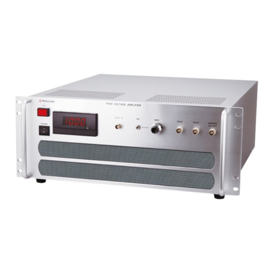
1 Introduction 1 Introduction 1-1 Introduction Thank you very much for your purchase of our product, HIGH VOLTAGE AMPRIFIER. We have done our best for the quality control of our products. Please handle this unit properly according to this instruction manual so that you can use the full performance of this unit safely for long. -
Page 8: Points To Be Careful About In Handling And Care
1 Introduction 1-4 Points to be careful about in handling and care. How to GROUND ・ This product uses Input AC cable with earth connection. For the safety operation earth connection must be connected to safety earth ground. WHEN TOUCHING LOAD AFTER TURNING OFF HIGH VOLTAGE Make the setting of an output voltage to zero (0). -
Page 9: Additional Points To Be Noted For Operation Of Hv Amplifier
① Rated maximum voltage or current cannot be obtained. ② The waveform at constant current operation or current monitor is distorted or changed View of high - voltage amplifier’s charge and discharge current Vout t AMP series Vcon High-voltage Output line Current monitor Wave form amplifier Load io... - Page 10 1 Introduction Capacitive Load When operated with a capacitive load of more than 100pF (including floating capacity of output cable), the output might oscillate. In such a case put a high voltage resister of 100Ω (0.1μF) to 1kΩ (1000pF) in series to output. Please also note that with capacitive load the bandwidth is limited according to the formula below.
- Page 11 1 Introduction Slew Rate The responsibility of our high speed amplifier is determined with slew rate (SR). The step responsibility of our amplifier is as shown in fig.3. SR = △V/μS In case of output amplitude is smaller the response time become shorter. Vocn-in HVout 700V...
-
Page 12: Troubleshooting
1 Introduction 1-6 Troubleshooting ・ In case no output voltage: 1. Check input voltage is correct ・ 100V~240V AC±10% 50/60Hz(It depend on things)single phase of input voltage. ・ Control voltage –10V to 10V at the time of controlling over external voltage. 2. -
Page 13: Product List
2 Product List 2 Product List of each model are following. Specifications Frequency Response Dimensions Peak (-3dB) Slew (mm) Output Weight Output current outpour Small model H×W×D current Rate (kg) voltage power ( /1mSec bandwidth Full scale (Except (DC+AC max) [V/μs] max)... - Page 14 2 Product List <Specifications> Input voltage 230VAC±10% 50/60Hz single phase 10A typ.(AMP-0.6B2000, AMP-1B1200) 230VAC±10% 50/60Hz single phase 5A typ.(AMP-2B200, AMP-5B80, AMP-10B40, AMP-20B20, AMP-30B10 ) 200~240VAC±10% 50/60Hz single phase 10A typ.(AMP-40B20) 100~240VAC±10% 50/60Hz single phase 3.5A typ@100VAC.(AMP-10B10) Control voltage -10V to +10V (input impedance greater than 10kΩ) DC bias front panel 10 tern potentiometer enables setting between -100% to +100%...
-
Page 15: Exterior View Diagram
3 Exterior view diagram 3 Exterior view diagram 3-1 Front view AMP-10B10 ③ ② HIGH VOLTAGE AMPLIFIER REMOTE BIAS ON/OFF Vcon-in POWER ① ④ ⑤ ⑥ ⑦ ⑧ ⑨ ① POWER ON/OFF switch ⑥ Bias voltage setting dial ② HV ON/OFF switch (10-turn potentiometer) ③... - Page 16 3 Exterior view diagram AMP-2B200、5B80、10B40、20B20 ② ③ ⑥ ⑦ ⑧ ④ ⑨ ⑤ ① ④ REMOTE ON/OFF ① POWER ON/OFF switch ⑥ Bias voltage setting dial ② HV ON/OFF switch (10-turn potentiometer) ③ Output voltmeter 3 digital meter ⑦ Output current monitor terminal ½...
- Page 17 3 Exterior view diagram AMP-0.6B2000 ④ ⑤ ② ③ ⑥ ⑦ ⑧ ⑨ ① ④ REMOTE ON/OFF ① POWER ON/OFF switch ② HV ON/OFF switch ③ Output voltmeter 3 digital meter ½ ④ External voltage input terminal ⑤ Bias voltage ON/OFF switch ⑥...
- Page 18 3 Exterior view diagram AMP-1B1200 ⑧ ⑦ ④ ⑤ ⑨ ③ ⑥ ② ① ① POWER ON/OFF switch ② HV ON/OFF switch ③ Output voltmeter 3 digital meter ½ ④ External voltage input terminal (Vcon-in terminal) ⑤ Bias voltage ON/OFF switch ⑥...
- Page 19 3 Exterior view diagram AMP-30B10 ① ② ③ ④ ⑤ ⑥ ⑦ ⑧ ⑨ ④ ④ ④ ⑩ ① POWER ON/OFF switch ⑥ Bias voltage setting dial ② HV ON/OFF switch (10-turn potentiometer) ③ Output voltmeter 3½ digital meter ⑦ Output current monitor terminal ④...
- Page 20 3 Exterior view diagram 【 】 LOc、LCc、LCx options ① ② ③ ④ ⑤ ⑥ ⑧ ⑨ ⑩ ⑪ ⑫ ⑦ ④ ④ ④ ④ Cutoff Limit ⑬ ① POWER ON/OFF switch ⑦ Cutoff/Limit changeover switch ② HV ON/OFF switch (Only when LCx option is installed) ③...
- Page 21 3 Exterior view diagram AMP-40B20 ④ ⑦ ② ③ ⑥ ⑧ ⑨ ⑤ ① REMOTE ON/OFF ① POWER ON/OFF switch ⑥ Bias voltage setting dial ② HV ON/OFF switch (10-turn potentiometer) ③ Output voltmeter 3½ digital meter ⑦ Output current monitor terminal ④...
- Page 22 3 Exterior view diagram Rear view AMP-10B10 ① ② ③ FUSE ④ ① Output connector ② GROUND terminal ③ FUSE ④ AC input connector AMP-2B200、5B80、10B40、20B20 ① AC230V ② ③ ④ ① Output connector ② GROUND terminal ③ FUSE ④ AC Input connector...
- Page 23 3 Exterior view diagram AMP-0.6B2000 INPUT OUTPUT ① ② ③ ① Output terminal ② Ground terminal ③ AC input terminal...
- Page 24 3 Exterior view diagram AMP-1B1200 ① ③ ② ① Output connector ② Ground terminal ③ AC input terminal...
- Page 25 3 Exterior view diagram AMP-30B10 AC230V ① ② ③ ① GROUND terminal ② FUSE ③ AC Input connector...
- Page 26 3 Exterior view diagram AMP-40B20 ① ② ③ ④ ① Output connector ② FUSE ③ AC input connector ④ GROUND terminal...
-
Page 27: Instructions For Operation
4 Instruction for operation 4 Instructions for operation 4-1 Overview This product is a high speed and high voltage bipolar amplifier developed using the knowledge and expertise gained through long years of experience with high voltage. This is highly reliable and high performance product with all solid state parts. This product is designed on the assumption that it is integrated into equipment and used. - Page 28 4 Instructions for operation 2. Connect the Input AC cable. For the safety, earth connection must be connected to a properly grounded outlet. Connection method for single-phase input If the AC input connector on the rear panel is an AC inlet, insert the power cable connector. AC input connector (Form:AC inlet) Connect AC code as follows...
- Page 29 4 Instructions for operation 4. Turn on the HV ON/OFF switch. The red indicator will light up to indicate that the amplifier is ready for operation. If steps 3. and 4. are performed in the reverse order, the unit will be left in stand – by mode.
-
Page 30: Using The Bias
4 Instructions for operation 4 - 3 Using the bias Turning the bias voltage ON/OFF switch to the ON position makes it possible to vary bias voltage using the BIAS knob. Read the setting voltage from the scale on the dial. Dial Scale Output Voltage 000 (CCW) -
Page 31: Output Current Monitor
4 Instructions for operation 4-5 Output current monitor 10V(Positive output current→+10V, Negative output current→-10V) is output from the front panel output current monitor terminal when operated with rated output peak current. The output impedance is 1kΩ Up to 3kHz Bandwidth . AMP-0.6B2000, 1B1200,2B200, 【Front Panel】... -
Page 32: Other Functions
4 Instructions for operation *1 Cautions for use of open collector. When an open collector is used with , use them according to the Remote ON/OFF function following rule. DEFINITION OF OPEN COLLECTOR OUTPUT SWITCH OPEN COLLECTOR Short 0.4V or less (10mA) Open 2V or more... -
Page 33: Output Peak Current
4 Instructions for operation 4-8 Output peak current Output peak current of around 2 or 3 times more than rating can be obtained. It suppresses the distortion of waveform with capacitive load. Peak allowable time is 1ms. 120mApk (Example) AMP-10B40 <... -
Page 34: Optional Features
5 Optional features Optional features 5-1 List of optional features This product is equipped with all features which have been checked in the table below, and you should therefore be sure to read the sections of the user’s manual dealing with these features. -
Page 35: Technical Note (Current Of Capacitive Load)
Technical note 〔 Output current of capacitive load 〕 In case the capacitance value inclusive of that in the high voltage cable is higher than allowed, amplifier may encounter malfunction even though the setting parameter is within the power supply’s rated value due to output overcurrent.
Need help?
Do you have a question about the AMP Series and is the answer not in the manual?
Questions and answers