Table of Contents
Advertisement
Quick Links
Advertisement
Table of Contents

Related Manuals for Matsusada Precision ASX-3R5


Summary of Contents for Matsusada Precision ASX-3R5
- Page 1 Instruction Manual ASX-3R5 MODEL *068.9.005* B/N 068.9.005 Rev. 2.8 F-RA-001-3R0...
-
Page 2: For Safe Use
F-RA-001-5R0 For Safe Use ◆ Introduction This product generates high voltage and energy. In order to use the product safely and prior to using the product, please read the instruction manual to the end before use in order to use the product safely, because there is a danger of death or serious injury due to electric shock. - Page 3 F-RA-001-5R0 WARNING ◆ Understand the risk. Products generate high voltage and energy. An electrician or equivalent knowledge must read the instruction manual to the end and familiarize yourself with the proper use and danger of the product. If you want the product to be handled by another person, limit it to those with knowledge of electricity, and have people who are familiar with correct use and danger of the product conduct education and training before handling it, or handle the product under the supervision of those who are familiar with the proper use and danger of the product.
- Page 4 F-RA-001-5R0 WARNING ◆ Designed for indoor use Use the product indoors. Do not use it outdoors or indoors where there is a possibility of water leakage, flooding, or crown. ◆ About operating temperature and humidity Use within the range of operating temperature and humidity stated in the instruction manual. Do not use it in a place where the ambient temperature becomes higher than the operation temperature of the product or in a narrow closed place.
- Page 5 F-RA-001-5R0 CAUTION ◆ Install horizontally. Do not install the product in the reverse direction and the lateral direction. Internal heat dissipation becomes insufficient, parts deteriorate, there is a risk of smoke and fire. ◆ Do not install in the place where cool air blows directly. There is a danger of condensation, leakage current and burnout.
-
Page 7: Table Of Contents
CONTENTS CONTENTS For Safe Use ⅰ CONTENTS ⅶ 1 Introduction 1-1 Introduction 1-2 Unpacking the POWER SUPPLY 1-3 Installation conditions 1-4 CAUTION FOR HANDLING 1-5 How to switch Input Voltage 1-6 For safer operation 1-7 Trouble Shooting 2 Exterior view diagram 2-1... -
Page 10: 1 Introduction
1. Introduction 1 Introduction 1. Introduction 1-1 Introduction Thank you very much for your purchase of our product HIGH VOLTAGE POWER SUPPLY. We have done our best for the quality control of out products. Please handle this unit properly according to this instruction manual so that you can use the full performance of this unit safely for long. -
Page 11: 1-4 Caution For Handling
1.Introduction 1-4 CAUTION FOR HANDLING ! WHEN TOUCHING LOAD AFTER TURNIG OFF A HIGH VOLTAGE. WARNING 1. Set an output voltage to zero (0). Or turn off the HV ON/OFF switch. 2. Turn off the POWER ON/OFF switch 3. Earthing an output for longer than 10 seconds, check and confirm that voltage is zero at another voltmeter (for high voltage). -
Page 12: 1-5 How To Switch Input Voltage
1. Introduction 1-5 How to switch Input Voltage ・ Place a screw driver or coin on the dent of the input voltage select switch - and set it to the desired input. 115V ・ For example the illustration indicates 100V±10% 50/60Hz input. !... -
Page 13: 2 Exterior View Diagram
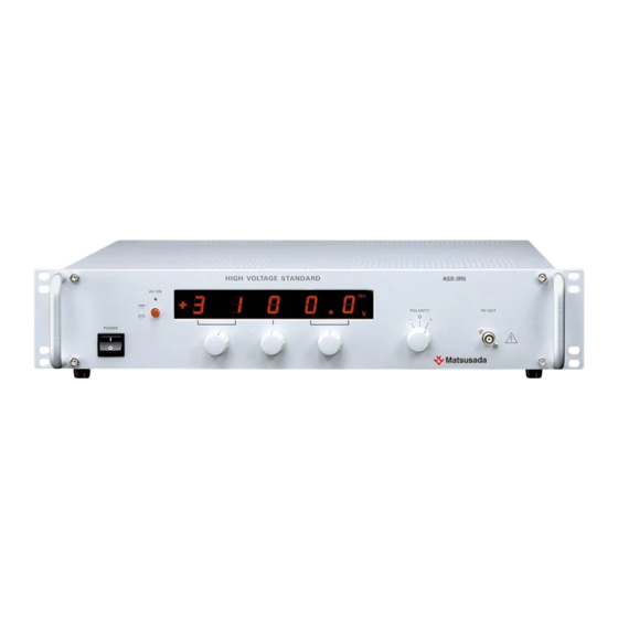
2 Exterior view diagram 2 Exterior view diagram 2-1 Front panel ③ ④ ASX-3R5 HV-ON ② POLARITY HV-OUT - + POWER ① ⑤ ⑤ ⑥ ⑦ ⑤ ①POWER ON/OFF Switch ②HV ON/OFF Switch : Push to ON. Push again to OFF ③HV LED :... -
Page 14: 2-2 Rear Panel
2 Exte erior view diagr r am 2-2 Rea ar panel ② ⑥ ④ ⑨ HV-OUT 115V FUSE BATTERY LINE E VOLTAGE RA ANGE AC LINE INPUT ⑧ ① ② ③ ④ ⑤ ⑥ ⑥ ⑦ ⑧ ⑨ ⑩ ⑪ ⑪... -
Page 15: 3 Basic Operation
3 Basic Operation 3 Basic Operation 3-1 Summary This supply is designed for such applications as Photo multiplier, Nuclear Instruments or Radiation detectors which require high accuracy, high stability and ultra low ripple. With digital setting, accurate and quick output voltage setting is possible. 3-2... -
Page 16: 3-3 Check Points
3 Basic Operation 3-3 Check Points Operation Display panel indication Output HV LED Reset Turn the POWER * 0000.0V 1. Turn the HV ON/OFF switch off. ON/OFF switch off * No ± indication (short with 2. Polarity indication light on. 1.5MΩ) Polarity select switch become while HV ON/OFF... -
Page 17: 3-4 Other Function
3 Basic Operation 3-4 Other Function Over Current Protection This supply has Over Current Protection function, and cut off the output at 105% of maximum output current.(HV LED light off). To reset, please refer to 3-3 c [How to recover from Cut-off status] Memory of adjusted value This supply has a function to memorize the adjusted value. -
Page 18: 4 Specification Of Options
4. SPECIFICATION OF OPTIONS 4 SPECIFICATION OF OPTIONS 4-1 List of optional features This product is equipped with all features which have been checked in the table below. Ask for options when order. symbol name contents □ Remote HV ON/OFF switch(LS) HV output ON/OFF by remote control Remote Interlock(Manual Reset) (LD) Output can be turned OFF with door switch... -
Page 19: 4-4 Remote Switch On/Off (Ls)
4. SPECIFICATION OF OPTIONS 4-4 Remote switch ON/OFF(LS) The output can be turned on and off with remote switch. 〈CONNECTION DIAGRAM〉 Terminal for Remote Switch Terminal board for rear S.G. ① ② ③ panel options. Remote Switch Remote switch action by switch. S H O R T ……... -
Page 20: 4-6 Voltage Monitor (L2)
4. SPECIFICATION OF OPTIONS 4-6 Voltage Monitor (L2) When maximum output voltage, the supply outputs +/-10V(the same polarity of output) from the output voltage monitor terminal on the rear panel. Output impedance is 1KΩ Output Voltage Output Voltage Control +3100.0V +10V -3100.0V -10V... -
Page 21: 4-9 Gp-Ib Control (Lg)
4. SPECIFICATION OF OPTIONS 4-9 GP-IB Control (LG) <Function> Following function is available with GP-IB control. ・ Output voltage setting. ・ Output ON/OFF ・ Output polarity setting ・ Local setting Address Delimiter <Settings address and delimiter for GP-IB> On the rear panel there is an eight DIL switch labeled "ADDRESS". -
Page 22: 4-10 Rs-232C Control (Lrs)
4. SPECIFICATION OF OPTIONS 4-10 RS-232C Control (LRs) 〈Function〉 Following function is available with RS-232C control. ・ Output voltage setting. ・ Output ON/OFF ・ Output polarity setting. ・ Local setting. 〈Communication method〉 Communication speed : Asynchronous 9600 〔bps〕(Fixed) Data length :... -
Page 23: 4-11 Operation Of Gp-Ib/Rs-232C Control
4. SPECIFICATION OF OPTIONS 4-11 Operation of GP-IB/RS-232C Control 1. Turn the POWER ON/OFF switch on. Display panel light up after blinking several seconds. 2. Turn the HV ON/OFF switch on. For your safety set the polarity select switch 0, otherwise voltage outputs. - Page 24 4. SPECIFICATION OF OPTIONS REN command This command enables remote control of the power supply. (Syntax) (Description) ・ When ASX receives REN command, “REN” LED lights up. ・ Value of output voltage become 0000.0V ・ Output turn off ・ Wait more than 2 seconds to send SW1 command after REN command is sent. ・...
- Page 25 4. SPECIFICATION OF OPTIONS (Sample program for test operation) GP-IB option case RS-232C option case 10 ISET IFC 10 OPEN “COM1 : N81N” AS# 1 20 ISET REN 20 INPOUT “COMMAND ->”, D$ 30 INPUT “COMMAND->”, D $ 30 PRINT #1, D$ 40 PRINT @1 ;...
Need help?
Do you have a question about the ASX-3R5 and is the answer not in the manual?
Questions and answers