
Related Manuals for Matsusada Precision AK Series


Summary of Contents for Matsusada Precision AK Series
- Page 1 Instruction Manual AK series MODEL (3kW, 4kW) *030.9.010* B/N 030.9.010 Rev. 1.0 F-RA-001-3R2...
- Page 2 ◆ No patent liability is assumed with respect to the use of the information contained herein. Moreover, because Matsusada Precision is constantly striving to improve its high-quality products, the information contained in this manual is subject to change without notice.
-
Page 3: For Safe Use Of The Product
Bistable push button switch for preventing electric shock) Indicates the possible danger of death if Bistable push button switch you drink it and burns or blindness if it attaches. Indicates the possible danger of exposure Alternative Current to radiation. AK series Matsusada Precision... - Page 4 It may result in electric shock or fire. Regarding the input voltage Check the page describing the input terminals and input voltage in the instruction manual. Do not provide any voltage out of the specifications. AK series Matsusada Precision...
- Page 5 In order to avoid electric shock, ground the terminals to discharge using a short-circuit grounding apparatus and check the voltage again. The terminals here mean all terminals like input and output terminals and terminals for communications and remote controls. AK series Matsusada Precision...
- Page 6 It requires to be replaced at regular intervals to extend the lifetime. For the replacement, contact us. (It requires a replacement charge separately. Do not replace it by yourself, as there is a risk of electric shock.) AK series Matsusada Precision...
-
Page 7: Table Of Contents
3-2-3 External Voltage Limit Protection Advanced Operation 4-1 Introduction 4-2 Function of TB1 Interface Connector 4-3 Selecting Internal Control (INT)/External Control (EXT) 4-4 External Voltage Control 4-4-1 Voltage Control by External Voltage (LV) 4-4-2 Current Control by External Voltage (LC) AK series Matsusada Precision... -
Page 8: Table Of Contents
4-8-1 Output Current Monitor (L1) 4-8-2 Output Voltage Monitor (L2) 4-9 HV Status Signal Options 5-1 Floating Ground (LF) 5-2 Slow Start (LW) 5-3 Overload Trip (LOc) 5-4 AC Input 400V L (400V) 5-5 Master Slave (LMs) AK series Matsusada Precision... -
Page 9: Introduction
Remote switch ON/OFF, Door switch, Output status signal output (internal relay) Temperature Temperature 0 to 40°C (Operating)、-20 to 70°C (Storage) Humidity 30 to 80% RH (no condensation) These Specifications are at the maximum rated output after a warm-up period unless otherwise specified. AK series Matsusada Precision... -
Page 10: Unpacking The Power Supply
25kg, and It is dangerous for one person to carry. Two persons or more should hold to carry or a cart should be used to carry. ● Do not place the power supply where the possibility of condensation. AK series Matsusada Precision... -
Page 11: Connecting Ac Line Input Cord
● Any wrong voltage input may damage the unit. L1 L2 L3 Fig. 1.1 1 to 60kV: 80 to 120kV: AC line input connector AC line input connector AK series Matsusada Precision... -
Page 12: How To Ground
If the Load frame is grounded (over 3kV output models) ・ Output cable Ground terminal Load Rack – mount case Wires should be : Load frame ・more than 5SQ MUST ・less than about 2m ・not bared Ground Ground at one point MUST Fig. 1.3 AK series Matsusada Precision... - Page 13 ● Make sure to connect the GROUND terminal correctly as shown in Fig. 1.2, Fig. 1.3, Fig. 1.4 and Fig. 1.5. Poor grounding is dangerous and may cause an electric shock or damage the power supply. ● When load short-circuit or discharge is forecasted, make the GROUND cable thicker and shorter. AK series Matsusada Precision...
-
Page 14: Connecting To Load
Check if the high voltage connector plug (arrow in the figure below) is contaminated. The dirty plug may cause electric discharge in the connector. Wipe away the dirt with cloth soaked in alcohol and dry completely to use. AK series Matsusada Precision... -
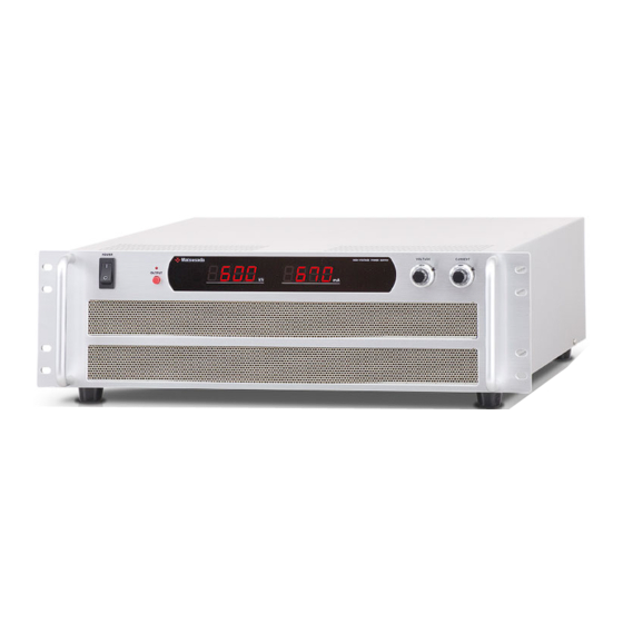
Page 15: Exterior View Diagram
Remote. Unit is in remote control mode. CV ④ Constant Voltage (CV) mode. Unit is CV mode. CC ⑤ Constant Current (CC) mode. Unit is CC mode ⑥ Output current digital meter ⑦ Output voltage digital meter AK series Matsusada Precision... -
Page 16: Rear Panel
⑦ Fig. 2-4 Rear panel (80 to 120kV) ⑥ ① Output connector ② LF terminal (for LF option) ③ I nterface connector (TB1) ④ AC input connector ⑤ P.E( ) ⑥ Exhaust holes ⑦ Ground terminal AK series Matsusada Precision... -
Page 17: Dimensions (1 To 60Kv)
2 Exterior View Diagram 2-4 Dimensions (1 to 60kV) AK series Matsusada Precision... -
Page 18: Dimensions (80 To 120Kv)
2 Exterior View Diagram 2-5 Dimensions (80 to 120kV) AK series Matsusada Precision... -
Page 19: Normal Operation
Warning: Never touch the load immediately after the operation ends. It is very dangerous. When capacitive load is used, carefully connect the load to the ground and make MUST sure that electricity is discharged. AK series Matsusada Precision... -
Page 20: Overvoltage Protection (O.v.p.)
This unit is equipped with the external voltage limit protection. To protect the power supply and the load, the voltage and current is limited at approx. 110% of the maximum rated voltage or current even if any abnormality occurs. AK series Matsusada Precision... -
Page 21: Advanced Operation
Internal control/external control select control Remote switch ON/OFF Short = HV ON Open = HV OFF Spare (out of use) Spare (out of use) Spare (out of use) 20-17 short Current Control: EXT/INT select Internal current control 25-2 short AK series Matsusada Precision... -
Page 22: Selecting Internal Control (Int)/External Control (Ext)
Fig. 4-2 Selecting internal control/external control Precautions in using the open collector*1 Use the open collector according to the following. List 4-2 Open collector Output Switch Open collector Short Under 0.4V (10mA) Open Over 2V (Open 5V) AK series Matsusada Precision... -
Page 23: External Voltage Control
The external volume 5kΩ can control the output voltage within the range of 0 to 100%. 4-5-2 External Volume Current Control (LRc). The external volume 5kΩ can control the output current within the range of 0 to 100%. AK series Matsusada Precision... -
Page 24: Remote Switch On/Off(Ls)
When the output is ON, the front panel OUTPUT LED is lit. This function is effective regardless of selection of INT/EXT. Switch 2 Open = Output OFF Switch 2 Short Switch 2 = Output ON “L” = HV ON Remote switch Fig. 4-5 AK series Matsusada Precision... -
Page 25: Door Switch (Ld) = Interlock
Keep pressing the switch is not used. upper square part with a slotted screwdriver and pull it out. Switch 3 Open = output OFF Switch 3 Switch 3 Short = output ON Door switch Fig. 4-6 AK series Matsusada Precision... -
Page 26: Output Current Monitor, Output Voltage Monitor
When the OUTPUT ON/OFF switch is ON, the internally built-in relay contact is ON. 10Ω,1/2W HV status signal Fig. 4-8 Caution When the contact is open, the voltage is 30Vdc MAX and the permissible current is 100mA MAX. AK series Matsusada Precision... -
Page 27: Options
When this function is not used, attach the short-circuit fitting between the CASE terminal and the 0V terminal to connect. (See Fig. 5-2.) When this function is used, the device connected to TB1 should be floating. Caution AK series Matsusada Precision... -
Page 28: Slow Start (Lw)
The external switch can reset the cut-off condition at output over current. (The open collector can also do.) Switch 4 Short=HV reset Open Short Reset Switch 4 “L” = HV reset Fig. 5-3 Remote reset AC Input 400V L(400V) Input voltage: AC400V±10%, 50/60Hz, Three phase AK series Matsusada Precision... -
Page 29: Master Slave (Lms)
When monitoring the output or status, connect measurement equipment to master unit. Switch the of external Change 2 connections of connectors at master unit side shown below. Open MASTER Short Refer to chapter 4 [Advanced Operation], for the other advanced operation AK series Matsusada Precision... - Page 30 Revision History Rev. No. Rev. Date Revised contents 2015/06 First edition 2020/08 Changed the format. AK series Matsusada Precision...
- Page 31 AK series Matsusada Precision...
Need help?
Do you have a question about the AK Series and is the answer not in the manual?
Questions and answers