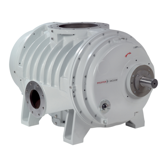
Pfeiffer Vacuum OKTA 8000 G Operating Instructions Manual
Roots pump
Hide thumbs
Also See for OKTA 8000 G:
- Operating instructions manual (64 pages) ,
- Operating instructions manual (58 pages)
Table of Contents
Advertisement
Quick Links
Advertisement
Table of Contents

Related Manuals for Pfeiffer Vacuum OKTA 8000 G


Summary of Contents for Pfeiffer Vacuum OKTA 8000 G
- Page 1 OPERATING INSTRUCTIONS Original OKTA 8000 G Roots Pump...
- Page 2 Dear Customer, Thank you for choosing a Pfeiffer Vacuum product. Your new roots pump should support you in your individual application with full performance and without malfunctions. The name Pfeiffer Vacuum stands for high-quality vacuum technology, a comprehensive and complete range of top-quality products and first-class service.
-
Page 3: Table Of Contents
Table of contents Table of contents About this manual Validity 1.1.1 Applicable documents 1.1.2 Product variants affected Target group Conventions 1.3.1 Instructions in the text 1.3.2 Pictographs 1.3.3 Stickers on the product 1.3.4 Abbreviations Safety General safety instructions Safety instructions Safety precautions Product usage limits Proper use... - Page 4 Shutting down for longer periods Recommissioning Disposing of the vacuum pump Malfunctions Service solutions from Pfeiffer Vacuum Spare parts 11.1 Set of seals for version with RSSR 11.2 Set of seals for version with axial face seal (axial face seal separate) 11.3 Axial face seal, complete...
- Page 5 Requirements on the cooling water composition............27 Tbl. 6: Max. permissible flushing quantity................36 Tbl. 7: Maintenance intervals....................39 Tbl. 8: Troubleshooting......................48 Tbl. 9: Conversion table: Pressure units................52 Tbl. 10: Conversion table: Units for gas throughput.............. 52 Tbl. 11: Technical data for Okta 8000 G................53 5/56...
- Page 6 Fig. 14: Sealing gas connection.................... 32 Fig. 15: Temperature monitoring................... 33 Fig. 16: Changing the lubricant....................40 Fig. 17: Replacing the sealing oil for radial shaft seal rings..........42 Fig. 18: Elastic bolt coupling (example).................44 Fig. 19: Okta 8000 G......................54 6/56...
-
Page 7: About This Manual
Keep the manual for future consultation. 1.1 Validity These operating instructions are for customers of Pfeiffer Vacuum. They describe the function of the designated product and provide the most important information for safe usage of the product. The de- scriptions comply with applicable directives. All information provided in these operating instructions refer to the current development status of the product. -
Page 8: Conventions
This section describes all the stickers on the product along with their meaning. Rating plate (example) The rating plate is located on the front side above the sight D-35641 Asslar glass Mod.: Okta 8000 G Mod.-No.: PP G80 xxx Ser. -No.: 12xxxxxxxxx max. 2200 1/min Oil: 21,0 l S(N): max. -
Page 9: Abbreviations
About this manual Fig. 1: Position of the labels on the product Hot surface warning sign Fill lubricant note Rating plate Direction of rotation arrow (cast in pump housing) D1 lubricant note 1.3.4 Abbreviations Abbreviation Explanation Okta "G" Gas circulation cooled roots pump width across flats Clearance between both coupling halves RSSR... -
Page 10: Safety
Safety 2 Safety 2.1 General safety instructions This document includes the following four risk levels and one information level. DANGER Imminent danger Indicates a hazardous situation which, if not avoided, will result in death or serious injury. ► Instructions on avoiding the hazardous situation WARNING Possibly imminent danger Indicates a hazardous situation which, if not avoided, could result in death or serious injury. - Page 11 Safety Risks during installation DANGER Danger to life from electric shock Contact with exposed and live elements generate an electric shock. Incorrect connection of the mains supply leads to the risk of live housing parts that can be touched. There is a risk to life. ►...
- Page 12 Safety Risks during operation WARNING Danger of poisoning due to emission of toxic process gases from the exhaust During operation with no exhaust line, the vacuum pump allows exhaust gases and vapors to escape freely into the air. In processes involving toxic media, there is a risk of injury and danger to life due to poisoning.
-
Page 13: Safety Precautions
Safety WARNING Risk of crushing from rotating parts Fingers and hands may be caught by rotating pistons within the connection flange. This results in se- vere injuries. ► Keep limbs out of the reach of the roots pump. WARNING Health hazard and environmental damage from toxic contaminated lubricant Toxic process media can cause lubricant contamination. -
Page 14: Product Usage Limits
► Operate the vacuum pump within application limits (see: Product usage limits and Technical data). ► Adhere to the installation, commissioning, operating, and maintenance instructions. ► Use only accessory parts recommended by Pfeiffer Vacuum. 2.6 Foreseeable improper use Improper use of the product invalidates all warranty and liability claims. Improper use is any, even unin- tended, use, which is contrary to the product purpose;... - Page 15 ● Use of the vacuum pump in areas with strong electrical, magnetic or electromagnetic fields ● Use of the vacuum pump with open vacuum and/or fore-vacuum flange open to the atmosphere ● Using lubricants not specified by Pfeiffer Vacuum ● Using pipes to lift the vacuum pump ●...
-
Page 16: Product Description
The direction of flow of the vacuum pumps is vertical from top to bottom, so that any accumulating fluids cannot become deposited in the pump housing. Fig. 2: Design, Okta 8000 G Lubricant filling plug Sealing gas connection (2×) Vacuum flange... -
Page 17: Product Identification
10000 hPa. 3.2 Product identification To ensure for a clear identification of the product when communicating with Pfeiffer Vacuum, always keep all of the information on the rating plate to hand. The following information is shown on the rating plate: ●... -
Page 18: Product Features
Product description 3.3 Product features Flange types Vacuum connection/ Cooling gas con- Measurement Barrier gas nection connections connections Fore-vacuum con- nection ANSI (150 lbs) 12" 6" 1 × G 3/8" 4 × G 3/8" 1 × G 1/2" DN 300 PN 10 DN 150 PN 10 DIN ISO NW 320 ISO-F... -
Page 19: Transportation And Storage
● Fill the gear and bearing chambers with lubricant only once the final installation position is reached. Pfeiffer Vacuum recommends keeping the transport packaging and original protec- tive cover. General information regarding safe transport 1. Observe weight specified on the rating plate. -
Page 20: Storing The Vacuum Pump
– In rooms with humid or aggressive atmospheres, seal the roots pump airtight in a plastic bag, together with a drying agent. – After a storage period of 2 years, Pfeiffer Vacuum recommends changing the lubricant. The best corrosion protection for the roots pump is achieved by evacuating and then filling the suction chamber with nitrogen. -
Page 21: Installation
Pfeiffer Vacuum are excluded. ► Use approved lubricant only. ► Use other application-specific lubricant only after consultation with Pfeiffer Vacuum. The lubricant type specified for the gear and bearing chamber as well as the respective filling quantity are indicated on the rating plate. -
Page 22: Filling With Sealing Oil
Installation max. min. Fig. 5: Filling with lubricant Sight glass, bearing chamber Sight glass, gear side Lubricant filling plug Lubricant drain plug Lubricant filling plug Lubricant drain plug Procedure 1. Unscrew both lubricant filler screws. 2. Fill the lubricant on both sides according to the sight glass. –... -
Page 23: Fill The Sealing Medium For The Axial Face Seal
Installation Fig. 6: Filling sealing oil for radial shaft seal rings Oiler Consumable ● Sealing oil (lubricant) Procedure 1. Open the filler flap on the oiler. 2. Fill the oiler with lubricant to max. halfway. 3. Close the filler flap. 5.4 Fill the sealing medium for the axial face seal NOTICE Damage to the axial face seal due to aging of the sealing medium... -
Page 24: Connecting The Vacuum Side
Installation Fig. 7: Sealing agent container for axial face seal Sealing agent filler neck Sealing ring housing Sealing agent container Sealing agent outlet Sight glass Cooling water connection Sealing agent drain Compressed air connection Sealing agent inlet Consumable ● Sealing medium container including fittings ●... -
Page 25: Connecting The Fore-Vacuum Side
(optional). The dimensioning of the gas cooler and the cold gas circulation pipe is the responsibility of the operat- ing company. As an alternative, Pfeiffer Vacuum can assist you with the authorization of the dimension- ing. -
Page 26: Connecting The Cooling Water Supply
Installation Fig. 8: Roots pump with tubular gas cooler Vacuum flange Cooling water connection, inlet Cooling gas connection Fore-vacuum connection Fore-vacuum flange Gas cooler Measurement connection Cold gas circulation pipe Cooling water connection, outlet Temperature monitoring (option) Measurement connection Procedure 1. -
Page 27: Tbl. 5: Requirements On The Cooling Water Composition
Installation – Using this regulator will reduce the consumption of cooling water, and keep the roots pump at the required operating temperature. Additional monitoring devices to be provided on site: ● Cooling water control valve ● Flow indicator (optional) ● Cooling water pressure monitor (optional) Parameter Cooling water ●... -
Page 28: Establishing Mains Connection
Installation Vacuum flange Cooling water control valve Roots pump Okta G Pressure monitor Measurement connection, temperature Cooling water connection, inlet Cooling water connection, outlet Dirt trap Gas cooler Cooling water control valve temperature sensor (meas- urement connection) Fore-vacuum connection Procedure 1. -
Page 29: Connecting A Three Phase Motor With 6-Pin Terminal Board
► Route the mains connection in accordance with locally applicable provisions. ► Always provide a suitable mains fuse to protect the motor and supply cable in the event of a fault. – Pfeiffer Vacuum recommends the circuit breaker type "K" with slow tripping characteristic. NOTICE Motor damage from overheating Limited motor fan cooling capacity, caused by low speeds, causes the motor to overheat. -
Page 30: Checking The Direction Of Rotation
Installation The ends of the 3 phases are connected in the star point. The terminal voltage is √3 times the phase voltage, the mains current is equal to the phase current. The star circuit is marked with the Y symbol. 5.9.2 Checking the direction of rotation Fig. -
Page 31: Connecting Accessories
RESET S3. – Switching on mains detected as automatic RESET. 5.10 Connecting accessories Installation and operation of accessories Pfeiffer Vacuum offers a series of special, compatible accessories for its products. ● Information and ordering options for approved accessories can be found on- line. -
Page 32: 1Connecting Sealing Gas
To protect the roots pump against thermal overload, a G 3/8" thread for connection of a thermometer (optional) is provided at the fore-vacuum flange of the roots pump. Pfeiffer Vacuum recommends the use of a head-mounted transmitter with 2 input channels. -
Page 33: 3Installing A Protective Strainer
Installation Fig. 15: Temperature monitoring Locking screw of the measurement connection Installation dimension X Fore-vacuum flange Thermometer Required tools ● Open-end wrench, WAF 17 Faulty temperature measurement The measurement is faulty if the installation dimension is not observed. No maxi- mum values will be measured. -
Page 34: Operation
Operation 6 Operation 6.1 Putting the vacuum pump into operation Before switching on 1. Check the lubricant levels on both sight glasses. 2. Compare the voltage and frequency specifications on the motor rating plate with the available mains voltage and frequency. 3. Make sure that the suction chamber is free from all foreign matters. 4. -
Page 35: Adjusting The Sealing Gas Amount
3. Set the desired quantity of sealing gas on the dosing valve of the inferential meter. Example for Okta 8000 G with e.g. 50 hPa intake pressure and 8 % sealing gas content = (8000 × 50 × 0.08)/1013 = = 31.6 Nm... -
Page 36: Flushing The Suction Chamber
Okta 500 G 0.5 l/min Okta 1000/1500G 1.0 l/min Okta 3000/4000 G 1.5 l/min Okta 8000 G 2.0 l/min Tbl. 6: Max. permissible flushing quantity 6.5 Switching off and venting WARNING Risk of crushing on rotating parts when reaching into the open flange The pistons continue to run in the vacuum after switching off the motor, and can trap fingers and hands within their reach. -
Page 37: Re-Start (To)
Operation 5. Switch off the process- and pump-specific media supply (e.g. the sealing gas supply). Procedure with contaminated medium With media that heavily contaminate the suction chamber, flush the suction chamber with air or nitrogen at the end of the process. 1. -
Page 38: Maintenance
You can carry out maintenance work of Maintenance Level 1 by yourself. We recommend Pfeiffer Vacuum Service for carrying out maintenance work of Maintenance Level 2 and Maintenance Level 3 (revision). If the required intervals listed below are exceeded, or if mainte- nance work is carried out improperly, no warranty or liability claims are accepted on the part of Pfeiffer Vacuum. -
Page 39: Tbl. 7: Maintenance Intervals
Maintenance Action Inspec- Mainte- Mainte- Mainte- Required material tion nance lev- nance nance el 1 level 2 level 3 described in document Interval daily ≤ 1 year ≤ 1.5 ≤ 3 years years Inspection Visual and acoustic pump ■ check ●... -
Page 40: Changing The Lubricant
Safety data sheets You can obtain the safety data sheets for lubricants from Pfeiffer Vacuum on re- quest, or from the Pfeiffer Vacuum Download Center. -
Page 41: Changing The Sealing Oil
► Arrange for maintenance to be carried out by Pfeiffer Vacuum Service, during which all 3 radial shaft seal rings are generally replaced. -
Page 42: Checking And Changing The Sealing Medium Of The Axial Face Seal
Maintenance Fig. 17: Replacing the sealing oil for radial shaft seal rings Oiler Sealing oil drain screw Consumable ● Lubricant Required tools ● Open-end wrench, WAF 24 ● Calibrated torque wrench (tightening factor ≤ 2.5) Overfilling the oiler The lubricant expands when the roots pump heats up, which could cause lubricant to leak if overfilled. -
Page 43: Cleaning The Suction Chamber
Maintenance Procedure ► Carry out maintenance work on the axial face seal and on the sealing agent container according to manufacturer specifications. 7.6 Cleaning the suction chamber WARNING Risk of crushing from rotating parts Fingers and hands may be caught by rotating pistons within the connection flange. This results in se- vere injuries. -
Page 44: Fig. 18: Elastic Bolt Coupling (Example)
Maintenance Fig. 18: Elastic bolt coupling (example) Clearance Tightening torque Coupling assembly During assembly work on the coupling, observe the installation instructions of the coupling manufacturer. Procedure 1. Make sure that the prescribed installation dimension is observed precisely. – Angular and radial displacement of the shafts. –... -
Page 45: Decommissioning
The useful life of the lubricant is limited (max. 2 years). Prior to recommissioning, following a shut- down of 2 years or more, carry out the following work. ► Observe the maintenance instructions – consult Pfeiffer Vacuum if necessary. ► Change the lubricant. - Page 46 Decommissioning Procedure ► Dispose of all substances safely according to local regulations. 46/56...
-
Page 47: Malfunctions
► Wear personal protective equipment if necessary. NOTICE Danger of property damage from improper maintenance Unprofessional work on the vacuum pump will lead to damage for which Pfeiffer Vacuum accepts no liability. ► We recommend taking advantage of our service training offering. - Page 48 1. Switch off the vacuum pump immedi- ing or gear wheels ately. 2. Contact Pfeiffer Vacuum Service. ● Damage to motor 1. Switch off the vacuum pump immedi- bearing ately. 2. Change the motor. 3. If necessary, contact Pfeiffer Vacuum Service. Tbl. 8: Troubleshooting 48/56...
-
Page 49: Service Solutions From Pfeiffer Vacuum
We are consistently striving to perfect our core competence, service for vacuum components. And our service is far from over once you’ve purchased a product from Pfeiffer Vacuum. It often enough really just begins then. In proven Pfeiffer Vacuum quality, of course. - Page 50 ERKLÄRUNG KONTAMINIERUNG Then send your product to your local Service Center. You will receive a confirmation message/a quotation from Pfeiffer Vacuum. For all service orders, our General Terms and Conditions of Sales and Supply General Terms and Conditions of Repair and Maintenance apply to vacuum equipment and components.
-
Page 51: Spare Parts
Spare parts 11 Spare parts ► Have the vacuum pump part number, and any other necessary details from the rating plate, to hand when ordering spare parts. ► Only use original spare parts. 11.1 Set of seals for version with RSSR The set of seals contains: ●... -
Page 52: Technical Data And Dimensions
Technical data and dimensions 12 Technical data and dimensions 12.1 General Basis for the technical data of Pfeiffer Vacuum roots pumps ● Specifications according to PNEUROP committee PN5 ● ISO 21360-1; 2012: “Vacuum technology - Standard methods for measuring vacuum-pump per- formance - Part 1: General description”... -
Page 53: Dimensions
Ambient temperature 5 – 40 °C Shipping and storage temperature -10 °C – 40 °C Operating fluid Operating fluid filling 21 l Weight: without motor 1500 kg Tbl. 11: Technical data for Okta 8000 G 12.3 Dimensions Dimensions in mm 53/56... -
Page 54: Fig. 19: Okta 8000 G
DN 300 PN 10 (430) 1384 Dichtrille/sealary groove: Innen-/inner dia. Ø Außen-/outer dia. Ø Tiefe/depth 3.4 DN 300 PN 10 A ( 1 : 15 ) Ø Ø M20 (8x) M20 (12x) Ø 482.6 Ø Fig. 19: Okta 8000 G 54/56... -
Page 55: Declaration Of Conformity
● Electromagnetic compatibility 2014/30/EU ● Restriction of the use of certain hazardous substances 2011/65/EU The authorized representative for the compilation of technical documents is Mr. Sebas- tian Oberbeck, Pfeiffer Vacuum GmbH, Berliner Straße 43, 35614 Aßlar, Germany. Roots pump Okta 8000 G...
Need help?
Do you have a question about the OKTA 8000 G and is the answer not in the manual?
Questions and answers